Thingiverse
Dimensional Accuracy Calibration for Delta Printers by 626Pilot
by Thingiverse
Last crawled date: 3 years ago
WHAT THIS IS FOR
The point of these objects is to help you to fine-tune the calibration on your delta printer to produce dimensionally-accurate parts. (Your printer is probably already close - this will help you get it all the way there.) Before doing this, you'll need to have your printer calibrated with, at a minimum, the GeneB 3-point method described in the Rostock MAX assembly manual. Any version will do. You should also have your extruder steps/mm calibrated - an imperfect process, but this process will compensate for any error in steps/mm.
Dimensional accuracy is marginally important when printing statues and other knick-knacks, but if you want to print something that has to fit with something else, dimensional accuracy matters. It can also help if you have problems with larger prints failing after they've been running for awhile, particularly if they're failing because the hot end is knocking them around (scaling is too small), or you're getting delamination (scaling is too large). If you want to print parts that will be used to form the structural components of a 3D printer or some other machine, this is VERY, VERY important!
.HOW IT WORKS
On a delta robot, the scaling is directly influenced by the arm length setting in the firmware. If your parts are coming out too small, you need to tell the firmware that the arms are slightly shorter, so that it'll know that it has to push them a little bit farther to get the correct result. Likewise, if your parts are coming out too large, you need to tell the firmware that the arms are slightly longer, so that it'll know not to push them quite as far.
You also have to calibrate the filament extrusion multiplier. If it's off, the part will be slightly "fatter" or "thinner" than it's supposed to be. That will be the first step we do.
.AUTO-CALIBRATION FIRMWARE
If your printer has auto-calibration firmware that can adjust the delta geometry variables - delta radius, tower radius and angle, etc. - it may have a feature that allows you to adjust the arm length automatically. At this time, I recommend against letting the firmware adjust the arm length. Let it adjust everything else, but not that.
If you have a Smoothieboard or compatible controller, you can use my auto-calibration Smoothie fork: http://forum.seemecnc.com/viewtopic.php?f=82&t=7640
Duet users can use dc42's fork of RepRapFirmware: https://github.com/dc42/RepRapFirmware
Repetier and Marlin have their own automatic calibration systems, but I haven't had good luck with either of them. I don't recommend anyone in the market to buy a new controller get anything Arduino-based, as they are not future-proof, and struggle just to keep up with the calculations required by a delta robot.
Please note that using the "bed leveling" feature of firmware usually means that it's doing a height adjustment based on probing the bed. That's not the same as calibrating the printer, and is not particularly useful for anything we do here. You can leave it turned on if you need it, but when the instructions say to re-calibrate your printer, that doesn't refer to automatic bed leveling by itself.
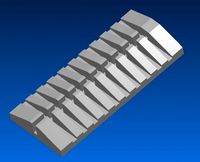
.DESIRED END RESULT
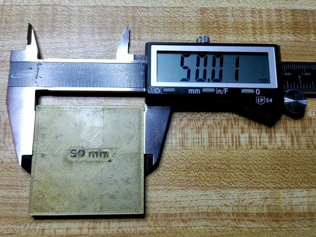
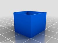
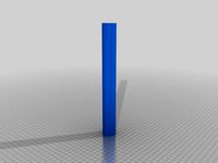
Two printed calibration boxes, one 50mm wide and the other 100mm wide, or as close to those numbers as possible. That will tell you that your printer is ready to produce some nice, dimensionally accurate prints.
.EXTRA TOOLS NEEDED
Outside Micrometer - this one works very well: http://www.amazon.com/gp/product/B004CZ4QB8?psc=1&redirect=true&ref_=oh_aui_search_detailpage
Digital Calipers - this one works very well (best in its price range according to the reviews): http://www.amazon.com/gp/product/B001AQEZ2W?psc=1&redirect=true&ref_=oh_aui_search_detailpage
.STEP 0: Carefully Measure the Filament Diameter
Use natural (uncolored) filament if you can. Surface quality tends to be highest. Colorants - especially ones that make the filament translucent - behave like contaminants, reducing the surface quality. Black filament is notorious for being stuffed with low-quality fillers, so avoid that if you can. Do NOT use specialty filaments such as carbon fiber, wood, metal fill, etc.
Use the Outside Micrometer, not the calipers, to measure your filament in ten places, each at least a foot apart. Enter the measurements into a spreadsheet, and then take the average. Put that into your slicer for the filament diameter.
The filament will want to curl because it cooled on a spool. If you pass the filament between the micrometer's jaws at an angle that directs the curvature towards either jaw, it may throw off the measurement, causing the filament to read thicker than it really is. Instead, hold the filament so that the curvature is at a 90 degree angle relative to the jaws.
.STEP 1: Extrusion Multiplier
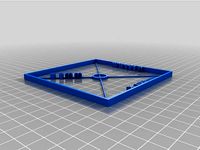
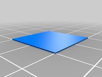
Slice Step 1 - Single-Wall Box.stl with the following settings:
Layer height: 0.1 - 0.2mm is fine, the shorter the better. Taller layers will be sloppier.
Extrusion width: Your nozzle width plus a little extra (e.g., 0.4mm nozzle -> 0.45mm extrusion width)
Extrusion multiplier: Start with a value between 0.9 and 1.0.
Loops: 1
Skin thickness: 0
Infill: None
Speed: 20mm/sec outer loop, 30-40 for everything else (this is not the time to be a speed demon)
Your slicer (I recommend KISSlicer) should produce a square, only one loop thick. It should have no top or bottom surface, and there should be no infill. Print this.
After CAREFULLY separating the square from the print surface, use the Outside Micrometer to measure the thickness of the top few loops. If you measure the first few bottom layers, it'll probably make the reading artificially high, because the first few layers are usually a little bit squished. Focusing on the top few loops is better.
Avoid the corners! The plastic is likely to be a little bit thicker there. I usually measure 1/3 of the way between the two corners, and then 2/3 of the way. That should give you eight measurements for the single-wall box, which you can then average. You should expect the numbers to be a little different in each place. Multi-out hot ends (E3D Chimera and Kraken) may distort the filament more than single-out hot ends (E3D Cyclops and v6, Diamond, Prometheus, regular J-head, etc) because every nozzle is offset from the center of the hot end. That offset can throw the calibration off a little bit.
We're using the Outside Micrometer for this step because its ratcheting mechanism ensures that you're always putting exactly the same amount of force (which is very light) on the filament. Using the regular calipers is less precise.
Measure the box in at least two spots on each side. Some will read higher, others lower. Avoid measuring close to the corners, where the filament will be slightly thicker. You want the average of all the points you measure to be the extrusion width you specified. If it's too thick, reduce the extrusion multiplier. You shouldn't need to go below 0.9. If it's too thin, increase the extrusion multiplier. I usually wind up with values around 0.9 to 0.93 with PLA, PETG and ABS. Two or three iterations of this print should get you dialed in.
Once this step is complete, you're done with the Outside Micrometer and can set it aside.
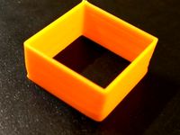
.STEP 2: Small Box
Slice Step 2 - 50mm Box.stl with the following settings:
Loops: 3
Skin thickness: 0.6 or more (not a big deal)
Infill: 15-20% is fine (not a big deal)
Speed: 20-30mm/sec outer loop, 30-50 for everything else
Use the Digital Calipers to measure the width of the 50mm box in several locations. Measure the box across the east-west and north-south directions. (We don't care how tall it is right now.) As stated above, avoid measuring right next to the corners, as well as the bottom 1mm or so, where the plastic may be a little thicker. You should get a number close to 50mm.
.STEP 3: Big Box
Slice Step3-_100mm_Box.stl with the same settings as above.
Print the box and measure it in several places, avoiding the corners and bottom layers. It should come out to about 100mm.
.STEP 4: Figure out where the scaling error is
Now, we'll figure out whether both boxes' scaling errors are about the same, or whether the scaling error is greater for the 100mm box than it is for the 50mm one.
IMPORTANT: NEVER adjust the arm length and extrusion multiplier at the same time! Do only one at a time. If you try to do them both simultaneously, you won't know what is helping and what isn't. Engineers prefer to change as FEW variables as possible at once!
Scaling error = average measured width / what the width should be.
Scaling error same with both pieces: Arm length needs to be adjusted.
Scaling error changes between both pieces: Extrusion multiplier needs to be adjusted.
Example of the arm length needing to be adjusted:
50mm box: 49.9mm wide. 49.9/50 = 0.998.
100mm box: 99.8mm wide. 99.8/100 = 0.998.
In this case, the scaling error is identical. In other words, the scaling error changes proportionally with the size, and we see twice as much at 100mm as we do at 50mm. That's because the printer thinks the arms are longer than they really are, and it isn't pushing them far enough. (Conversely, if the boxes averaged 50.1 and 100.2mm, it would be because the printer thinks the arms are shorter than they really are, and is pushing them too far.) Jump to 5A.
Example of the extrusion multiplier needing to be adjusted:
50mm box: 49.9mm wide. 49.9/50 = 0.998.
100mm box: 99.9mm wide. 99.9/100 = 0.999.
In this case, the scaling error is different on the 100mm box than it is on the 50mm box. They are both too small by 0.1mm, suggesting that the arms are fine, but that the extrusion multiplier is too low. Jump to 5B.
.STEP 5A: Adjusting the Arm Length
New arm length multiplier = average measured width / what the width should be
New arm length = Old arm length * New arm length multiplier
Example:
Arm length = 300 (plug in your own arm length, whatever it is)
49.9/50 = 0.998
New length = 300 * 0.998 = 299.4
After adjusting the arm length, you will need to re-calibrate the printer geometry, as by running GeneB's 3-point calibration, or using the auto-calibration feature in your firmware (assuming it has one).
.STEP 5B: Adjusting the Extrusion Multiplier
If the boxes were too narrow, increase the extrusion multiplier by 0.005 to 0.01. If they were too wide, decrease the extrusion multiplier by 0.005 to 0.01.
Since the printer geometry settings haven't been touched, it's not necessary to re-calibrate the printer. You're only changing the extrusion multiplier in the slicer.
.STEP 6
Re-do Step 2 (print the 50mm box). Check it in several places with your calipers. If your calibration piece doesn't come out close enough to perfect, you can re-start the process.
IMPORTANT: If you adjusted the extrusion multiplier, you will need to re-slice both boxes in Steps 2 and 3. However, if you leave that alone and only adjust the arm length, you don't have to re-slice them.
.EVERY TIME YOU CHANGE FILAMENT
It's very important to re-calculate the filament diameter, and then to re-do Step 1, every time you start using a new spool. Even if it's the same exact color from the same exact manufacturer, chances are good that the diameter will be a little different.
.
Please leave a comment to let me know whether or not this calibration system works for you, and whether you have any comments about how to make it better!
The point of these objects is to help you to fine-tune the calibration on your delta printer to produce dimensionally-accurate parts. (Your printer is probably already close - this will help you get it all the way there.) Before doing this, you'll need to have your printer calibrated with, at a minimum, the GeneB 3-point method described in the Rostock MAX assembly manual. Any version will do. You should also have your extruder steps/mm calibrated - an imperfect process, but this process will compensate for any error in steps/mm.
Dimensional accuracy is marginally important when printing statues and other knick-knacks, but if you want to print something that has to fit with something else, dimensional accuracy matters. It can also help if you have problems with larger prints failing after they've been running for awhile, particularly if they're failing because the hot end is knocking them around (scaling is too small), or you're getting delamination (scaling is too large). If you want to print parts that will be used to form the structural components of a 3D printer or some other machine, this is VERY, VERY important!
.HOW IT WORKS
On a delta robot, the scaling is directly influenced by the arm length setting in the firmware. If your parts are coming out too small, you need to tell the firmware that the arms are slightly shorter, so that it'll know that it has to push them a little bit farther to get the correct result. Likewise, if your parts are coming out too large, you need to tell the firmware that the arms are slightly longer, so that it'll know not to push them quite as far.
You also have to calibrate the filament extrusion multiplier. If it's off, the part will be slightly "fatter" or "thinner" than it's supposed to be. That will be the first step we do.
.AUTO-CALIBRATION FIRMWARE
If your printer has auto-calibration firmware that can adjust the delta geometry variables - delta radius, tower radius and angle, etc. - it may have a feature that allows you to adjust the arm length automatically. At this time, I recommend against letting the firmware adjust the arm length. Let it adjust everything else, but not that.
If you have a Smoothieboard or compatible controller, you can use my auto-calibration Smoothie fork: http://forum.seemecnc.com/viewtopic.php?f=82&t=7640
Duet users can use dc42's fork of RepRapFirmware: https://github.com/dc42/RepRapFirmware
Repetier and Marlin have their own automatic calibration systems, but I haven't had good luck with either of them. I don't recommend anyone in the market to buy a new controller get anything Arduino-based, as they are not future-proof, and struggle just to keep up with the calculations required by a delta robot.
Please note that using the "bed leveling" feature of firmware usually means that it's doing a height adjustment based on probing the bed. That's not the same as calibrating the printer, and is not particularly useful for anything we do here. You can leave it turned on if you need it, but when the instructions say to re-calibrate your printer, that doesn't refer to automatic bed leveling by itself.
.DESIRED END RESULT
Two printed calibration boxes, one 50mm wide and the other 100mm wide, or as close to those numbers as possible. That will tell you that your printer is ready to produce some nice, dimensionally accurate prints.
.EXTRA TOOLS NEEDED
Outside Micrometer - this one works very well: http://www.amazon.com/gp/product/B004CZ4QB8?psc=1&redirect=true&ref_=oh_aui_search_detailpage
Digital Calipers - this one works very well (best in its price range according to the reviews): http://www.amazon.com/gp/product/B001AQEZ2W?psc=1&redirect=true&ref_=oh_aui_search_detailpage
.STEP 0: Carefully Measure the Filament Diameter
Use natural (uncolored) filament if you can. Surface quality tends to be highest. Colorants - especially ones that make the filament translucent - behave like contaminants, reducing the surface quality. Black filament is notorious for being stuffed with low-quality fillers, so avoid that if you can. Do NOT use specialty filaments such as carbon fiber, wood, metal fill, etc.
Use the Outside Micrometer, not the calipers, to measure your filament in ten places, each at least a foot apart. Enter the measurements into a spreadsheet, and then take the average. Put that into your slicer for the filament diameter.
The filament will want to curl because it cooled on a spool. If you pass the filament between the micrometer's jaws at an angle that directs the curvature towards either jaw, it may throw off the measurement, causing the filament to read thicker than it really is. Instead, hold the filament so that the curvature is at a 90 degree angle relative to the jaws.
.STEP 1: Extrusion Multiplier
Slice Step 1 - Single-Wall Box.stl with the following settings:
Layer height: 0.1 - 0.2mm is fine, the shorter the better. Taller layers will be sloppier.
Extrusion width: Your nozzle width plus a little extra (e.g., 0.4mm nozzle -> 0.45mm extrusion width)
Extrusion multiplier: Start with a value between 0.9 and 1.0.
Loops: 1
Skin thickness: 0
Infill: None
Speed: 20mm/sec outer loop, 30-40 for everything else (this is not the time to be a speed demon)
Your slicer (I recommend KISSlicer) should produce a square, only one loop thick. It should have no top or bottom surface, and there should be no infill. Print this.
After CAREFULLY separating the square from the print surface, use the Outside Micrometer to measure the thickness of the top few loops. If you measure the first few bottom layers, it'll probably make the reading artificially high, because the first few layers are usually a little bit squished. Focusing on the top few loops is better.
Avoid the corners! The plastic is likely to be a little bit thicker there. I usually measure 1/3 of the way between the two corners, and then 2/3 of the way. That should give you eight measurements for the single-wall box, which you can then average. You should expect the numbers to be a little different in each place. Multi-out hot ends (E3D Chimera and Kraken) may distort the filament more than single-out hot ends (E3D Cyclops and v6, Diamond, Prometheus, regular J-head, etc) because every nozzle is offset from the center of the hot end. That offset can throw the calibration off a little bit.
We're using the Outside Micrometer for this step because its ratcheting mechanism ensures that you're always putting exactly the same amount of force (which is very light) on the filament. Using the regular calipers is less precise.
Measure the box in at least two spots on each side. Some will read higher, others lower. Avoid measuring close to the corners, where the filament will be slightly thicker. You want the average of all the points you measure to be the extrusion width you specified. If it's too thick, reduce the extrusion multiplier. You shouldn't need to go below 0.9. If it's too thin, increase the extrusion multiplier. I usually wind up with values around 0.9 to 0.93 with PLA, PETG and ABS. Two or three iterations of this print should get you dialed in.
Once this step is complete, you're done with the Outside Micrometer and can set it aside.
.STEP 2: Small Box
Slice Step 2 - 50mm Box.stl with the following settings:
Loops: 3
Skin thickness: 0.6 or more (not a big deal)
Infill: 15-20% is fine (not a big deal)
Speed: 20-30mm/sec outer loop, 30-50 for everything else
Use the Digital Calipers to measure the width of the 50mm box in several locations. Measure the box across the east-west and north-south directions. (We don't care how tall it is right now.) As stated above, avoid measuring right next to the corners, as well as the bottom 1mm or so, where the plastic may be a little thicker. You should get a number close to 50mm.
.STEP 3: Big Box
Slice Step3-_100mm_Box.stl with the same settings as above.
Print the box and measure it in several places, avoiding the corners and bottom layers. It should come out to about 100mm.
.STEP 4: Figure out where the scaling error is
Now, we'll figure out whether both boxes' scaling errors are about the same, or whether the scaling error is greater for the 100mm box than it is for the 50mm one.
IMPORTANT: NEVER adjust the arm length and extrusion multiplier at the same time! Do only one at a time. If you try to do them both simultaneously, you won't know what is helping and what isn't. Engineers prefer to change as FEW variables as possible at once!
Scaling error = average measured width / what the width should be.
Scaling error same with both pieces: Arm length needs to be adjusted.
Scaling error changes between both pieces: Extrusion multiplier needs to be adjusted.
Example of the arm length needing to be adjusted:
50mm box: 49.9mm wide. 49.9/50 = 0.998.
100mm box: 99.8mm wide. 99.8/100 = 0.998.
In this case, the scaling error is identical. In other words, the scaling error changes proportionally with the size, and we see twice as much at 100mm as we do at 50mm. That's because the printer thinks the arms are longer than they really are, and it isn't pushing them far enough. (Conversely, if the boxes averaged 50.1 and 100.2mm, it would be because the printer thinks the arms are shorter than they really are, and is pushing them too far.) Jump to 5A.
Example of the extrusion multiplier needing to be adjusted:
50mm box: 49.9mm wide. 49.9/50 = 0.998.
100mm box: 99.9mm wide. 99.9/100 = 0.999.
In this case, the scaling error is different on the 100mm box than it is on the 50mm box. They are both too small by 0.1mm, suggesting that the arms are fine, but that the extrusion multiplier is too low. Jump to 5B.
.STEP 5A: Adjusting the Arm Length
New arm length multiplier = average measured width / what the width should be
New arm length = Old arm length * New arm length multiplier
Example:
Arm length = 300 (plug in your own arm length, whatever it is)
49.9/50 = 0.998
New length = 300 * 0.998 = 299.4
After adjusting the arm length, you will need to re-calibrate the printer geometry, as by running GeneB's 3-point calibration, or using the auto-calibration feature in your firmware (assuming it has one).
.STEP 5B: Adjusting the Extrusion Multiplier
If the boxes were too narrow, increase the extrusion multiplier by 0.005 to 0.01. If they were too wide, decrease the extrusion multiplier by 0.005 to 0.01.
Since the printer geometry settings haven't been touched, it's not necessary to re-calibrate the printer. You're only changing the extrusion multiplier in the slicer.
.STEP 6
Re-do Step 2 (print the 50mm box). Check it in several places with your calipers. If your calibration piece doesn't come out close enough to perfect, you can re-start the process.
IMPORTANT: If you adjusted the extrusion multiplier, you will need to re-slice both boxes in Steps 2 and 3. However, if you leave that alone and only adjust the arm length, you don't have to re-slice them.
.EVERY TIME YOU CHANGE FILAMENT
It's very important to re-calculate the filament diameter, and then to re-do Step 1, every time you start using a new spool. Even if it's the same exact color from the same exact manufacturer, chances are good that the diameter will be a little different.
.
Please leave a comment to let me know whether or not this calibration system works for you, and whether you have any comments about how to make it better!
Similar models
thingiverse
free
(yet another) Printer measure calibration object by tdpt
...height.
simply print it with your desired settings, measure the printed object, and scale accordingly (example coming eventually)
thingiverse
free
100mm square and 50mm circle calibration (XY calibration) by SammyLinden
...be 141.42mm from opposite corners, if it is straight.
model is 2mm thick, but you can print only one layer to measure your print.
thingiverse
free
CoreXY Calibration
...me is square, the bed is leveled, and the z-offset calibrated.
these first steps are important to guarantee accurate calibration.
thingiverse
free
Simple Calibration & Centring Print by SmithRC
...steps needed in your firmware to make the dimensions correct.
re-print and re test a few times and average the results if needed.
thingiverse
free
Single width walls for perimeter calibration by pbelt
...adjust this. extrusion multiplier = expected value / measured value. in any case it shouldn't be outside the range 0.9 - 1.1.
thingiverse
free
Advanced Delta Printer Calibration (tower position + individual diagonal rod) by dolpin
...on and calibrate your printer in the marlin firmware.
check the instructions for the calibration steps and how to correct this.
thingiverse
free
20x10x15mm Dimensional Calibration Test Plug Set by macelius
...f the peg in the hole with some gap left (if it's not stuck there already) and lever with a screwdriver or twist with pliers.
thingiverse
free
Extrusion multiplier calibration by 3D_MaxMaker
...
give it a try!! leave your comments. what method you use to calibrate your printer? show us your improvements, before and after.
thingiverse
free
Prusa i3 MK2(S)/MK2.5/MK3 Live Z Calibration Steps by Bolerro
...eps.
each corner should measure out to 0.200 when you are done.
congratulations! your printer should be purring like a kitten now
thingiverse
free
Calibration box to fine tune Default Extrusion Width, X/Y/Z/E Steps, and Flow Rate by tonyyoungblood
...e versa.
note, the objects have changed slightly since the pictures were taken. the picture with the measurements is accurate.
626Pilot
thingiverse
free
Planetary EZStruder Mount (geared stepper to EZStruder) by 626Pilot
...e the right screws to use with his, it's basically the same thing, so pick whichever one matches the screws you have on hand.
thingiverse
free
Rostock MAX 250mm Calibration Cylinder by 626Pilot
...bad delta rod length or printer radius setting in configuration.h) will have done so by 25cm in my experience.
slice as a vase.
thingiverse
free
Big & Tall Filament Holder Arm for Rostock MAX by 626Pilot
....update - 7-2-2014: rounded out the top edge of the arm, where it carries the spool. there should be less friction and noise now.
thingiverse
free
E3D Chimera/Cyclops mount for Rostock MAX by 626Pilot
...able management (removed one wire clip and took the tang out of the other), and added some stiffening strakes to the top surface.
thingiverse
free
Cable Clip for Trick Laser Rostock MAX METAL by 626Pilot
...e using unbrako #10-32 x 1/2 low-head caphead screws and 80/20 inc t-slot hw 10 series 10-32 roll-in t-nut w/ball spring #3922 n.
thingiverse
free
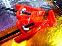
Rostock MAX Tower Alignment Clamps by 626Pilot
...jects are a higher priority for me right now, but if some people ask i'll set aside some time to finish the permanent clamps.
thingiverse
free
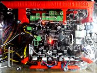
Smoothieboard 3/4/5X Mount for Rostock MAX by 626Pilot
...tabilize it while you do this. otherwise, you may shear off the top standoffs!
inspired by mhackney/eclecticangler's mount.
thingiverse
free
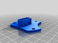
Endstop Z-Probe Mount for Rostock MAX/Orion/MAX Metal by 626Pilot
...itch to ensure that it always contacts the print surface when the end of the arm is lined up with those marks. this is important!
thingiverse
free

Ruby HallO Bed Leveling Probe by TheUnderDog
...ultimaker 2 on a smothieware board. i couldn't use 626pilot#39;s fork of the smoothieware firmaware, but still i used...
thingiverse
free
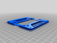
Azteeg X5 Mini Mount for Rostock MAX by 626Pilot
...#39;t have an account there, what the heck are you waiting for? it's hands down the best place to go for rostock max support.
Dimensional
turbosquid
$5

Dimensional Gateway
... available on turbo squid, the world's leading provider of digital 3d models for visualization, films, television, and games.
3ddd
$1
3-Dimensional Purple
...3-dimensional purple
3ddd
1326 - 889. пригодится для перин и одеял.
3d_export
$20
4 Dimensional Cube 3D Model
...4 dimensional cube 3d model
3dexport
4d cube
4 dimensional cube 3d model shaputer 7644 3dexport
3d_export
$8

SNK CONTROLLER TEAM DIMENSIONAL 3D 3D Model
...controller team dimensional 3d equipo maniobras armas cuerpo
snk controller team dimensional 3d 3d model lococr98 86977 3dexport
3d_export
$180
automated three-dimensional garage
...the purchase.<br>designed with solidworks 2017;vray with keyshot<br>-------------------------------------------------
cg_studio
$59
three-dimensional console, concept device3d model
... .obj .max - three-dimensional console, concept device 3d model, royalty free license available, instant download after purchase.
3d_export
$20

three-dimensional modeling and rendering of shaver
...low, the material texture maps are correctly aligned and set up correctly - the texture format is jpg/png/exr /hdr - four cameras
3d_export
$8
coats and skirt 3d
...coats and skirt 3d 3dexport three-dimensional design of clothes with software marvelous and...
3d_export
$6
3d clothing
...3d clothing 3dexport three-dimensional design of clothes with software: marvelous and clo3d and...
3d_export
$12
automatic pipe cutting machine
...aspects and high efficiency. the drawings contain three-dimensional and two-dimensional engineering drawings, and a list of...
Accuracy
turbosquid
$15
Accuracy International Weapon
...ee 3d model accuracy international weapon for download as obj on turbosquid: 3d models for games, architecture, videos. (1217320)
turbosquid
$5
Accuracy International AWM
... available on turbo squid, the world's leading provider of digital 3d models for visualization, films, television, and games.
3ddd
free
Accuracy International L96A1 / Arctic Warfare
...роизводства: середина 1980-х. масса, кг: 6,8 (без оптического прицела) длина, мм: 1124—1194. длина ствола, мм:. 22" (655 мм)
humster3d
$75
3D model of Accuracy International AS50
... 3d model of accuracy international as50 in various file formats. all our 3d models were created maximally close to the original.
3d_export
$99

Accuracy International Arctic Warfare L96A1 3D Model
...ctic warfare british weapon gun l96a1 rifle sniper
accuracy international arctic warfare l96a1 3d model humster3d 101360 3dexport
turbosquid
$10
Kitchen Set - High Accuracy 3D model
...set - high accuracy 3d model for download as ma, fbx, and obj on turbosquid: 3d models for games, architecture, videos. (1537682)
turbosquid
$1

Accuracy International AWM sniper rifle with scope
...m sniper rifle with scope for download as obj, fbx, and blend on turbosquid: 3d models for games, architecture, videos. (1386281)
humster3d
$75
3D model of Accuracy International Arctic Warfare (L96A1)
...acy international arctic warfare (l96a1) in various file formats. all our 3d models were created maximally close to the original.
cg_studio
$99
Accuracy International Arctic Warfare (L96A1)3d model
...d .3ds - accuracy international arctic warfare (l96a1) 3d model, royalty free license available, instant download after purchase.
3d_export
$5

apple emblem
...emblem 3dexport the apple logo in 3d model, high accuracy & nice curves, the only model in the world...
Calibration
turbosquid
$15
DEFIBRILLATOR CALIBRATORS
... available on turbo squid, the world's leading provider of digital 3d models for visualization, films, television, and games.
turbosquid
$3
Calibration Test Benches
...libration test benches for download as 3ds, obj, c4d, and fbx on turbosquid: 3d models for games, architecture, videos. (1355804)
turbosquid
$79
Tag Heuer Monaco Calibre 11
...free 3d model tag heuer monaco calibre 11 for download as max on turbosquid: 3d models for games, architecture, videos. (1634427)
turbosquid
$50
Smith & Wesson 50 Calibre Magnum
... available on turbo squid, the world's leading provider of digital 3d models for visualization, films, television, and games.
3d_export
$10
Laboratory Calibration Weight Set 1 3D Model
... 3d model
3dexport
laboratory lab science equipment weight set
laboratory calibration weight set 1 3d model bessoo 88084 3dexport
3d_export
$15
Laboratory Scale and Calibration Weight Set 3D Model
...port
laboratory lab science equipment weight set scale
laboratory scale and calibration weight set 3d model bessoo 88203 3dexport
3d_export
$5
3D printer filament calibration tool 3D Model
...ernier
3d printer filament calibration tool 3d model download .c4d .max .obj .fbx .ma .lwo .3ds .3dm .stl locoman 107942 3dexport
3d_export
$59
tag heuer link calibre 16 watch
...built to real-world scale. units used: centimeters. model is 18 centimeters tall.<br>scene objects are organized by groups.
3d_export
free
laser height reference calibration tool opt lasers
...ind out more about the engraving and cutting laser heads, this item was designed to work with, take a look at the following page:
3d_export
$99
Patek Philippe White Gold Calibre 89
...br>please note: this 3d model like all my other models cannot be used as nft, as is or modified<br>thank you for reading
Delta
design_connected
$16

Delta
...delta
designconnected
lj lamps delta computer generated 3d model. designed by janowski-lenhart, sasha.
design_connected
$16
Delta
...delta
designconnected
arflex international spa delta computer generated 3d model. designed by koivisto, eero.
design_connected
$13
Delta
...delta
designconnected
emu group delta armchairs computer generated 3d model. designed by marin chiaramonte .
3ddd
$1
Delta Light
...delta light
3ddd
delta light , you-turn reo 3033
точечний светильник delta light
3ddd
$1
Blanco / delta
...blanco / delta
3ddd
blanco , мойка
мойка blanco delta со смесителем
3ddd
$1
Delta Light Spot
...delta light spot
3ddd
delta light
светильник фирмы delta light
3ddd
free
Bianchi Delta LVMDLT200100
...i delta lvmdlt200100
3ddd
bianchi delta , смеситель
смеситель bianchi delta lvmdlt200100
design_connected
free
Delta 190
...delta 190
designconnected
free 3d model of delta 190 by zanotta designed by progetti, emaf.
design_connected
$27
Delta 211
...delta 211
designconnected
zanotta delta 211 computer generated 3d model. designed by progetti, emaf.
design_connected
$27
Delta 234
...delta 234
designconnected
zanotta delta 234 computer generated 3d model. designed by progetti, emaf.
Printers
archibase_planet
free
Printer
...inter
archibase planet
printer laser printer pc equipment
printer n120614 - 3d model (*.gsm+*.3ds) for interior 3d visualization.
archibase_planet
free
Printer
...rchibase planet
laser printer office equipment computer equipment
printer - 3d model (*.gsm+*.3ds) for interior 3d visualization.
turbosquid
$100
Printer
...er
turbosquid
royalty free 3d model printer for download as on turbosquid: 3d models for games, architecture, videos. (1487819)
turbosquid
$3
Printer
...turbosquid
royalty free 3d model printer for download as max on turbosquid: 3d models for games, architecture, videos. (1670230)
turbosquid
$1
printer
...turbosquid
royalty free 3d model printer for download as max on turbosquid: 3d models for games, architecture, videos. (1595546)
turbosquid
$1
printer
...turbosquid
royalty free 3d model printer for download as max on turbosquid: 3d models for games, architecture, videos. (1595105)
turbosquid
$10
Printer
...id
royalty free 3d model printer for download as max and 3dm on turbosquid: 3d models for games, architecture, videos. (1607146)
turbosquid
$7
Printer
...royalty free 3d model printer for download as ma, ma, and obj on turbosquid: 3d models for games, architecture, videos. (1644580)
turbosquid
$30
Printer
... available on turbo squid, the world's leading provider of digital 3d models for visualization, films, television, and games.
turbosquid
$20
Printer
... available on turbo squid, the world's leading provider of digital 3d models for visualization, films, television, and games.