GrabCAD
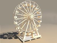
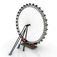
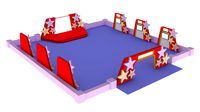
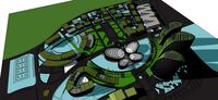
DESKTOP LAYOUT OF THE FERRIS WHEEL ATTRACTION DRIVE
by GrabCAD
Last crawled date: 1 year, 11 months ago
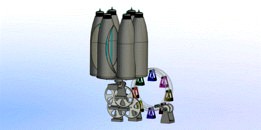
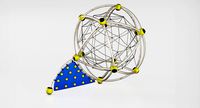
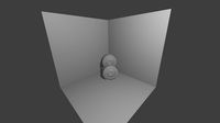
The desktop layout of the Ferris wheel drive during operation demonstrates the circular translational movement of the booths. The layout consists of two cylindrical straight-toothed involute gears made in the form of rings with the numbers of teeth 18, 90 and a module of 2 mm, which are connected to each other by M4 bolted joints with a bolt length of 40 mm in the amount of 8 pieces. Flange-type bolted joints connect the annular gears into a block of gears of the same size in such a way that there is a space between them in which the Ferris wheel booths fixed with bolts are placed. The gear unit is supported by four gears with the number of teeth equal to 18, each of which is cantilevered mounted on a pivotally fixed support. The shaft of one of the gears is also connected to the handle, through which the Ferris wheel can be driven manually – by rotating the handle.
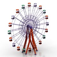
The second variant of the Ferris wheel layout drive is a wind wheel with six blades and a vertical axis of rotation. The blades are made in the form of a plastic bottle, in the body of which there is a cutout measuring from 30 to 50 percent of the side surface. Each of the bottles contains a cork. There is one through central axial hole in the cork and at the bottom of the bottle. With the help of rods, at the ends of which there is an M6 thread and which exceed the height of the bottle by their length, threaded connections through the cork and the bottom of the bottle, the blades are fixed to the disc base of the wind wheel. On the opposite side of the blades on the disk base there is a toothed crown of a conical wheel. In the presence of wind at a speed of 1-2 m/s, the mechanical energy of the rotating wind wheel is transmitted through an orthogonal conical straight-toothed involute gear drive from wheels with tooth numbers 18, 18 and a module equal to 2 mm to a four-stage gear cylindrical gearbox consisting of wheels with tooth numbers 18, 90 with a module of 1 mm. The output shaft of the gearbox is rigidly connected to one of the supporting gears of the Ferris wheel.
The estimated time of one revolution of the Ferris wheel is 17.4 minutes at a wind wheel rotation speed of 180 rpm. The power of at least 1 watt is sufficient to drive the wind wheel. When modeling the movement of the layout by means of the T-Flex Dynamics engineering analysis module, an amendment was added to the standard values of the friction coefficients in the form of a coefficient of 0.25 – to ensure a smoother rotation of the Ferris wheel booths during its rotation. The minimum wind speed of 1.55 m/s was taken as the circumferential speed of the wind wheel, which, through the connection of linear and angular velocities, made it possible to determine the radius of the location of the blades of the wind wheel.
Similar models
grabcad
free

Involute Gear Mechanism
...e profiles of the teeth are involutes of a circle. the involute profile gear tooth produces a constant ratio of rotational speed.
grabcad
free

Involute gear editor
...- addendum modification coefficient pinion / gear
should be updated after each change!!!!!
especially:
waterjet cutter
wire edm
grabcad
free

gear whell spur toothed
... that will be generated with 2 parameters. tooth modulus and number of teeth. it is a real involute gear with a calculated width.
3d_export
$5
gear wheel 15 teeth 15cm diameter modul 1cm
...xtremely precisely machined tooth base. 15 teeth 15cm diameter 1cm thick modul 1cm compartiebel with all my gears with modul 1cm!
3d_export
$5
gear wheel 10 teeth 10cm diameter modul 1cm
...tremely precisely machined tooth base. 10 teeth 10cm diameter 1cm thick modulo 1cm compartiebel with all my gears with modul 1cm!
grabcad
free

Single-stage reducer conical
...the diameter of the outlet end of the driven shaft dvih = 85 mm
/------------------------------------------------- -------------/
thingiverse
free

16 Tooth, 8 Tooth Compound Gear by HandCrank
...th compound gear by handcrank
thingiverse
this is a small 16 and 18 tooth compound gear. it has the involute gear tooth profile.
cg_trader
$5
Gear wheel 15 teeth 15cm diameter modul 1cm
... modul 1cm compartiebel with all my gears with modul 1cm! gear mechanics technic element industry industrial part industrial part
cg_trader
$5

Gear wheel 10 teeth 10cm diameter modul 1cm
... modul 1cm
compartiebel with all my gears with modul 1cm! gear mechanics technic element industry industrial part industrial part
grabcad
free

Differential Gearbox
...ounted on the carrier 5 which supports the planetary bevel gears 4 which engage the driven bevel gears 3 attached to the axles 1.
Ferris
3d_ocean
$19
Ferry
...e of motor vehicles, cargo and passengers across the waterway. include standart materials scene and v-ray scene with environment.
turbosquid
$5
FERRY
...y
turbosquid
royalty free 3d model ferry for download as 3dm on turbosquid: 3d models for games, architecture, videos. (1315967)
turbosquid
$5
FERRY
...y
turbosquid
royalty free 3d model ferry for download as 3dm on turbosquid: 3d models for games, architecture, videos. (1315964)
turbosquid
$29
ferry
...ty free 3d model ferry for download as c4d, obj, fbx, and 3ds on turbosquid: 3d models for games, architecture, videos. (1659242)
3d_export
$6
Ferri
...ferri
3dexport
a first phase of a sculpture
turbosquid
free
FERRY
... available on turbo squid, the world's leading provider of digital 3d models for visualization, films, television, and games.
3d_ocean
$25
Ferris Wheel
...ris wheel
3docean
fair ferris fun wheel
high quality ferris wheel. includes the clay material and model. rendered with mental ray
archibase_planet
free
Ferris wheel
...eel
archibase planet
ferris wheel carousel carrousel
ferris wheel n171213 - 3d model (*.gsm+*.3ds) for exterior 3d visualization.
3d_export
$90

ferry
...ferry
3dexport
simple rendering of the scene file
archibase_planet
free
Ferris wheel
...se planet
ferris wheel merry-go-round whirligig
ferris wheel fima n150412 - 3d model (*.gsm+*.3ds) for exterior 3d visualization.
Attraction
turbosquid
$26
Attraction hill A
...
royalty free 3d model attraction hill a for download as fbx on turbosquid: 3d models for games, architecture, videos. (1288465)
turbosquid
$34
Attraction cars
... available on turbo squid, the world's leading provider of digital 3d models for visualization, films, television, and games.
3ddd
$1
Комод Сaracole Opposites Attract
... - con-closto-068
collection: classic contemporary
dimensions: 72w x 23.5d x 38h
ссылка на сайт производителя: www.caracole.com
turbosquid
$20
Childrens Attraction Sphere
...childrens attraction sprehe for download as max, obj, and fbx on turbosquid: 3d models for games, architecture, videos. (1302199)
turbosquid
$25
Roche Bobois Attraction
... available on turbo squid, the world's leading provider of digital 3d models for visualization, films, television, and games.
turbosquid
$10
Attractions Rides for Kids
... available on turbo squid, the world's leading provider of digital 3d models for visualization, films, television, and games.
3d_export
$19
Roche Bobois Attraction 3D Model
...ttraction furniture comfortable beautiful interior 3d model living sitting
roche bobois attraction 3d model anna3d 92607 3dexport
3d_export
$5

attraction rocking hedgehog
... for visualization corona render. the archive contains files: 3ds max 2017, 3ds max 2014, fbx, obj. thank you for choosing us!)))
turbosquid
$20

Perpetuum mobile (Capillary attraction)
... available on turbo squid, the world's leading provider of digital 3d models for visualization, films, television, and games.
3d_export
$18
fountain-attractions-rockery-backyard
...3dexport
fountain-attractions-rockery-backyard<br>max 2015 v-ray 3 max 2015<br>textures<br>all files in zip...
Desktop
3d_export
$5
desktop
...desktop
3dexport
full desktop
3d_export
$15

Desktop
...desktop
3dexport
desktop, monitor, system unit, backlit keyboard.
3d_export
$5

desktop
...desktop
3dexport
desktop with shelving. very convenient and practical find.
turbosquid
$5
Desktop
...turbosquid
royalty free 3d model desktop for download as jpg on turbosquid: 3d models for games, architecture, videos. (1329464)
turbosquid
$1
Desktop
...turbosquid
royalty free 3d model desktop for download as fbx on turbosquid: 3d models for games, architecture, videos. (1661325)
3d_export
$10
110x60 desktop
...110x60 desktop
3dexport
110x60 desktop
turbosquid
$20

Desktop
...lty free 3d model desktop for download as blend, fbx, and obj on turbosquid: 3d models for games, architecture, videos. (1624648)
turbosquid
$20
Desktop
...oyalty free 3d model desktop for download as ma, obj, and fbx on turbosquid: 3d models for games, architecture, videos. (1309418)
turbosquid
$15

Desktop
...yalty free 3d model desktop for download as 3ds, obj, and c4d on turbosquid: 3d models for games, architecture, videos. (1445073)
3d_export
$5
desktop
...desktop
3dexport
a desk will fit into the room
Layout
turbosquid
$30

Layout exhibition
...
royalty free 3d model layout exhibition for download as max on turbosquid: 3d models for games, architecture, videos. (1577107)
turbosquid
$40
food court layout
...
royalty free 3d model food court layout for download as max on turbosquid: 3d models for games, architecture, videos. (1582200)
turbosquid
$20
Layout star decor
...
royalty free 3d model layout star decor for download as max on turbosquid: 3d models for games, architecture, videos. (1576183)
turbosquid
$1

Simple Mug For Layout
... 3d model simple mug for layout for download as fbx and blend on turbosquid: 3d models for games, architecture, videos. (1332065)
turbosquid
$40
Office Layout Design
... available on turbo squid, the world's leading provider of digital 3d models for visualization, films, television, and games.
turbosquid
$15
Cafe design layout
... available on turbo squid, the world's leading provider of digital 3d models for visualization, films, television, and games.
turbosquid
$5

Pyramids of Giza - Layout
... available on turbo squid, the world's leading provider of digital 3d models for visualization, films, television, and games.
turbosquid
$125
BIG VILLA HOME LAYOUT
...yalty free 3d model big villa home layout for download as skp on turbosquid: 3d models for games, architecture, videos. (1259969)
turbosquid
$90
iconic commercial buildings layout
... model iconic commercial buildings layout for download as skp on turbosquid: 3d models for games, architecture, videos. (1260664)
3ddd
$1
LAYOUT ISOLAGIORNO Easy mono sofa
... isolagiorno , easy
upholstered 3 seater sofa
dimensions: 230cm lenght
Drive
turbosquid
$90
Drive
...turbosquid
royalty free 3d model drive for download as blend on turbosquid: 3d models for games, architecture, videos. (1654393)
3d_export
$10

cycloidal drive
...cycloidal drive
3dexport
cycloidal drive
3d_ocean
$5
Flash Drive
...h drive included : – materials – scene ( lighs / room ) – .c4d + .obj for any questions please feel free to contact me thank you.
3d_ocean
$5

Usb drive
...s shaders and a lighting setup. it also has a small animation of it going in and out. i saved it out as both a .blend file and...
3d_ocean
$5

Pen Drive
...est computer drive game model good low poly new pen pen drive textured unwrapped uv very low poly
a very beautiful low poly model
3d_ocean
$10
External hard drive
... is a detailed model of a trekstor external hard drive. you can easily modify the label on the top. simply edit the text objects.
turbosquid
$60

Star Drive
...squid
royalty free 3d model star drive for download as blend on turbosquid: 3d models for games, architecture, videos. (1254314)
turbosquid
$50
Star Drive
...squid
royalty free 3d model star drive for download as blend on turbosquid: 3d models for games, architecture, videos. (1263524)
turbosquid
$45
Star Drive
...squid
royalty free 3d model star drive for download as blend on turbosquid: 3d models for games, architecture, videos. (1287060)
turbosquid
$40
Star Drive
...squid
royalty free 3d model star drive for download as blend on turbosquid: 3d models for games, architecture, videos. (1261902)
Wheel
archibase_planet
free
Wheel
...l steering control steering wheel
wheel ship steering wheel n060215 - 3d model (*.gsm+*.3ds+*.max) for exterior 3d visualization.
3d_ocean
$14
Wheel
...wheel
3docean
car rim car wheel rim wheel
high poly car wheel design. 16,840 polys
3d_export
free
wheel
...wheel
3dexport
wheel
3d_export
free
wheel
...wheel
3dexport
wheel
3d_export
free
Wheel
...wheel
3dexport
wheel
3d_export
$5

wheel
...wheel
3dexport
wheel for car.
3d_export
$5
wheel
...wheel
3dexport
car wheel
3d_export
$5
wheel
...wheel
3dexport
car wheel
3d_export
$5
wheel
...wheel
3dexport
car wheel
3d_export
$5
wheel
...wheel
3dexport
car wheel