Thingiverse
Delta 5 Race Timer Shield Case by techyg
by Thingiverse
Last crawled date: 3 years ago
Background
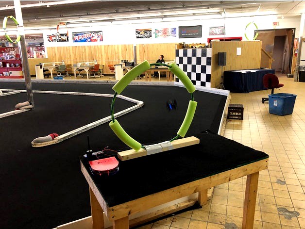
The Delta 5 Race Timer is an innovative, cost effective solution for keeping track of race laps when racing FPV (First Person View). The designer of the Delta 5 Race Timer is Scott Chin. The system is open source, and utilizes the video transmitter frequencies instead of traditional transponders. Video transmitters that work with this system can be purchased for as low as $10 (ex. Eachine VTX03). For more information about Delta 5 Race Timer, visit the following web site:
https://github.com/scottgchin/delta5_race_timer
The Delta 5 Race Timer system has native lap timing software, written in Python. It also integrates with LiveTime Scoring Engine, found here:
https://www.livetimescoring.com/
In the spirit of open source and community, I wanted to post my design. Before using my design, I encourage you to take a look at Scott's Github link above, or join the Facebook group:
https://www.facebook.com/groups/Delta5RaceTimer/
Scott has been working on a PCB that will greatly simplify the project (as of uploading this, it is still a WIP), though it won't fit in the same form factor as what I have here. His solution should save you a significant amount of time and effort, and will generally be more supported as others will be using it.
With that in mind, the design here gives you a lot of flexibility and I think it looks pretty cool!
Before you get started
This system is fantastic, and if you go with an 8 node set up, it should be doable for around $200, and of course less if you already have some of the components. I feel that this system is on par with the $600 Immersion LapRF! However, it is definitely a lot of work putting it together.
I have compared this system with some of the existing solutions (such as individual race trackers- both the Immersion Puck, and the TBS race tracker) on the market, and the timing is on par or better.
What to be aware of...
If you have never used a linux based / command line system before, you may have some challenges with the Raspberry Pi setup. Fortunately, the setup process for getting a raspberry pi up and running is pretty easy. You can also buy an SD Card pre-loaded with the image (though you still have to install the Race Timer software). I recommend joining the Facebook group if you need help.
Basic soldering skills, and soldering equipment are going to be needed. I assume that you're probably already in the RC hobby if you're reading this, so this shouldn't be a problem for most people.
Hardware
First, decide how many nodes you want to set up. One node can monitor one video frequency (in the 5.8 ghz range). The hardware currently supports up to 8 nodes. I started out with 4 and later added more. Please note: the software currently doesn't allow switching, and only monitors one channel per node. This means that the hardware is a bit more costly, but the lap times are going to be very accurate with the highest resolution possible.
All hardware required is listed on the Github link above, but I'll summarize it here and also add a few additional parts that I used. I purchased almost all of mine from Banggood. Prices listed are from there as of the time of writing this.
Each node requires an Arduino Nano. $8 each.
Each node also requires an RX5808. This is the video receiver. $10 each.
A Raspberry Pi 3 Model B - Pi 2's will NOT work (I believe due to timing/I2C communication). $35
1K resistors: Quantity 3. 100K resistor: Quantity 1. This is per each node. (Total of 24 1K resistors, 8 100K resistors if building 8 nodes). I recommend purchasing a resistor kit on eBay, or going straight to mouser.com and buying them individually. Cost: Around $10-$15
You will need one 5v 2.5A voltage regulator. This will be sufficient for powering all 8 nodes, which should draw around 2A of current (including the Rasp Pi). I recommend this one: https://www.pololu.com/product/2850 Cost: $12
I used a 4x6cm protoboard. This is required in order to fit in my case. Only $7 for a 24 pack. I used these:https://www.amazon.com/Uxcell-a14041800ux1143-Double-Protoboard-Prototyping/dp/B0166GCD42/
On Scott's PCB, he also sources the Arduino Nano's using a 3.3v regulator. This helps keep the heat of the RX5808's down. I don't use a 3.3v regulator but instead blow a fan on my electronics.
Other stuff:
You will need an SD card for the Rasp Pi. I recommend a 16GB one.
I used a 5000mah 3S battery to power my setup (via the 5v regulator). It lasts several hours, depending on how many nodes you have hooked up. $25
You will need to decide how you want to connect to it. Many people just use a really long ethernet cable (eg. 50-100ft). Wifi is also an option. Some people incorporate a small "travel hotspot" into their setup ($15-20). The raspberry Pi is capable of being it's own hotspot, but I wouldn't recommend it because the wifi range on the Pi is not very good.
Specific stuff for the case design:
I purchased this 80mm fan from Amazon. It works great with the design: https://www.amazon.com/MASSCOOL-80mm-Blue-Cooling-BLD-08025S1M/dp/B000S396YU
For the arduino nodes, you will need M2 screws, 6mm long. I use 3 per node (although there are holes for 4).
You will need M3 (quantity 4) screws for the case. I use longer screws on the bottom (15mm should work) and shorter screws on the top (10mm). The lengths aren't really important on these.
You will also need 2 36mm Power Distribution Boards. This helps make the wiring easier. I also used two short M3 screws and some lock nuts to hold in place. You could also glue them down if you wanted to.
You may want to use JST cables (as pictured) to allow for easy connect/disconnect. Same thing for the I2C connections- except perhaps Servo cables would be better. In my design, I used JST cables for the power, but just ran longer wire and directly soldered the I2C cables.
I used PETG filament. It's very sturdy and should survive drops.
You will need some hookup wire. I use 24 AWG gauge wire from Striveday on Amazon: https://www.amazon.com/StrivedayTM-Electric-electronic-Industries-electrics/dp/B01KQ0D3M0/
About the design
The case allows for up to 8 nodes. 4 are mounted on the bottom, and 4 on the top.
The 80mm fan cut out allows for rapid cooling.
I tried to get this case to be very compact, so there isn't a ton of room inside it.
About the wiring
I soldered the Arduino Nano straight to the protoboard.
Feel free to use my wiring layout/design. Use the comments if you have any questions.
On later nodes, I moved the Nano over one row to the left, because the first version blocked the bottom right screw hole.
I sourced the 5v power directly to the Nano via the 5v/GND pins. Please double check that you have the right pins before providing power, as there is no reverse current protection when powering with the pins. The RX5808's are also powered from these same pins. (Side note: the Nano is capable of powering up to 500ma over the 5V/GND pins, but the GPIO pins are designed for 50ma only).
Summary
The design is still a bit of a work in process, and I'll be updating it. I am currently on revision 3- you'll notice that some of the pictures have different color PETG, and those were some earlier prototype designs. If you have any comments/recommendations for improvements, please feel free to mention those in the comments.
Similar models
thingiverse
free

Race timer case by BMLfpv
...e a credit to techy g, i have used his text as a basis and also recommend to take a look at his version of the delta5 race timer.
thingiverse
free

Rotorhazard Drone Racing Personal Lap timer - One Node by Cerberus
...screw (lid mounting) 1 x 5v regulator (pololu or similar ...
thingiverse
free

Underbed Motion Activated Light by TexWorkshop
...
protoboard
l7805 voltage regulator (to power arduino)
the code and schematics is in "thing" files .
and that's it!
thingiverse
free

Delta 5 Lap Timer/Race Timer (D5RT) - case for V2 PCB by lmig
...1x arduino, 1x rx5808).
so for a whole day of use you'll need aprox. a 3s10000mah, a 4s8000mah or a 6s5000mah for this setup.
thingiverse
free

HCSR04 5V to 3.3V Converter by teinturman
...is is part of a wider project that i am preparing since a year now, and which is getting closer to be released !
follow me ! :-)
thingiverse
free

Delta 5 Race Timer Box by mdragicevic
... timer box by mdragicevic
thingiverse
delta 5 race timer custom enclosure. i've included the .skp file if you wanna edit it.
thingiverse
free

Nova Labs Protoboard by nova-labs
...h female header pins. it's really useful for breadboarding and lets you use male-male jumpers. and cheaper than banana plugs.
thingiverse
free

(Fully printed*) Gamepad by eemanon
... circuit you need some 10k ohm resistors (and some 1k ohm resistors for gpio in protection)
*the wires can't be printed (yet)
thingiverse
free

Delta 5 Race Timer by Mav55th
...me so i had to do a little sanding to make them fit, but i loosened the tolerances a touch so hopefully it won't be as tight.
thingiverse
free

One Stepper Driver for DRV8825/A4988 -OneStep Board by jasonmrc
... lines
led indicator for power on
decoupling cap next to driver .
2 pin terminal for 12v input
idc 10 pin compatible with ramps !
Techyg
thingiverse
free

Happy 4th! by techyg
...r each of these separate. after printing, just glue the words on top.
hope you enjoy this!
no special settings, no supports, etc.
thingiverse
free

A basic coaster by techyg
...to customize it, but you may have to edit the code- it probably isn't super customizable. but if you do, please post a remix!
thingiverse
free

QX70 LED Diffuser by techyg
...r height (recommended)
after printing, dab a bit of hot glue on the top and bottom to hold it in place. zip ties could also work.
thingiverse
free

Eachine X73S Prop Riser by techyg
...are not using a flex filament, i am not sure how well this would work, because it might not grip the shaft quite as well and rub.
thingiverse
free

ESC Cover (Diatone Inspired) by techyg
...put the cover on top of that.
i recommend printing this with something strong, like abs or petg. it may also work well with tpu.
thingiverse
free

Configurable Banana Post Terminal Block by techyg
.../products/radioshack-multipurpose-nylon-binding-posts-2-pack
you can easily change the diameter of the holes using the scad file.
thingiverse
free

Emax Babyhawk Antenna Holder by techyg
...lace like that, otherwise they will pop off.
5) run the antennas through the holder. i put some small heatshrink on mine as well.
thingiverse
free

Maker Coin Fidget Spinner by techyg
...ttings should be 10% infill, .20 or lower layer height. i've made these in pla and petg and they are fine either way.
enjoy!
thingiverse
free

Runcam Micro Swift / Swift 2 Camera Mount by techyg
... it would fit right with a more rigid filament. this is a very quick print. hope it works for you, please post a pic if it does!
thingiverse
free

Tiny Whoop Arrow Frame by techyg
...ientation for this frame. refer to the picture. the board will also only fit one way, due to how the motor connectors are set up.
Timer
turbosquid
$5

timer
... available on turbo squid, the world's leading provider of digital 3d models for visualization, films, television, and games.
turbosquid
free

Timer
... available on turbo squid, the world's leading provider of digital 3d models for visualization, films, television, and games.
design_connected
$9

Two Timer
...two timer
designconnected
established & sons two timer computer generated 3d model. designed by industrial facility.
3d_export
free

sand timer
...sand timer
3dexport
turbosquid
$3

Timer Ball
...lty free 3d model timer ball for download as ma, obj, and fbx on turbosquid: 3d models for games, architecture, videos. (1525312)
turbosquid
$15

Bomb with Timer
... model bomb with timer for download as max, obj, c4d, and fbx on turbosquid: 3d models for games, architecture, videos. (1273930)
turbosquid
$9

Kitchen Timer
... available on turbo squid, the world's leading provider of digital 3d models for visualization, films, television, and games.
turbosquid
$7

Eggs Timer
...odel eggs timer for download as 3ds, obj, fbx, blend, and dae on turbosquid: 3d models for games, architecture, videos. (1455294)
turbosquid
free

Kitchen timer
...itchen timer for download as max, max, max, fbx, obj, and max on turbosquid: 3d models for games, architecture, videos. (1581192)
turbosquid
$49

Hourglass Sand Timer
...alty free 3d model hourglass timer for download as ma and obj on turbosquid: 3d models for games, architecture, videos. (1431455)
Delta
design_connected
$16

Delta
...delta
designconnected
lj lamps delta computer generated 3d model. designed by janowski-lenhart, sasha.
design_connected
$16
Delta
...delta
designconnected
arflex international spa delta computer generated 3d model. designed by koivisto, eero.
design_connected
$13
Delta
...delta
designconnected
emu group delta armchairs computer generated 3d model. designed by marin chiaramonte .
3ddd
$1
Delta Light
...delta light
3ddd
delta light , you-turn reo 3033
точечний светильник delta light
3ddd
$1
Blanco / delta
...blanco / delta
3ddd
blanco , мойка
мойка blanco delta со смесителем
3ddd
$1
Delta Light Spot
...delta light spot
3ddd
delta light
светильник фирмы delta light
3ddd
free
Bianchi Delta LVMDLT200100
...i delta lvmdlt200100
3ddd
bianchi delta , смеситель
смеситель bianchi delta lvmdlt200100
design_connected
free
Delta 190
...delta 190
designconnected
free 3d model of delta 190 by zanotta designed by progetti, emaf.
design_connected
$27
Delta 211
...delta 211
designconnected
zanotta delta 211 computer generated 3d model. designed by progetti, emaf.
design_connected
$27

Delta 234
...delta 234
designconnected
zanotta delta 234 computer generated 3d model. designed by progetti, emaf.
Shield
3d_export
$5

shield
...shield
3dexport
shield
3d_export
$5
Shield
...shield
3dexport
shield and a spear
3d_ocean
$6
Shield
...shield
3docean
game shield low polygon mei evil shild old shield shield
2048 texture obj,fbx,blend game ready.
3d_export
$5
Shield
...shield
3dexport
a shield that hasn't been made of materials will be available to everyone
3d_ocean
$4

Round Shield
...round shield
3docean
ancient battle fantasy knight medieval shield shields warrior
nice model of round shield.
3d_export
$5
shield
...shield
3dexport
old shield, damaged and covered in mold. every file have a zip folder in with textures.
3d_export
free
metal shield
...metal shield
3dexport
russian metal shield - anti-riot shield.
turbosquid
free
Shield
...shield
turbosquid
free 3d model shield for download as c4d on turbosquid: 3d models for games, architecture, videos. (1164800)
3d_export
$5

fire shield
...fire shield
3dexport
fire shield
turbosquid
$10

SHIELD
...
turbosquid
royalty free 3d model shield for download as obj on turbosquid: 3d models for games, architecture, videos. (1273553)
Race
3ddd
$1
race
...race
3ddd
мотоцикл
race
turbosquid
$15
Racing
...d
royalty free 3d model racing for download as obj and blend on turbosquid: 3d models for games, architecture, videos. (1474846)
3d_export
$5
racing car
...racing car
3dexport
racing car
3d_export
$5
racing helmet
...racing helmet
3dexport
helmet 3d model for motocross or racing cars
3d_export
$5

racing car
...racing car
3dexport
low poly classical racing car model
3d_ocean
$29
racing car
...cing car rim seat speed sport sport car tyre
detailed 3d model of racing car. all materials are included. model is ready for use.
3d_ocean
$29

racing car
... rim seat speed spoiler sport sport car tire
detailed 3d model of racing car. all materials are included. model is ready for use.
3d_ocean
$15
Race Car
...race car
3docean
a very detailed and realistic 3d model of a race car, which was created with polygons.
3ddd
$1
Turbo Racing
... машинка
игрушечная гоночная дорога "turbo racing". почувствуй себя настоящим гонщиком.
3d_export
$100

start race motocross
...start race motocross
3dexport
start race motocross
Case
3d_export
$1
case
...case
3dexport
case
archibase_planet
free
Case
...case
archibase planet
showcase show-case glass case
glass-case + cakes - 3d model for interior 3d visualization.
archibase_planet
free
Case
...case
archibase planet
showcase show-case glass case
glass-case for chips - 3d model for interior 3d visualization.
archibase_planet
free
Case
...case
archibase planet
case shelving drawer
case - 3d model for interior 3d visualization.
archibase_planet
free
Case
...case
archibase planet
case rack locker
case - 3d model for interior 3d visualization.
archibase_planet
free
Case
...case
archibase planet
case drawer kitchen furniture
case - 3d model for interior 3d visualization.
archibase_planet
free
Case
...case
archibase planet
case cupboard shelving
glass case - 3d model for interior 3d visualization.
archibase_planet
free
Case
...case
archibase planet
case handbag suitcase
case - 3d model (*.gsm+*.3ds) for interior 3d visualization.
archibase_planet
free
Case
...case
archibase planet
case suitcase
case 5 - 3d model (*.gsm+*.3ds) for interior 3d visualization.
archibase_planet
free
Case
...case
archibase planet
locker case dresser
case - 3d model (*.gsm+*.3ds) for interior 3d visualization.
5
3d_export
$5
hinge 5
...hinge 5
3dexport
hinge 5
turbosquid
$10
A-5
... available on turbo squid, the world's leading provider of digital 3d models for visualization, films, television, and games.
turbosquid
$2
A-5
... available on turbo squid, the world's leading provider of digital 3d models for visualization, films, television, and games.
turbosquid
$12

Calligraphic Digit 5 Number 5
...hic digit 5 number 5 for download as max, obj, fbx, and blend on turbosquid: 3d models for games, architecture, videos. (1389333)
3ddd
$1

5 роз
...5 роз
3ddd
5 роз в стеклянной вазе
design_connected
$11

iPhone 5
...iphone 5
designconnected
apple iphone 5 computer generated 3d model.
3ddd
$1
Lola 5
...lola 5
3ddd
miniforms
lola 5 miniforms 300*65*134
3ddd
$1
Nexus 5
...dd
nexus , phone , телефон
google nexus 5 phone
3d_ocean
$15

iPhone 5
...iphone 5
3docean
3d 4d apple cinema iphone model modeling phone screen texture
iphone 5 3d model and texture realistic iphone 5.
3d_ocean
$9

chanel 5
...chanel 5
3docean
books chanel
quality models perfum chanel 5 and books.