Thingiverse
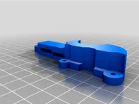
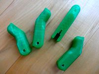
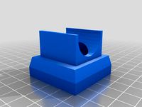
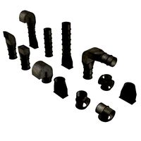
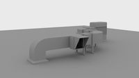
Dave's Upgraded E3Dv6 Fan Duct by orgemd
by Thingiverse
Last crawled date: 2 years, 12 months ago
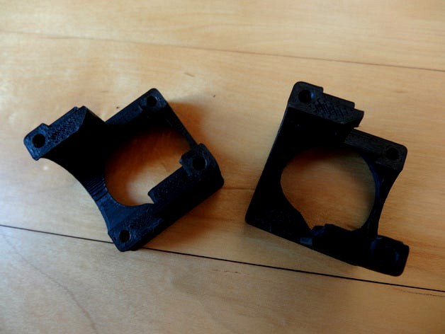
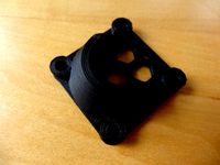
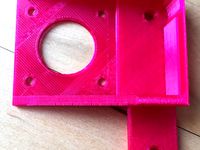
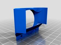
I have been moving towards using the E3Dv6 hotend for my printer. Since I print ABS, however, I have concerns about the active cooling this hotend requires. I therefore wanted a way to duct both the intake and outlet of that cooling - minimizing the possibility of drafts impacting the printing. The stock E3Dv6 fan duct does not allow for that. I found thing 375419 by rmoncello, and thought it was a brilliant, beautiful solution. When I printed it, however, I had some issues. In particular:
the central hole was slightly too small for the heatsink so that the parts would not completely close
even if the central hole was correct, a lot of air was going to escape out the seams
the fan hole was not constrained to the cooling fins so that a lot of air could escape
the model did not seem to account for the slightly different size of the bottom fin
although the part had nice looking curves, those curves made it harder to get a good clean print
screw holes were too small and shallow - requiring hand drilling - and had no way to link the two halves together
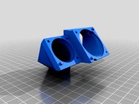
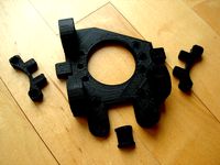
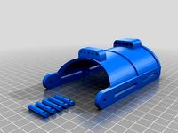
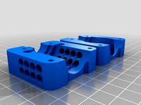
For this version, I made the following adjustments:
I adjusted the central hole size to better fit my heatsink and made an allowance for the larger bottom fin - with a choice to make the top of the duct flush with the top fin of the heatsink, or the bottom of the duct flush with the bottom fin of the heatsink.
I adjusted the fan hole to limit flow through the fins - again with a choice of if the duct sits aligned to the top or bottom.
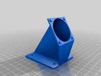
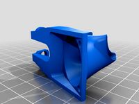
I simplified the shape to improve printability.
I added overlapping ridges to better seal the seams between the two parts.
I adjusted the screw hole diameter and depth to better allow tapping of those holes, and made it possible to link the parts with screws through one part and into the other.
This version is available as an OpenSCAD script so that modifications can be made as needed. I have not exposed a lot of parameters. The only easy changes in the SCAD are the size of the screw holes and whether the alignment should be to the top or the bottom. More modifications can be made, however, with a bit of OpenSCAD knowledge.
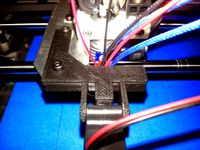
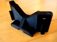
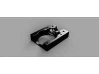
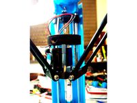
Update - 2014-09-09 - Having assembled the full hotend, the version that aligns with the bottom fin works great, but I would not recommend the version that aligns with the top fin. The printed part would have to be right on top of the heater block - if it would even fit. I might look at it a bit to see if maybe I can do something to open up a bit of space there in the future.
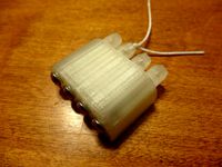
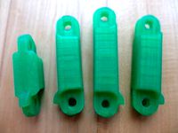
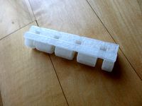
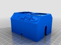
Update - 2014-10-05 - I have uploaded a new Update2 version. This is to fix the issue when trying to align to the top of the top fin on the heat sink. I would not recommend doing this. I would recommend aligning to the bottom fin. Otherwise, the duct is close to the heater block. If, however, you want to align to the top, this carves a space for the heater block and also allows a parametric stretch of one or both parts of the duct to make room. In the pictures, I used a stretch of 0 on one half, and 5mm on the other half. I would still use 0 stretch on ducts aligned to the bottom. The scad now draws both halves at once.
the central hole was slightly too small for the heatsink so that the parts would not completely close
even if the central hole was correct, a lot of air was going to escape out the seams
the fan hole was not constrained to the cooling fins so that a lot of air could escape
the model did not seem to account for the slightly different size of the bottom fin
although the part had nice looking curves, those curves made it harder to get a good clean print
screw holes were too small and shallow - requiring hand drilling - and had no way to link the two halves together
For this version, I made the following adjustments:
I adjusted the central hole size to better fit my heatsink and made an allowance for the larger bottom fin - with a choice to make the top of the duct flush with the top fin of the heatsink, or the bottom of the duct flush with the bottom fin of the heatsink.
I adjusted the fan hole to limit flow through the fins - again with a choice of if the duct sits aligned to the top or bottom.
I simplified the shape to improve printability.
I added overlapping ridges to better seal the seams between the two parts.
I adjusted the screw hole diameter and depth to better allow tapping of those holes, and made it possible to link the parts with screws through one part and into the other.
This version is available as an OpenSCAD script so that modifications can be made as needed. I have not exposed a lot of parameters. The only easy changes in the SCAD are the size of the screw holes and whether the alignment should be to the top or the bottom. More modifications can be made, however, with a bit of OpenSCAD knowledge.
Update - 2014-09-09 - Having assembled the full hotend, the version that aligns with the bottom fin works great, but I would not recommend the version that aligns with the top fin. The printed part would have to be right on top of the heater block - if it would even fit. I might look at it a bit to see if maybe I can do something to open up a bit of space there in the future.
Update - 2014-10-05 - I have uploaded a new Update2 version. This is to fix the issue when trying to align to the top of the top fin on the heat sink. I would not recommend doing this. I would recommend aligning to the bottom fin. Otherwise, the duct is close to the heater block. If, however, you want to align to the top, this carves a space for the heater block and also allows a parametric stretch of one or both parts of the duct to make room. In the pictures, I used a stretch of 0 on one half, and 5mm on the other half. I would still use 0 stretch on ducts aligned to the bottom. The scad now draws both halves at once.
Similar models
thingiverse
free
E3Dv6 Shroud mounted fan ducts - 40mm heatsink and 30mm print fans by bugr
...usted up or down on the heat sink but add some aluminium foil tape to area above heat block if needs to be lower for your setup.
thingiverse
free

Kossel Delta effector E3Dv6 hotend fan and part cooling thingie by 3DFreezeMe
...g enough in the middle, the top ring of the e3dv6 heatsink will need to fit in it.
i used:http://www.thingiverse.com/thing:642167
thingiverse
free
Intake Duct for Controller Cooling Fan by ArtieH
...rsion 2: screw holes allow the attachment of the intake duct through the mounting holes of the fan into the stepper cooling duct.
thingiverse
free
Anet A8 Ultimate Fan Duct Remix by WolvenScout
...also tapered the sides of the rounded top down to the bottom, so there is no overhang on that portion, as well as added strength.
thingiverse
free
adjustable stock fan duct by Thumper72
...3dv6 and also the volcano version of the e3dv6.. i do use a bmg as a extruder and removed the stock metal shroud to save weight..
thingiverse
free
Part Fan Mount for Rigidbot with E3Dv6 hotend by roseundy
...50mm blower as a part fan to a rigidbot that is using a (lossy) e3dv6 hotend. i have also included a duct to direct the airflow.
thingiverse
free
K8400 Hotend Fan Duct by gigl
...iverse.com/thing:1196270
however to better mount it, i have added screw holes at the top.
now it sits really stable in my printer
thingiverse
free
Fan Duct for Anycubic i3 Mega with V6 Hotend by GrEy3001
...orter v6 hotend.
i recommend to print this like uploaded with supports outside the airchannel, set support angle to 50° or lower.
thingiverse
free

Universal E3DV6 40mm fan duct by sortik
...erse
remix of universal e3dv6 fan duct for 40 mm fans. i also made one version that has bigger hole with better stronger airflow
thingiverse
free
Dave's 30mm E3Dv6 fan intake duct by orgemd
...part). that is just about perfect. you can adjust the plate thickness or the standoff to accommodate something else, if needed.
Orgemd
thingiverse
free
Dave's Parametric X-Carriage for Self-Aligning Bushings by orgemd
...erse
this is an openscad file to allow the selection of multiple options in creating an x-carriage for reprap style 3d printers.
thingiverse
free
Parametric Cable Tensioner by orgemd
...otion after full closure. to accommodate that, i slightly changed some of the dimensions and added a shell to cover the springs.
thingiverse
free
Dave's Modified AO Z-Upper Mount by orgemd
...nal brace as well as portions that slide into the aluminum extrusions. i am using the modified versions on my mendelmax printer.
thingiverse
free
Titan Mount by orgemd
...play with the values a bit to make room. should be an easy fix, but i don't yet know the correct separation to make it work.
thingiverse
free

Parametric Finger v2 by orgemd
... those are more examples than anything else. i am a big believer in taking the time to customize each finger to your own needs.
thingiverse
free
Parametric Gauntlet by orgemd
...e off the print bed. that makes the parts print much better, but requires a bit of filing or sanding to round the part back out.
thingiverse
free
Parametric Proximal Phalange by orgemd
...t it will be helpful for others. if, however, you intend to use it, seek appropriate medical attention from a trained physician.
thingiverse
free
Parametric Knuckle Block by orgemd
...at it will be helpful for others. if, however, you intend to use it, seek appropriate medical attention from a trained physician.
thingiverse
free
Parametric Distal Phalange by orgemd
...at it will be helpful for others. if, however, you intend to use it, seek appropriate medical attention from a trained physician.
thingiverse
free
Dave's 30mm E3Dv6 fan intake duct by orgemd
...part). that is just about perfect. you can adjust the plate thickness or the standoff to accommodate something else, if needed.
Dave
3d_export
$15

Cyborg Dave
...cyborg dave
3dexport
cyborg dave from a parallel universe
turbosquid
$2

Crazy Dave
...bosquid
royalty free 3d model crazy dave for download as fbx on turbosquid: 3d models for games, architecture, videos. (1178843)
turbosquid
free

dave valve
...bosquid
free 3d model dave valve for download as dwg and stl on turbosquid: 3d models for games, architecture, videos. (1531462)
turbosquid
$20
Tosconova Dave
...alty free 3d model tosconova dave for download as max and fbx on turbosquid: 3d models for games, architecture, videos. (1343864)
turbosquid
$30

Winter Dave
... available on turbo squid, the world's leading provider of digital 3d models for visualization, films, television, and games.
3ddd
$1
Dave Shield Wood Table
...dave shield wood table
3ddd
журнальный
dave shield wood modern table
turbosquid
$8

Dave Table Lamp
... model dave table lamp for download as max, max, fbx, and obj on turbosquid: 3d models for games, architecture, videos. (1659415)
turbosquid
$20

Dave the hairy monster
... available on turbo squid, the world's leading provider of digital 3d models for visualization, films, television, and games.
turbosquid
free

Daves basketball court.max
... available on turbo squid, the world's leading provider of digital 3d models for visualization, films, television, and games.
3ddd
$1
Calia Italia DAVE. 852
...dave. 852
3ddd
dave
ссылка на сайт производителя:http://www.caliaitalia.com/en/categorie-collezioni/emporio/#ad-image-2
E3Dv6
thingiverse
free
Dualfan for e3dv6 by CaJI9I
...dualfan for e3dv6 by caji9i
thingiverse
this fan for dual extruder e3dv6. spacing between nozzle 24 mm
thingiverse
free
e3dv6 mount remix by mokash770
...e3dv6 mount remix by mokash770
thingiverse
e3dv6 mount with bigger holes repired
thingiverse
free
E3Dv6 Bowden Clamp by x20011
...e3dv6 bowden clamp by x20011
thingiverse
this is a e3dv6 hotend clamp with an additional 40x40mm fan mount.
thingiverse
free
E3DV6 by makermitch69
...e3dv6 by makermitch69
thingiverse
this includes a custom cover for the anet a8 with a place for 4 leds
thingiverse
free
e3dv6 gran caudal 40mm by jj25000
...e3dv6 gran caudal 40mm by jj25000
thingiverse
e3dv6 ventilador 40x40
thingiverse
free
support e3dv6 + titan + bltouch by nikos1234
...support e3dv6 + titan + bltouch by nikos1234
thingiverse
support e3dv6 + titan + bltouch
thingiverse
free
E3dV6 fan 4040 by andreascarpelli
...040 by andreascarpelli
thingiverse
this is a design to have a single fan on a e3dv6 that fit a 4cm fan for extruder and hot end
thingiverse
free

e3dv6 fan duct by Snorkis
...r this e3dv6 mount https://www.thingiverse.com/thing:2790694?fbclid=iwar19pbsfb39c7m0kvpxb-f_wh3i_uoxl43d5ghoedarbmfezc-vwr01nnia
thingiverse
free

E3Dv6 mount for Renkforce RF500 by Timon_Suhk
...e3dv6 mount for renkforce rf500 by timon_suhk
thingiverse
two piece mount for e3dv6 on renkforce rf500.
thingiverse
free
E3Dv6 for 101 Hero by electrokill
...electrokill
thingiverse
wip
heres a mount for an e3dv6 for a 101 hero
other customizations follow so here is only the first part
Duct
turbosquid
$19
Duct Set
...d
royalty free 3d model duct set for download as max and fbx on turbosquid: 3d models for games, architecture, videos. (1145038)
turbosquid
$10
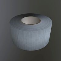
Duct Tape
...id
royalty free 3d model duct tape for download as ma and ma on turbosquid: 3d models for games, architecture, videos. (1580351)
turbosquid
free
Duct Tape
...
free 3d model duct tape for download as obj, fbx, and blend on turbosquid: 3d models for games, architecture, videos. (1486518)
3d_ocean
$7
Air-duct
... ventilation
high quality industrial air duct ventilation model. created in cinema 4d but comes in various other formats as well.
turbosquid
$20
Air ducts
...lty free 3d model air ducts for download as max, obj, and fbx on turbosquid: 3d models for games, architecture, videos. (1262476)
3d_export
$10
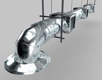
Supply air duct
...supply air duct
3dexport
supply air duct with two axial fans and hangers
turbosquid
$2
Duct Tape
...e 3d model duct tape for download as obj, fbx, blend, and dae on turbosquid: 3d models for games, architecture, videos. (1473972)
turbosquid
free
Duct Tape
... available on turbo squid, the world's leading provider of digital 3d models for visualization, films, television, and games.
3d_ocean
$3
Duct tape
...polys. includes: cinema 4d project. model in 3 formats (obj, fbx, 3ds). 6 .tga texture maps (albedo, ambient occlusion, diffus...
turbosquid
$40
Ventilation Duct PACK
...tion duct pack for download as ma, obj, fbx, and unitypackage on turbosquid: 3d models for games, architecture, videos. (1287068)
Upgraded
turbosquid
$15
Upgraded Glock
...e 3d model upgraded glock for download as obj, fbx, and blend on turbosquid: 3d models for games, architecture, videos. (1185950)
3ddd
$1
Calligaris / UPGRADE
...calligaris / upgrade
3ddd
calligaris
c материалом
3d_export
free
cz upgrade
...cz upgrade
3dexport
https://www.buymeacoffee.com/mestrezen3d https://linktr.ee/mestrezen3
turbosquid
$80
Custer Tank upgrade
... available on turbo squid, the world's leading provider of digital 3d models for visualization, films, television, and games.
turbosquid
$39

Domestos 1 upgrade
... available on turbo squid, the world's leading provider of digital 3d models for visualization, films, television, and games.
3d_export
$10

Upgraded tea cup
...upgraded tea cup
3dexport
a cup with an unusual design and a unique shape for a more enjoyable tea experience
3d_export
$8

dixy outlander classic style upgraded poplar wood lounge chair
...utlander classic style upgraded poplar wood lounge chair
3dexport
dixy outlander classic style upgraded poplar wood lounge chair
turbosquid
free

AK-12 + Upgrades low-poly 3D model
...ow-poly 3d model for download as fbx, blend, and unitypackage on turbosquid: 3d models for games, architecture, videos. (1501145)
evermotion
$700

Upgrade from V-ray 1.5 to 3.5 for 3ds max
...here is no need to purchase a new dongle - your current dongles will be reprogrammed to carry v-ray 3. evermotion 3d models shop.
evermotion
$300

Upgrade from V-Ray 2.0 to V-ray 3.5 for 3ds Max
... interface (gui) for editing settings on one machine and one render node for rendering on one machine. evermotion 3d models shop.
Fan
3d_export
$5
fan
...fan
3dexport
fan 3d model, table fan, fan, electric fan, ventilator
archibase_planet
free

Fan
...fan
archibase planet
fan large fan
fan out n260707 - 3d model for interior 3d visualization.
archibase_planet
free
Fan
...fan
archibase planet
fan ceiling fan ventilator
fan stealth n300615 - 3d model (*.gsm+*.3ds) for interior 3d visualization.
3d_export
$15

fan
...fan
3dexport
is an ancient fan
3ddd
$1
Fan-C-Fan by marco gallegos
...n-c-fan by marco gallegos
3ddd
вентилятор , marco gallegos
fan-c-fan by marco gallegos
3d_export
$10
fan
...fan
3dexport
a detailed fan designed for home or space blowing is now available for only 19.99!
turbosquid
$1
Fan
...fan
turbosquid
free 3d model fan for download as on turbosquid: 3d models for games, architecture, videos. (1427865)
turbosquid
$14

Fan
...fan
turbosquid
royalty free 3d model fan for download as on turbosquid: 3d models for games, architecture, videos. (1415642)
3ddd
$1

Светильник Fan
...светильник fan
3ddd
fan , italamp
светильник fan, производитель italamp
turbosquid
$25

Fan
...fan
turbosquid
royalty free 3d model fan for download as c4d on turbosquid: 3d models for games, architecture, videos. (1483246)