Thingiverse
D300VS Barbell Carriage and Effector Set by Velocitasfortis
by Thingiverse
Last crawled date: 3 years ago
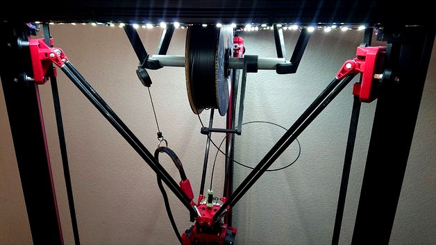
This is a ball-cup arm upgrade set for the Ultibots D300VS, for use with Trick Laser/SeeMeCNC fixed-width barbells and Trick Laser Ball-Cup Arms, as well as the stock Ultibots micro extruder. It should be possible to use this set with other Kossel Delta printers using standard 2020 or 2040 extrusions for the towers (aligned edge-on to the build surface), as long as the Ultibots micro extruder is being used for the hotend. For the D300VS, use of Ultibots 375mm ball-cup arms is standard, but any arms 340-400mm should work. For other deltas, you will need to determine your own best rod length. YMMV
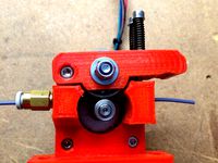
Carriages are designed to make use of Open Builds eccentric spacers on the single tensioning axle. This requires the use of an Open Builds standard 3mm wheel spacer stacked on top of the eccentric spacer, and standard 9mm axle spacers for the other two wheels on each carriage. Also, the pocket for the eccentric spacer is quite tight to the spacer, for rigidity and reliability purposes. You will want to thread the M5 axle bolt through the hole, slip on the eccentric spacer, 3mm spacer, wheel assembly, and then use the M5 nut to tighten everything down and force the eccentric into the pocket.
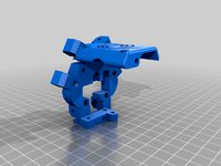
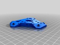
Effector platform should fit without modification to the extruder body, but if you do notice any clearance issues where one barbell comes into contact with the top of one corner, simply file the corner of the extruder body for clearance - the section of the extruder where the barbell might impinge is a non-critical area (just above and forward of the idler bearings). On one of my extruder bodies, everything fit flush and good, while on another I had to run a couple passes of a file across the corner to make a very shallow pocket. This could be alleviated by either making the effector thicker, moving the bolt holes for the barbells up a smidge, or making the effector platform a bit wider, but none of these changes are ideal for the overall geometry. EDIT: I have uploaded the original FreeCAD .FCStd and exported STEP file for the effector block, so that people can make adjustments for non-Ultibots extruders in the CAD program of their choice. The FCStd file will obviously only work in FreeCAD, but will give you the original annotated workflow for editing (keep an eye out for wandering sketches, as tends to happen in FreeCAD). The STEP file will give you a solid to rework. This is all mostly for absolute measurement purposes.
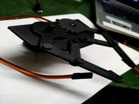
Belts should be wrapped snugly around the belt locking grooves, as pictured. Wrapping the first turn fairly tightly helps support the belt tension (I only left three exposed teeth around the first bend on both the top block and the bottom, as pictured although it can be difficult to see due to Thingiverse image scaling). Slots in effector are sized for 2mm GT2 belts.
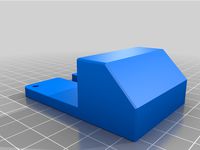
Bottom tensioner block requires the use of a 30mm M3 cap screw. Shorter screws can be used, but you will lose adjustment range.
Each carriage needs the following hardware:
1x M3x30 cap screw
2x M3x10 cap screw
3x M3 washer
3x M3 nut
3x M5x35 low-profile cap screw
2x M5x9 spacer(Open Builds link below)
1x M5x6 eccentric spacer (Open Builds link below)
1x M5x3 spacer (Open Builds link below)
3x V-Slot wheel (Open Builds link below)
3x M5 nut (nylock nuts preferred, or the use of thread locker is suggested)
1x Trick Laser/SeeMeCNC 50mm barbell (either should work, but these are made specifically for the TL billet barbells - link below)
Effector requires the following hardware:
6x M3x10 cap screw
6x M3 nut
8x M3 washer
2x M3x15 cap screw (due to printing variation and setup, slightly longer screws might be needed)
3x Trick Laser/SeeMeCNC 50mm barbell (same caveat as before)
And of course, you'll need an appropriate-length set of ball-cup arms... (Ultibots link below for people with a D300VS)
Assembly tip: The belt does need to be threaded behind the barbell on each carriage, so it's best to hook the belt through the top catch block, run it over the top pulley, then run the free end through the belt channel prior to hooking it through the bottom adjustment block. This should be fairly self-explanatory with the provided pictures.
When all is completed, be sure to adjust your delta arm length, delta radius/effector offset, reset the bed zero point (paper snag test), and give the machine some extra headroom in the firmware prior to running calibration - nobody likes head crashes.
Parts as pictured printed in Proto-Pasta HTPLA V3 as prototypes. PLA is functional for non-heated printers (can be enclosed, just not heated - build plate itself can be heated), but will warp badly if exposed to heat, as the carriages are under quite a bit of tension. Suggest using ABS-PC alloy, CF-ABS composite, or CF-Nylon composite for final parts.
Links to parts used in this build:
Trick Laser billet barbells - https://www.seemecnc.com/collections/parts-accessories/products/cnc-machined-ball-joint-kit
V-Slot Wheels - https://openbuildspartstore.com/solid-v-wheel-kit/
Eccentric spacer - https://openbuildspartstore.com/eccentric-spacer/ (be sure to select 6mm)
Aluminum spacers - https://openbuildspartstore.com/aluminum-spacers-10-pack/ (be sure to select both 3mm and 9mm)
Ball-cup arms - https://www.ultibots.com/trick-laser-ball-cup-arm-set-375mm/
OPTIONAL: I use 2mm metal grommets as filament chases, as CF-filled filaments can erode printed parts as they are pulled through. This grommet can be seen in the top-down picture of the effector platform. If you'd like to add some durability and improved finish to parts, I use these (I am not in any way affiliated with this product - I just like it), https://www.amazon.com/gp/product/B071L8HJNW/
Carriages are designed to make use of Open Builds eccentric spacers on the single tensioning axle. This requires the use of an Open Builds standard 3mm wheel spacer stacked on top of the eccentric spacer, and standard 9mm axle spacers for the other two wheels on each carriage. Also, the pocket for the eccentric spacer is quite tight to the spacer, for rigidity and reliability purposes. You will want to thread the M5 axle bolt through the hole, slip on the eccentric spacer, 3mm spacer, wheel assembly, and then use the M5 nut to tighten everything down and force the eccentric into the pocket.
Effector platform should fit without modification to the extruder body, but if you do notice any clearance issues where one barbell comes into contact with the top of one corner, simply file the corner of the extruder body for clearance - the section of the extruder where the barbell might impinge is a non-critical area (just above and forward of the idler bearings). On one of my extruder bodies, everything fit flush and good, while on another I had to run a couple passes of a file across the corner to make a very shallow pocket. This could be alleviated by either making the effector thicker, moving the bolt holes for the barbells up a smidge, or making the effector platform a bit wider, but none of these changes are ideal for the overall geometry. EDIT: I have uploaded the original FreeCAD .FCStd and exported STEP file for the effector block, so that people can make adjustments for non-Ultibots extruders in the CAD program of their choice. The FCStd file will obviously only work in FreeCAD, but will give you the original annotated workflow for editing (keep an eye out for wandering sketches, as tends to happen in FreeCAD). The STEP file will give you a solid to rework. This is all mostly for absolute measurement purposes.
Belts should be wrapped snugly around the belt locking grooves, as pictured. Wrapping the first turn fairly tightly helps support the belt tension (I only left three exposed teeth around the first bend on both the top block and the bottom, as pictured although it can be difficult to see due to Thingiverse image scaling). Slots in effector are sized for 2mm GT2 belts.
Bottom tensioner block requires the use of a 30mm M3 cap screw. Shorter screws can be used, but you will lose adjustment range.
Each carriage needs the following hardware:
1x M3x30 cap screw
2x M3x10 cap screw
3x M3 washer
3x M3 nut
3x M5x35 low-profile cap screw
2x M5x9 spacer(Open Builds link below)
1x M5x6 eccentric spacer (Open Builds link below)
1x M5x3 spacer (Open Builds link below)
3x V-Slot wheel (Open Builds link below)
3x M5 nut (nylock nuts preferred, or the use of thread locker is suggested)
1x Trick Laser/SeeMeCNC 50mm barbell (either should work, but these are made specifically for the TL billet barbells - link below)
Effector requires the following hardware:
6x M3x10 cap screw
6x M3 nut
8x M3 washer
2x M3x15 cap screw (due to printing variation and setup, slightly longer screws might be needed)
3x Trick Laser/SeeMeCNC 50mm barbell (same caveat as before)
And of course, you'll need an appropriate-length set of ball-cup arms... (Ultibots link below for people with a D300VS)
Assembly tip: The belt does need to be threaded behind the barbell on each carriage, so it's best to hook the belt through the top catch block, run it over the top pulley, then run the free end through the belt channel prior to hooking it through the bottom adjustment block. This should be fairly self-explanatory with the provided pictures.
When all is completed, be sure to adjust your delta arm length, delta radius/effector offset, reset the bed zero point (paper snag test), and give the machine some extra headroom in the firmware prior to running calibration - nobody likes head crashes.
Parts as pictured printed in Proto-Pasta HTPLA V3 as prototypes. PLA is functional for non-heated printers (can be enclosed, just not heated - build plate itself can be heated), but will warp badly if exposed to heat, as the carriages are under quite a bit of tension. Suggest using ABS-PC alloy, CF-ABS composite, or CF-Nylon composite for final parts.
Links to parts used in this build:
Trick Laser billet barbells - https://www.seemecnc.com/collections/parts-accessories/products/cnc-machined-ball-joint-kit
V-Slot Wheels - https://openbuildspartstore.com/solid-v-wheel-kit/
Eccentric spacer - https://openbuildspartstore.com/eccentric-spacer/ (be sure to select 6mm)
Aluminum spacers - https://openbuildspartstore.com/aluminum-spacers-10-pack/ (be sure to select both 3mm and 9mm)
Ball-cup arms - https://www.ultibots.com/trick-laser-ball-cup-arm-set-375mm/
OPTIONAL: I use 2mm metal grommets as filament chases, as CF-filled filaments can erode printed parts as they are pulled through. This grommet can be seen in the top-down picture of the effector platform. If you'd like to add some durability and improved finish to parts, I use these (I am not in any way affiliated with this product - I just like it), https://www.amazon.com/gp/product/B071L8HJNW/
Similar models
thingiverse
free

MGN12 SeeMeCNC Barbell Carriage for Delta Printer (D300VS and others)
...ails when mounting them.
also check out my hemera mount that also uses seemecnc barbellshttps://www.thingiverse.com/thing:4027625
thingiverse
free

55mm Magball Carriage & Effector for D300VS+
... of the effector in order to allow easier access to the titan aero (or titan extruder.) this makes assembly and cleaning easier.
thingiverse
free

2020 Carriages for Zero-Backlash Magnetic Arms by huntley
...by about 50 microns.
i also have a version for 15mm diameter "mini" v-wheels: http://www.thingiverse.com/thing:2183355
thingiverse
free

D300VS Thickened Barbell Carriages
...them to work.
another good mod would be to move the tensioning mechanism over to the side with the two wheels for more stability.
thingiverse
free

Effector and carriages for D300VS+ (Aero Titan) for Haydn Huntley's Magball Arms by artoonie
...you'll need to be able to adjust in on the carriages.
print 3x of each of:
the belt wedge
the carriage tensioner
carriage.stl
thingiverse
free

Duet Smart Effector 2020 Carriage by mfoltz
.... this is meant for 24mm diameter derlin wheels with an eccentric spacer. also has gt2 6mm belt tensioner that takes 3mm hardware
thingiverse
free

Bowden 1.75mm Extruder Reducer by Trigubovich
...ring (5x16x5)
1x m5x20 cap screw
1x m5 nut
4x m3x25 cap screw
1x m3 nut
if you do not want to use support material, use cut parts
thingiverse
free

Delta Carriage for 2020 Aluminum V-Slot® 20x20 Linear Rail by quadcells
...near the top of the carriage for the end stop adjusting bolt and one to lock down the end stop adjusting bolt (see the pictures).
thingiverse
free

east3D gecko coreXY Z-wheel-carriage by delukart
...slight resistance ) finaly tighten the carriages to the z stage.
(i do advise to relevel and retighten the z belts at this time.)
thingiverse
free
Mini Kossel 1.75mm extruder by wallie
...et head cap screw
2x spring
1x m5 pneumatic straight threaded-to-tube adapter, push in 4 mm 4mm male
tools
m5 manual screw tap
Velocitasfortis
thingiverse
free

Paint Palette by Velocitasfortis
...paint palette by velocitasfortis
thingiverse
simple palette with brush holder. mixing pockets are 2mm deep.
thingiverse
free

Coaster Caddy by Velocitasfortis
...ephant's foot.
model updated with different base dimensions to improve rigidity. should still hold the same vertical volume.
thingiverse
free

Paint Caddy for Testors Jars by Velocitasfortis
...ell as assorted items (brushes, glue, etc.).
bottom of model has 0.20mm chamfer and pockets to ease release from the build plate.
thingiverse
free

Drafting Caddy by Velocitasfortis
...ottom of model is lightly chamfered and pocketed to ease release from the build plate, and to compensate for elephant's foot.
thingiverse
free

Printer Belt Lock by Velocitasfortis
...o be spinning the motor all over, generating current into your driver board. slips into place and prevents the axis from moving.
thingiverse
free

Toilet Seat Replacement Pads by Velocitasfortis
...the seat or lid from more than an inch or two. no physical danger, but quite annoying. pla will shatter and should not be used.
thingiverse
free

Gift Box Ornaments by Velocitasfortis
...inor overhangs w/filleting, simple flower-bow with moderate rise angle. prints well in pla and asa (other filaments not tested).
thingiverse
free

Window Security Rod Hardware by Velocitasfortis
...ailable 3/4" square stock. pla does work, but abs/asa or nylon are recommended, as window jambs can get very hot in summer.
thingiverse
free

Filament Calibration Jig for Prusa i3 Mk3 by Velocitasfortis
...e irrelevant, as my test results showed that prusa has the extruder tuned bang-on from the factory, but i figured i'd share.
thingiverse
free

Allen Key Socket Adapter by Velocitasfortis
... for turning by hand.
filament costs pennies, while long-reach 3/8" drive allen wrenches cost dollars. ;)
update: 3mm added
D300Vs
thingiverse
free
E3D Hemera delta mount (D300VS/D300VS+)
...rest is as the original. print upside down with support. and don't look at my wiring, it was only mounted for a short test ;)
thingiverse
free

D300vs cable guide by stavrosg
...ade one for my cr-10, adapted it for my delta ,an ultibots d300vs+
added a 60mm taller version that handled my 450mm delta better
thingiverse
free

D300VS+ Dust Covers by Lucidwolf
...vertical slot based delta printers.
this is part of my upgrades to the ultibots d300vs+ https://www.thingiverse.com/thing:3089764
thingiverse
free

D300VS+ Modifications by Lucidwolf
...printers speed limit.
like most printers this is a work in progress.
still need to design and print
1.) led holders
2.) enclosure
thingiverse
free

D300VS Directed Airflow Part Cooler by hardrocker
...mm blower fans with no changes required for the wiring. the design requires (6) m3x25mm screws and (6) m3 nuts for installation.
thingiverse
free
D300VS Thickened Barbell Carriages
...them to work.
another good mod would be to move the tensioning mechanism over to the side with the two wheels for more stability.
thingiverse
free

UltiBots D300VS Filament Guide by SublimeLayers
...imelayers
thingiverse
this is a filament guide that helps prevent filament from unspooling when the printer homes after a print.
thingiverse
free
55mm Magball Carriage & Effector for D300VS+
... of the effector in order to allow easier access to the titan aero (or titan extruder.) this makes assembly and cleaning easier.
thingiverse
free

UltiBots D300VS 3D Printer by Verohomie
...
d300vs bom is located here https://docs.google.com/spreadsheets/d/13qilrma5xjv6fmad4rimuzotkzjiyf5niunzzmn20gm/edit?usp=sharing
thingiverse
free
Tusk Fan for D300VS+ magball edition
...erse.com/thing:2223113/ effector :)
source here https://www.sublimelayers.com/2017/10/tusk-part-cooling-for-titan-aero-and.html
Barbell
archibase_planet
free

Barbell
...barbell
archibase planet
weight barbell gym equipment
barbell n090311 - 3d model (*.3ds) for interior 3d visualization.
archibase_planet
free

Barbell
...arbell
archibase planet
barbell bar weight crossbar
barbell rogue n230316 - 3d model (*.gsm+*.3ds) for interior 3d visualization.
archibase_planet
free

Barbell
...barbell
archibase planet
barbell weight gym equipment
barbell stand gym n160411 - 3d model (*.3ds) for interior 3d visualization.
3d_export
$5

barbell
...barbell
3dexport
barbell ø 74 × 80 cm polys: 80 540 verts: 81 959 https://ru.lampachn.com/barbell-p0491.html
turbosquid
$12

Barbell
...uid
royalty free 3d model barbell for download as ma and fbx on turbosquid: 3d models for games, architecture, videos. (1558241)
turbosquid
$5

Barbell
...
royalty free 3d model barbell for download as blend and obj on turbosquid: 3d models for games, architecture, videos. (1657837)
turbosquid
$35

Barbell
...yalty free 3d model barbell for download as 3ds, max, and obj on turbosquid: 3d models for games, architecture, videos. (1302398)
3d_export
$5

bench with a barbell
...bench with a barbell
3dexport
weight bench with a barbell. trainer for weightlifting.
turbosquid
$20

Barbell
... available on turbo squid, the world's leading provider of digital 3d models for visualization, films, television, and games.
turbosquid
$19

barbell
... available on turbo squid, the world's leading provider of digital 3d models for visualization, films, television, and games.
Effector
3d_ocean
$5

Radial Sound Effector
...e spheres will expand with your song. fully customisable, change the color, the size of the spheres or even put in different s...
3d_ocean
$12
3D Customizable Puzzle Set (16x10)
...mograph compatible (you can effect the pieces with mograph effector) - included also a non-mograph version with...
thingiverse
free
Effector by olo2000pm
...effector by olo2000pm
thingiverse
effector
thingiverse
free
CERAMBOT-Effector
...cerambot-effector
thingiverse
cerambot-effector
thingiverse
free

modulize effector by candyasdf
...ulize effector by candyasdf
thingiverse
mount things on effector with m3 screws
effector radius : 25.4mm
rod arm distance : 40mm
thingiverse
free
Delta Effector by zavier
...delta effector by zavier
thingiverse
delta effector with radial fan 50 and bltouch
thingiverse
free
D810 Effector by WhiteTiger13
...d810 effector by whitetiger13
thingiverse
this is d810 effector for d810 without autocalibration, and also cap for it.
thingiverse
free
Effector for Delta Printer
...effector for delta printer
thingiverse
effector for delta printer (3 color)
using diamond hotend
thingiverse
free
Delta effector magnetic by fpassos
...delta effector magnetic by fpassos
thingiverse
effector for e3dv6 hotend. i needed put the spheres (10mm) on the effector.
thingiverse
free
End Effector Gripper
...end effector gripper
thingiverse
end effector gripper
for a robotic arm
uses mg995 servo motor
Carriage
archibase_planet
free
Carriage
...arriage
archibase planet
perambulator baby carriage pram
carriage n250908 - 3d model (*.gsm+*.3ds) for interior 3d visualization.
3d_export
free
carriage
...carriage
3dexport
old fashion carriage model, more files here:
turbosquid
$140
Carriage
...urbosquid
royalty free 3d model carriage for download as max on turbosquid: 3d models for games, architecture, videos. (1482052)
turbosquid
$25
Carriage
...urbosquid
royalty free 3d model carriage for download as max on turbosquid: 3d models for games, architecture, videos. (1285944)
3d_export
free
carriage
...carriage
3dexport
game cart
3d_ocean
$15
Barrel Carriage
...ieval oak old transport wheels wine wood
this model contains a barrel and a carriage. it is a medieval type of wood oak carriage.
turbosquid
$40
Carriage
...ty free 3d model carriage for download as obj, fbx, and blend on turbosquid: 3d models for games, architecture, videos. (1290094)
turbosquid
free
Carriage
...yalty free 3d model carriage for download as ma, obj, and fbx on turbosquid: 3d models for games, architecture, videos. (1239157)
3d_export
$5
Medieval carriage
...medieval carriage
3dexport
medieval carriage in fairy style
turbosquid
$58

Carriage
...d model carriage with scene for download as max, obj, and fbx on turbosquid: 3d models for games, architecture, videos. (1276262)
Set
archibase_planet
free
Setting
...setting
archibase planet
setting cover place setting
setting - 3d model (*.gsm+*.3ds) for interior 3d visualization.
archibase_planet
free
Setting
...setting
archibase planet
setting place setting cover
setting - 3d model (*.gsm+*.3ds) for interior 3d visualization.
archibase_planet
free

Setting
...setting
archibase planet
setting place setting cover
setting - 3d model (*.gsm+*.3ds) for interior 3d visualization.
3d_export
$8

decorative set mens set
...decorative set mens set
3dexport
decorative set men's set
archibase_planet
free
Set
...anet
set kitchen ware kitchen set kitchen tools
set kitchen tools n281114 - 3d model (*.gsm+*.3ds) for interior 3d visualization.
archibase_planet
free
Set
...set
archibase planet
beer set bar equipment
beer set - 3d model for interior 3d visualization.
archibase_planet
free
Set
...set
archibase planet
cover place setting
set - 3d model (*.gsm+*.3ds) for interior 3d visualization.
archibase_planet
free
Set
...set
archibase planet
kitchen set kitchen ware
set - 3d model (*.gsm+*.3ds) for interior 3d visualization.
archibase_planet
free
Set
...set
archibase planet
set cup glass kitchen ware
set - 3d model (*.gsm+*.3ds) for interior 3d visualization.
archibase_planet
free
Set
...set
archibase planet
flatware cover place setting
set n311210 - 3d model (*.gsm+*.3ds) for interior 3d visualization.