Thingiverse
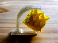
Cyclops flippy bot by GeoDave
by Thingiverse
Last crawled date: 3 years ago
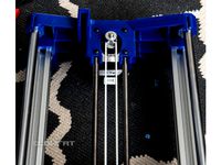
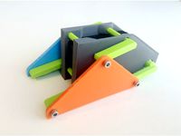
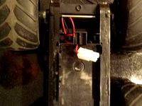
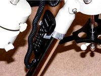
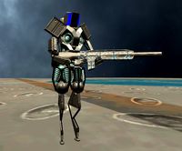
I could not leave well enough alone as looking at this design was just hollering for a cyclops eye on the front. I have quite a few of these eyes left over from the hungry bot project. I made the body as one piece to cover up the electrical wires more & used plastic 3d printed screws & 2 - 4" wire ties, so there the only hardware needed is the motor, battery case & batteries. I could cut down the weight on the body some by adding big holes in the side, bottom & back & putting tape over the holes. The threading idea I took from gzumwalt's hummingbird design (https://www.thingiverse.com/thing:2859291).
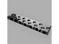
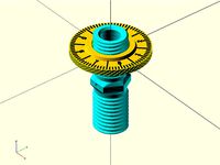
The threaded parts I used are M6 threading and a mating gap of 0.4mm. I print the threaded portions of the parts at .1mm. To modify any of the openscad files that use the threading, you will need to download the threads.scad file from http://dkprojects.net/openscad-threads/ . I put the settings for the threads in the ThreadSettings.scad file, so if you want to adjust the threading it only needs to be done in one place. I used the variable layer height with the Slic3r Prusa edition so I could print the threaded portion at .1mm & the rest of the part at .2mm.
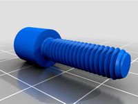
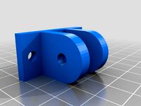
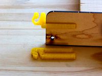
I made 2 versions of the M6 screws, one with Hex heads & one with rounded heads. The hex heads will only work with the connections at the legs. A 3.5mm allen wrench should fit both screws. Thought I might need to put a wrench on the ones attached to the legs, but I really did not need them.
You will need 6 screws for the legs & 2 for the Idler arms and no gluing necessary except for the Cyclops eye. To make sure the screws will fit well, I use an M6 screw & nut to thread on the plastic screws, Idler arms & Drive arm. If you have esun plastic filament, you should have some M6 screws & nuts on there.
This design weighs 5 oz. on my scale with the motor & batteries which is 1.2oz more than my previous remix, so it will run the batteries out quicker. with this extra weight, it probably should be redesigned to use a lipo battery or I might try 2 AAA battery cases wired in series to see if that makes it last longer. Adding another AAA battery case would also add another 1oz to it.
This is motor I ordered, https://www.ebay.com/itm/222940708131 & battery case. https://www.ebay.com/itm/182738715576 .
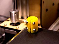
The 1st prints I would do would be the screws & an idler arm to see if your plastic screws will print well on your printer. I print at least 2 of the screws & idler arms at a time to increase the cooling time between print layers of the threading. If you have a print cooler fan that may not be a problem for you.
I printed all the threaded portions of the screws, idler arms & drive arms at .1mm & 20% infill.
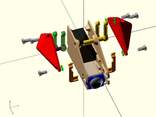
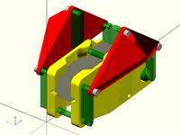
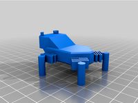
Use the Flippy_Assembly_Rev106.scad or Flippy_Assembly_Rev106.stl to see how the parts go together or the included image maybe enough for you to tell how it all goes together.
Print:
1 - FlippyBody_Mod_Rev119.stl
1 - FlippyLeg_Mod_2x_Rev101.stl
1 - IdleArmShortRound_2x_Rev114.stl
1 - IdleArmLongRound_2x_Rev114.stl
1 - DriveArm_Mod_2x_Rev115.stl
2 - RndBolts_6x_Rev102.stl (You really only need 8 screws)
1 - M6_Washer_6x_Rev1.stl
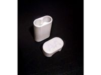
1 - FlippyBody_Mod_EndCap_Rev119.stl
I use esun Pla+ which has a little bit of give to it. If you use regular PLA, you could break the EndCap putting it in place.
If I missed some parts, let me know.
The threaded parts I used are M6 threading and a mating gap of 0.4mm. I print the threaded portions of the parts at .1mm. To modify any of the openscad files that use the threading, you will need to download the threads.scad file from http://dkprojects.net/openscad-threads/ . I put the settings for the threads in the ThreadSettings.scad file, so if you want to adjust the threading it only needs to be done in one place. I used the variable layer height with the Slic3r Prusa edition so I could print the threaded portion at .1mm & the rest of the part at .2mm.
I made 2 versions of the M6 screws, one with Hex heads & one with rounded heads. The hex heads will only work with the connections at the legs. A 3.5mm allen wrench should fit both screws. Thought I might need to put a wrench on the ones attached to the legs, but I really did not need them.
You will need 6 screws for the legs & 2 for the Idler arms and no gluing necessary except for the Cyclops eye. To make sure the screws will fit well, I use an M6 screw & nut to thread on the plastic screws, Idler arms & Drive arm. If you have esun plastic filament, you should have some M6 screws & nuts on there.
This design weighs 5 oz. on my scale with the motor & batteries which is 1.2oz more than my previous remix, so it will run the batteries out quicker. with this extra weight, it probably should be redesigned to use a lipo battery or I might try 2 AAA battery cases wired in series to see if that makes it last longer. Adding another AAA battery case would also add another 1oz to it.
This is motor I ordered, https://www.ebay.com/itm/222940708131 & battery case. https://www.ebay.com/itm/182738715576 .
The 1st prints I would do would be the screws & an idler arm to see if your plastic screws will print well on your printer. I print at least 2 of the screws & idler arms at a time to increase the cooling time between print layers of the threading. If you have a print cooler fan that may not be a problem for you.
I printed all the threaded portions of the screws, idler arms & drive arms at .1mm & 20% infill.
Use the Flippy_Assembly_Rev106.scad or Flippy_Assembly_Rev106.stl to see how the parts go together or the included image maybe enough for you to tell how it all goes together.
Print:
1 - FlippyBody_Mod_Rev119.stl
1 - FlippyLeg_Mod_2x_Rev101.stl
1 - IdleArmShortRound_2x_Rev114.stl
1 - IdleArmLongRound_2x_Rev114.stl
1 - DriveArm_Mod_2x_Rev115.stl
2 - RndBolts_6x_Rev102.stl (You really only need 8 screws)
1 - M6_Washer_6x_Rev1.stl
1 - FlippyBody_Mod_EndCap_Rev119.stl
I use esun Pla+ which has a little bit of give to it. If you use regular PLA, you could break the EndCap putting it in place.
If I missed some parts, let me know.
Similar models
thingiverse
free
Cap Screw - M6 x 20 by eccs19
...1mm thread pitch. thought i'd share in case anyone happens to be looking for one. i've not printed this one out myself.
thingiverse
free
Remix of Flippy the Robot by GeoDave
...nt just one of the sides. if you are using the previous design, the pyramid shaped legs in this design should fit that one also.
thingiverse
free
Traxxas Slash/Rally 4x4 LCG taller battery mounts (1/10) by Meebert
...irely using the stock hardware.
pla will last you a long time but i printed mine in abs because it was loaded and ready to print
thingiverse
free
Heavy Duty Y Axis for Wilson II by lowfat
...16mm and an m3 nut. you can use a 16t idler or a pair of f693zz bearings for the tensioner. the motor mount screws are m3 x 14mm.
thingiverse
free

CYCLOPS 3 Box Case by Flowr
... to secure doors
video : https://www.youtube.com/watch?v=ofzuopzjed8&lc=z235v30y2lrgdzdhk04t1aokgnmljme5psw21obtgzeobk0h00410
thingiverse
free

Door/Draw Handle by A513055
... hear you ask. i recommend 6 gauge screws, but you could get away with 7. the ones in the photo are printed from esun marble pla.
thingiverse
free
Belt Idler for Y Axis - M5 idler size (2020 Mount) by eldor_x
...ler from the original y idler using an m5 thread to screw through it.
you will need 2x m4 8mm screws and 2x m4 t-nut to mount it
thingiverse
free
Threaded Nozzle Storage (M6 threads, E3D compatible)
... a portion as a test if not printing in abs.
needs 2 x m3 8mm screws and t-nuts to mount.
update: added a shorter version (v1.3).
thingiverse
free
AA Battery Case for 2
...n't have the skills to edit .stl. for me, the best looking battery case is the design of https://www.thingiverse.com/scottmi.
thingiverse
free
Super minimalist LCR-T4 case / skeleton / battery clip by Funkster
...inals in first) with the terminals oriented to match the battery clip, then use the longer screws to affix to the back of part a.
Flippy
turbosquid
$9

flippy chain
... free 3d model flippy chain for download as obj, c4d, and fbx on turbosquid: 3d models for games, architecture, videos. (1298182)
turbosquid
$42

MR Flippy the Rock Hopper
... available on turbo squid, the world's leading provider of digital 3d models for visualization, films, television, and games.
thingiverse
free
Flippy the Frog by jbakutis
...flippy the frog by jbakutis
thingiverse
flippy is the world's most comfortable frog.
thingiverse
free
Flippy 2 by chetjohnston
... by chetjohnston
thingiverse
this version is taller, thinner, and has a bottom, so it's a functional cup/vase/pencil holder.
thingiverse
free
Flippy Frog by Scottacus
...whole family.
have something to show your co-workers.
made with 3d printable springs, and prints all in one piece.
positive vibes
thingiverse
free

Flippy 1 by chetjohnston
...it more to enjoy how the surfaces meet.
check the very last picture for a render of what two of these, back-to-back, look like.
thingiverse
free
Flippy the "Robot" by make-a-roni
...ies of each of the files (except the connector).
the body .stl is the left side, mirror it in your slicer to make the right side.
thingiverse
free
Dickie Toys Wild Flippy RC car wheel axle with sprocket by avanhanegem
...r wheel axle with sprocket by avanhanegem
thingiverse
looking for a replacement axel for your dickie rc car?
look no further! ;)
thingiverse
free

FLIPPY - DESK CALENDAR (Stand Only)
...drainer
https://cults3d.com/en/3d-model/home/times-square-2-tabletop-clock
https://cults3d.com/en/3d-model/home/compact-cd-holder
thingiverse
free
King FLIPPY NIPS Shrike V2 by FPVCoco
...ut from the motors. they are motor soft mounts is what i meant.
download everything now! what are you waiting for? it's free.
Geodave
thingiverse
free

Shower Caddy accessory holder by GeoDave
... upside down on out shower caddy. i did this a few months back, but changed the design recently to make it stay in place better.
thingiverse
free
Wood Bracket with Wire Clip by GeoDave
...be either at 0 or 90 degrees to wood bracket. i included the openscad & dxf files if you want to adjust this to other sizes.
thingiverse
free
Gimbal Spinner by GeoDave
...elow 24mm for the inside width clearance distance or below 54mm for the gimbal distance. i will take a look at fixing that soon.
thingiverse
free
Spinning Top with Thumbwheel by GeoDave
... works.
https://youtu.be/fpaissfvmqm
here is the openscad source file for the thumbwheelhttps://www.thingiverse.com/thing:2407027
thingiverse
free
Parametric Shaft Coupler by GeoDave
... - m3x14mm bolts & locknuts for the 5mm to 5mm that is shown printed in yellow petg.
you can also open this in the customizer
thingiverse
free
Thumbwheel for a Jack Screw by GeoDave
...ese parts, i realized this might make a good spinning top. here is a link to that top. https://www.thingiverse.com/thing:2407034
thingiverse
free
Remix of Meade Autostar holder for LXD75/LX90 mount by GeoDave
... added 1mm extra around the holes.
i used 2 - m3x16mm screws with locknuts & printed at 40% infill with esun silver pla pro.
thingiverse
free
Parametric Tapered Spacer by GeoDave
... the larger diameter against the wheels & they did not roll at all. the 2nd & 3rd photo should show what i mean by this.
thingiverse
free
A Very Customizable Funnel by GeoDave
...gs in the openscad script.
i changed the hook_xx variable names to a more appropriate eye_xx names after a friend mentioned this.
thingiverse
free
Parametric Honeycomb containers by GeoDave
...file to varie the size of them based on 8 variables. since making this, i have made a number of containers for various purposes.
Cyclops
turbosquid
$30
Cyclops
...yalty free 3d model cyclops for download as max, fbx, and obj on turbosquid: 3d models for games, architecture, videos. (1523186)
turbosquid
$45

Cyclop
... available on turbo squid, the world's leading provider of digital 3d models for visualization, films, television, and games.
turbosquid
$20

Cyclops
... available on turbo squid, the world's leading provider of digital 3d models for visualization, films, television, and games.
turbosquid
$5

cyclop
... available on turbo squid, the world's leading provider of digital 3d models for visualization, films, television, and games.
turbosquid
$4
Cyclops
...free 3d model cyclops from x-men evolution for download as ma on turbosquid: 3d models for games, architecture, videos. (1168226)
turbosquid
$1
Cyclops
...lops mythological creature monster for download as ma and obj on turbosquid: 3d models for games, architecture, videos. (1606912)
turbosquid
free

The Cyclops
...e cyclops for download as ma, ztl, unitypackage, upk, and fbx on turbosquid: 3d models for games, architecture, videos. (1644884)
3d_export
$39

Cyclops 3D Model
...cyclops 3d model
3dexport
mythology cyclops creature monster
cyclops 3d model gontijo 174 3dexport
turbosquid
$50

CYCLOP RIGGED
...
royalty free 3d model cyclop rigged for download as and fbx on turbosquid: 3d models for games, architecture, videos. (1655303)
turbosquid
$6

cyclops monster
...id
royalty free 3d model cyclops monster for download as obj on turbosquid: 3d models for games, architecture, videos. (1406853)
Bot
turbosquid
$19

Bot
... available on turbo squid, the world's leading provider of digital 3d models for visualization, films, television, and games.
turbosquid
free

Bot
... available on turbo squid, the world's leading provider of digital 3d models for visualization, films, television, and games.
3d_export
$10

scanner bot
...scanner bot
3dexport
cool scanner bot who scans for fixing things...
3d_ocean
$9

Apc Bot
...n bot games toys
an all-purpose-constructo-bot. for cartoon purposes. the model is not rigged. please use vray adv for rendering.
3d_export
$75
Bot 3D Model
...bot 3d model
3dexport
robot bot man kiborg character
bot 3d model evgen 19504 3dexport
turbosquid
free

Eye Bot
...eye bot
turbosquid
free 3d model eye bot for download as fbx on turbosquid: 3d models for games, architecture, videos. (1514059)
turbosquid
$29

Gorill-bot
...bosquid
royalty free 3d model gorill-bot for download as fbx on turbosquid: 3d models for games, architecture, videos. (1239456)
turbosquid
$25

Lamp Bot
...bosquid
royalty free 3d model lamp bot for download as blend on turbosquid: 3d models for games, architecture, videos. (1230121)
turbosquid
$10
Spectre Bot
...osquid
royalty free 3d model spectre bot for download as fbx on turbosquid: 3d models for games, architecture, videos. (1616378)
turbosquid
$8

Ultra Bot
...urbosquid
royalty free 3d model ultra bot for download as ma on turbosquid: 3d models for games, architecture, videos. (1330752)