Thingiverse
Customizable Helix (Helical) Antenna Frame and Winding Template by stylesuxx
by Thingiverse
Last crawled date: 3 years ago
CAUTION: WORK IN PROGRESS
This thing is work in progress. It works good for me, but that does not mean I got every case. I will leave this as work in progress as long as I do not get 10 makes and some feedback.
You can help make this thing better, print it, build it, test it and tell me what you think, where you ran into problems what you liked, what you did not like. Also let me know if the instructions are not clear at any point.
The first time I tested this antenna I was blown away, and I hope I can share this experience with you!
About
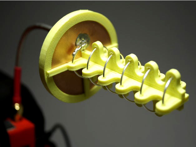
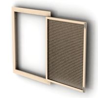
This thing will generate an antenna "frame" and a winding template for your custom helix antenna. Helix antenna are easy to build, polarized, directional antennas with high gain.
The default settings will generate all parts for a right hand polarized, 5.8GHz, 5 turn Helix Antenna with ~10dBi gain, 1mm diameter antenna wire and a beam with of ~50 degrees, to be used for FPV.
More turns means higher gain, but also results in a narrower beam.
The use of a reflector is highly recommended and can be as easy as a copper PCB. either round or square. More information regarding reflectors may be found in this paper
The winding template changes depending on selected polarization. Depending on how you assemble the frame you can use it for the right or left hand polarized antenna.
Use this great calculator to get all the base values for your helix antenna. It will also show you the gain of your antenna and beam width.
The customizers default settings will generate a round reflector frame, you can check out my tool for cuttinig discs from square stock
Tools
For this project you will need the following tools:
Snips
Hobby knife
Soldering Iron & solder
Dremel / Rotary tool
Materials
Other than the 3D printed parts you will need the following materials:
Antenna Wire - I used 1mm diameter silver coated copper wire. Diameter is not that critical, and the material should be single core and you should be able to easily solder to it. * Reflector - I used Bungard double sided copper PCB's. Again, the material and thickness is not that important.
Coaxial Cable - again, does not matter too much, as long as it has an impedance of 50 Ohms. I tried it with the flexible RG58 but also with the semi rigid RG402 which in my opinion is the better choice for on goggle mounting.
Wave Trap - some solderable sheet of metal. I used copper tape and stacked multiple layers, again material should not matter too much, as long as it is not too thick (~0.5mm).
Heat Shrink - I like to color code my antennas, red heat shrink for right hand polarized and blue for left hand polarized.
SMA / RP SMA connector - depending on the receiver you are using you will need an appropriate SMA connector.
Preparation
If you do not use the same materials as I do, or want to use different specs, chances are, that you will need to change one or more parameters in the customizer. Give the customizer some time for rendering. The helix is quite complex to render, so it might take some time (took 30 minutes when I rendered the attached stl's from the default settings.)
Polarization
The polarization is only important for the winding template, all other parts may be used for both, left and right hand polarized antennas. Adjust the polarization value in the General Tab.
Frequency, Turns and Wire Diameter
If you intend to use a different frequency than 5.8GHz or a different number of turns than 5, head over to the calculator and fill in the following values in the General Tab of the customizer:
turns: Amount of turns
D: Inner Diameter of hte antenna
d: Outer Diameter of the antenna wire, adjust this for your printers tolerances
L: The length of the helix
Reflector Material and shape
In the Reflector Cover Tab, adjust reflectorThickness to the thickness of your reflector material. Adjust reflectorDiameter to at least the minimum diameter given by the calculator from above. A circle is recommended but square shape may also be used, if you are to lazy to go for a round shape ;-) Adjust reflectorShape accordingly.
Coaxial Cable
Again, in the Reflector Cover Tab, adjust coaxialDiameter to the thickness of your coaxial cable (with shielding, but without insulation).
Tolerances
Should your parts not fit well enough, check the Tolerances Tab and adjust values accordingly.
Parts
In the General Tab you will also find a dropdown with the parts to render. When rendering all parts it may take some time and the customizer might time out - because of the rather complicated winding template. I recommend reviewing with the Frame Parts selection.
Printing
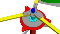
The customizer will generate one file per part and one file with all the parts including winding template and another file with only the frame parts in case you already have your winding template.
Top and bottom frame part may be used for left and right hand polarized antennas, you only need to turn one of the pieces by 180 degrees before sliding it together.
I recommend printing the first layer rather slowly (20mm/s) to give the slopes of the frame a good chance of adhesion to the build plate.
Assembly
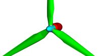
Step 1: Reflector
While the parts are printing you can already start by preparing the reflector. I decided to go with a round reflector with a diameter of 49mm, this is bigger than the recommended minimum diameter from the calculator and allows me to get 6 reflectors out of one PCB, without wasting too much material.
Mark the center of your reflector, also mark the hole for the coax cable (innerDiameter + wireDiameter) / 2. If you are going for a round reflector you can use my disc shaper tool drill a 2mm hole in the center and for the coax. Increase the hole for the coax until it fits snuggly, with the shielding but without the outer insulation.
Lengthen the coax cable, strip the shielding and inner insulation on one side about 5mm, stick it through the hole in your reflector and solder the shielding to the reflector. If you are using a double sided copper PCB as I do here, make sure to solder the shielding to both sides of the PCB.
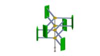
Step 2: Winding the Antenna
Once your winding template has finished you can start winding the antenna. Stick the wire in the little hole on the bottom, and start winding the wire slowly around the template. Keep it as tight as possible. Once you are done, use your snips to cut away the bottom part and turn the antenna off the template. The antenna windings might compress back a bit so gently pull them apart.
Step 3: Antenna support
Assemble top and bottom part of the antenna support, make sure that all the holes are clear and you have enough space for the wire. Start turning the antenna through the holes, until you reach the bottom.
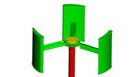
Step 4: Enclosure
slide the reflector into the groves of the antenna support, add the ring with the slits from the top and the cover from the back. At this point you can glue ring and cover shut.
Step 5: Soldering Antenna
Solder the Antenna wire to the core of the coaxial cable. Make sure that the first 1/4 loop is at a height of 2.5mm from the reflector to the center of the wire (Feed point height).
Cut the center pin of the coax to height.
Step 6: Wavetrap
Cut the wavetrap to size (6.5mm x 3.2mm for 5.8GHz or Length in cm = 3720 / f in MHz, Width in cm = 1860/f in MHz) and solder it to the the center of the first 1/4 turn of your antenna.
Step 6: SMA / RP SMA
Strip the shielding and inner insulation from the coax cable on the other side about 3mm. Solder the center pin to the inner core of your coax. If you want to use heat shrink put it on now. Plug in the coax with the center pin soldered to the plug. Solder the shielding to the plug and use hot air or your lighter to shrink the heat shrink.
Step 7: Cleanup
Should the wire of the antenna be longer than the top hole, simply snip it. As last check, make sure you did not short out the antenna anywhere, therefore simply check for continuity on the SMA Connector.
That is it, you now have build your own helical antenna, now got out, test it and let me know what you think.
Results
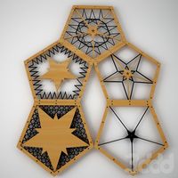
I first build the square version you can see in the images. I went out and tried it out and was blown away by the results, 750m with a transmitter on 25mW and a clover leaf antenna.
Massive penetration, having some trees in line of sight was no problem, also the image was crystal clear almost all the time.
Shout outs
Massive shout out to IBCrazy from RCGroups who came up with the wave trap and made the helix antenna popular for FPV.
References
RCGroups' IBCracy helical Antenna and Wavetrap Tutorial
This thing is work in progress. It works good for me, but that does not mean I got every case. I will leave this as work in progress as long as I do not get 10 makes and some feedback.
You can help make this thing better, print it, build it, test it and tell me what you think, where you ran into problems what you liked, what you did not like. Also let me know if the instructions are not clear at any point.
The first time I tested this antenna I was blown away, and I hope I can share this experience with you!
About
This thing will generate an antenna "frame" and a winding template for your custom helix antenna. Helix antenna are easy to build, polarized, directional antennas with high gain.
The default settings will generate all parts for a right hand polarized, 5.8GHz, 5 turn Helix Antenna with ~10dBi gain, 1mm diameter antenna wire and a beam with of ~50 degrees, to be used for FPV.
More turns means higher gain, but also results in a narrower beam.
The use of a reflector is highly recommended and can be as easy as a copper PCB. either round or square. More information regarding reflectors may be found in this paper
The winding template changes depending on selected polarization. Depending on how you assemble the frame you can use it for the right or left hand polarized antenna.
Use this great calculator to get all the base values for your helix antenna. It will also show you the gain of your antenna and beam width.
The customizers default settings will generate a round reflector frame, you can check out my tool for cuttinig discs from square stock
Tools
For this project you will need the following tools:
Snips
Hobby knife
Soldering Iron & solder
Dremel / Rotary tool
Materials
Other than the 3D printed parts you will need the following materials:
Antenna Wire - I used 1mm diameter silver coated copper wire. Diameter is not that critical, and the material should be single core and you should be able to easily solder to it. * Reflector - I used Bungard double sided copper PCB's. Again, the material and thickness is not that important.
Coaxial Cable - again, does not matter too much, as long as it has an impedance of 50 Ohms. I tried it with the flexible RG58 but also with the semi rigid RG402 which in my opinion is the better choice for on goggle mounting.
Wave Trap - some solderable sheet of metal. I used copper tape and stacked multiple layers, again material should not matter too much, as long as it is not too thick (~0.5mm).
Heat Shrink - I like to color code my antennas, red heat shrink for right hand polarized and blue for left hand polarized.
SMA / RP SMA connector - depending on the receiver you are using you will need an appropriate SMA connector.
Preparation
If you do not use the same materials as I do, or want to use different specs, chances are, that you will need to change one or more parameters in the customizer. Give the customizer some time for rendering. The helix is quite complex to render, so it might take some time (took 30 minutes when I rendered the attached stl's from the default settings.)
Polarization
The polarization is only important for the winding template, all other parts may be used for both, left and right hand polarized antennas. Adjust the polarization value in the General Tab.
Frequency, Turns and Wire Diameter
If you intend to use a different frequency than 5.8GHz or a different number of turns than 5, head over to the calculator and fill in the following values in the General Tab of the customizer:
turns: Amount of turns
D: Inner Diameter of hte antenna
d: Outer Diameter of the antenna wire, adjust this for your printers tolerances
L: The length of the helix
Reflector Material and shape
In the Reflector Cover Tab, adjust reflectorThickness to the thickness of your reflector material. Adjust reflectorDiameter to at least the minimum diameter given by the calculator from above. A circle is recommended but square shape may also be used, if you are to lazy to go for a round shape ;-) Adjust reflectorShape accordingly.
Coaxial Cable
Again, in the Reflector Cover Tab, adjust coaxialDiameter to the thickness of your coaxial cable (with shielding, but without insulation).
Tolerances
Should your parts not fit well enough, check the Tolerances Tab and adjust values accordingly.
Parts
In the General Tab you will also find a dropdown with the parts to render. When rendering all parts it may take some time and the customizer might time out - because of the rather complicated winding template. I recommend reviewing with the Frame Parts selection.
Printing
The customizer will generate one file per part and one file with all the parts including winding template and another file with only the frame parts in case you already have your winding template.
Top and bottom frame part may be used for left and right hand polarized antennas, you only need to turn one of the pieces by 180 degrees before sliding it together.
I recommend printing the first layer rather slowly (20mm/s) to give the slopes of the frame a good chance of adhesion to the build plate.
Assembly
Step 1: Reflector
While the parts are printing you can already start by preparing the reflector. I decided to go with a round reflector with a diameter of 49mm, this is bigger than the recommended minimum diameter from the calculator and allows me to get 6 reflectors out of one PCB, without wasting too much material.
Mark the center of your reflector, also mark the hole for the coax cable (innerDiameter + wireDiameter) / 2. If you are going for a round reflector you can use my disc shaper tool drill a 2mm hole in the center and for the coax. Increase the hole for the coax until it fits snuggly, with the shielding but without the outer insulation.
Lengthen the coax cable, strip the shielding and inner insulation on one side about 5mm, stick it through the hole in your reflector and solder the shielding to the reflector. If you are using a double sided copper PCB as I do here, make sure to solder the shielding to both sides of the PCB.
Step 2: Winding the Antenna
Once your winding template has finished you can start winding the antenna. Stick the wire in the little hole on the bottom, and start winding the wire slowly around the template. Keep it as tight as possible. Once you are done, use your snips to cut away the bottom part and turn the antenna off the template. The antenna windings might compress back a bit so gently pull them apart.
Step 3: Antenna support
Assemble top and bottom part of the antenna support, make sure that all the holes are clear and you have enough space for the wire. Start turning the antenna through the holes, until you reach the bottom.
Step 4: Enclosure
slide the reflector into the groves of the antenna support, add the ring with the slits from the top and the cover from the back. At this point you can glue ring and cover shut.
Step 5: Soldering Antenna
Solder the Antenna wire to the core of the coaxial cable. Make sure that the first 1/4 loop is at a height of 2.5mm from the reflector to the center of the wire (Feed point height).
Cut the center pin of the coax to height.
Step 6: Wavetrap
Cut the wavetrap to size (6.5mm x 3.2mm for 5.8GHz or Length in cm = 3720 / f in MHz, Width in cm = 1860/f in MHz) and solder it to the the center of the first 1/4 turn of your antenna.
Step 6: SMA / RP SMA
Strip the shielding and inner insulation from the coax cable on the other side about 3mm. Solder the center pin to the inner core of your coax. If you want to use heat shrink put it on now. Plug in the coax with the center pin soldered to the plug. Solder the shielding to the plug and use hot air or your lighter to shrink the heat shrink.
Step 7: Cleanup
Should the wire of the antenna be longer than the top hole, simply snip it. As last check, make sure you did not short out the antenna anywhere, therefore simply check for continuity on the SMA Connector.
That is it, you now have build your own helical antenna, now got out, test it and let me know what you think.
Results
I first build the square version you can see in the images. I went out and tried it out and was blown away by the results, 750m with a transmitter on 25mW and a clover leaf antenna.
Massive penetration, having some trees in line of sight was no problem, also the image was crystal clear almost all the time.
Shout outs
Massive shout out to IBCrazy from RCGroups who came up with the wave trap and made the helix antenna popular for FPV.
References
RCGroups' IBCracy helical Antenna and Wavetrap Tutorial
Similar models
thingiverse
free

7 turn Helical FPV antenna (5.8 GHz) by Dvogonen
...length. this section of the wire should be located 2 mm from the surface of the reflector (thanks to dave855 for the information)
thingiverse
free

5 turn Helical FPV antenna (5.8 GHz) by Dvogonen
...length. this section of the wire should be located 2 mm from the surface of the reflector (thanks to dave855 for the information)
thingiverse
free

Boscam Transmitter Case with deported antenna by rboutrois
... just have to desolder the connector from your emitter, screw it in the case hole and solder it to the emitter with a coax cable.
thingiverse
free

Splice Jig by EelAudio
...cold wires.
put the jig into position and then solder the shield wire over them.
seal up with heat shrink (glue filled preferred)
thingiverse
free

5.8 ghz helical antenna template (for FPV) by xack
...he angle and turn the helix down the template.
according to the calculater the reflector hast to be at least 32 mm in diameter.
thingiverse
free

1.7 GHz Helical Feed (HRPT) by derekcz
...the helix is lhcp, the polarization is inverted when used with a dish reflector thus once assembled it results in a rhcp antenna.
thingiverse
free

S helical 5.8ghz by runaway380
...this is a 5.8ghz antenna for the rg402 coax similar to a helical antenna. this should be printed in...
thingiverse
free

403MHz Helix Antenna Dolly for RadioSonde Tracker by eben80
...0mm.
you can superglue into place once the wire is wound and trim the print on the side where the feed wire needs to be soldered.
thingiverse
free

Coaxial Cable Wall Grommet
...n, the hole diameter should be 9mm.
any hams out there, feel free to leave your ham radio call sign in the comments section.
73!
thingiverse
free

8 to 12 GHz Horn antenna with Coax-Waveguide transducer by kodera2t
...connector attachment. (centre dielectric of sma must be elongated with covered by metal, and it should be inserted in the hole..)
Stylesuxx
thingiverse
free

CCCamp15 Keychain by stylesuxx
...cccamp15 keychain by stylesuxx
thingiverse
chaos communication camp 2015 logo as a keychain.
thingiverse
free

Acrobrat - Front Bumpers by stylesuxx
...acrobrat - front bumpers by stylesuxx
thingiverse
simple front bumpers for ummagawd's acrobrat frame.
thingiverse
free

Customizer bug? by stylesuxx
...izer?
calculated values not properly applied.
preview is rendering ok as image, but costomizer does not show any of the cubes,...
thingiverse
free

Abalone replacement Ball by stylesuxx
...abalone replacement ball by stylesuxx
thingiverse
print two (or n*2) of those, glue them together and sand them down.
thingiverse
free

Tevo Tarantula Filament Runout Sensor Enclosure of stylesuxx without screws by nitro974
... enclosure of stylesuxx without screws by nitro974
thingiverse
screwless version of the very good filament sensor from stylesuxx
thingiverse
free

Customizable Pinning Tray by stylesuxx
... the slots, roundness of the tray and size of the slot for the cylinder.
the attached stl is a rendering of the default settings.
thingiverse
free

Customizable Atomizer Stand by stylesuxx
... print with just one row and one column to make sure your atomizers fit. after that you can print the stand in your desired size.
thingiverse
free

Acrobrat - Front Cover (customizable) by stylesuxx
...d. you can customize the cam hole diameter and position.
the attached stl is an export of the default settings of the customizer.
thingiverse
free

Customizable Cylindrical Box by stylesuxx
...games.
the customizer will generate three stl's for you. one of the container, one of the lid and one with both, to show off.
thingiverse
free

Buzzer Mounting Bracket by stylesuxx
...te a bracket fitting the following components:
frame
buzzer
for good measure i would recommend to glue the buzzer to the bracket.
Helical
3d_export
$5

helical gear
...helical gear
3dexport
helical gear
3d_export
$5
Helical Gear
...l contact ratio which can improve vibration and noise. badly designed helical gears can be noisier than well designed spur gears.
turbosquid
$5
Helical Gear
...squid
royalty free 3d model helical gear for download as stl on turbosquid: 3d models for games, architecture, videos. (1502723)
turbosquid
$4

helical gears
...id
royalty free 3d model helical gears for download as blend on turbosquid: 3d models for games, architecture, videos. (1423917)
turbosquid
$40

Helical Stairs
...el helical stairs for download as 3ds, max, ige, obj, and fbx on turbosquid: 3d models for games, architecture, videos. (1422987)
turbosquid
$32

armchair-Helical
... available on turbo squid, the world's leading provider of digital 3d models for visualization, films, television, and games.
turbosquid
$20

helical gear
... available on turbo squid, the world's leading provider of digital 3d models for visualization, films, television, and games.
turbosquid
$10

helical gear
...cal gear for download as max, unitypackage, 3ds, fbx, and obj on turbosquid: 3d models for games, architecture, videos. (1667275)
turbosquid
$4

Helical gear
... gear for download as sldpr, 3dm, 3ds, fbx, ige, obj, and stl on turbosquid: 3d models for games, architecture, videos. (1530622)
3d_export
$50

HELICAL BEVEL GEAR
...lel and perpendicular. in parallel-axis helical gears the two opposite-hand gears provide quiet operation and high load capacity.
Helix
design_connected
$9
Helix
...helix
designconnected
brent comber helix computer generated 3d model. designed by comber, brent.
turbosquid
free

Helix
...helix
turbosquid
free 3d model helix for download as fbx on turbosquid: 3d models for games, architecture, videos. (1490983)
3d_ocean
$20

Helix SPXL12
...helix spxl12
3docean
all and helix included of rendered scene setups spxl12 subwoofer the vray with
subwoofer helix spxl12
turbosquid
$69

Helix
... available on turbo squid, the world's leading provider of digital 3d models for visualization, films, television, and games.
3d_export
$5

Helix 3D Model
...helix 3d model
3dexport
helix
helix 3d model jopaas 82470 3dexport
turbosquid
$62

helix bridge
...squid
royalty free 3d model helix bridge for download as skp on turbosquid: 3d models for games, architecture, videos. (1345787)
turbosquid
$10
Helix Table
...osquid
royalty free 3d model helix table for download as obj on turbosquid: 3d models for games, architecture, videos. (1174648)
turbosquid
$5

Helix Lamp
...ty free 3d model helix lamp for download as c4d, obj, and fbx on turbosquid: 3d models for games, architecture, videos. (1631703)
turbosquid
$333

Townscape: HELIX
... available on turbo squid, the world's leading provider of digital 3d models for visualization, films, television, and games.
turbosquid
$200

DNA Helix
... available on turbo squid, the world's leading provider of digital 3d models for visualization, films, television, and games.
Antenna
archibase_planet
free
Antenna
...chibase planet
antenna aerial television antenna
antenna kathrein n090913 - 3d model (*.gsm+*.3ds) for exterior 3d visualization.
archibase_planet
free
Antenna
...antenna
archibase planet
satellite antenna
antenna 1 - 3d model (*.gsm+*.3ds) for exterior 3d visualization.
archibase_planet
free
Antenna
...antenna
archibase planet
equipment satellite antenna
antenna 2 - 3d model (*.gsm+*.3ds) for exterior 3d visualization.
archibase_planet
free
Antenna
...ntenna
archibase planet
satellite antenna equipment dish aerial
antenna 3 - 3d model (*.gsm+*.3ds) for exterior 3d visualization.
archibase_planet
free
Antenna
...antenna
archibase planet
satellite antenna dish dish aerial
antenna 4 - 3d model (*.gsm+*.3ds) for exterior 3d visualization.
archibase_planet
free
Antenna
...e planet
antenna dish dish aerial
antenna c-band satellite s180-g n210612 - 3d model (*.gsm+*.3ds) for exterior 3d visualization.
3d_export
$5

car antenna
...car antenna
3dexport
car antenna, antenna, car gadgets
turbosquid
$1

antenna
...rbosquid
royalty free 3d model antenna for download as blend on turbosquid: 3d models for games, architecture, videos. (1655786)
3d_export
free

Station with antenna
...station with antenna
3dexport
station with antenna
turbosquid
$5

Antenna
...id
royalty free 3d model antenna for download as max and fbx on turbosquid: 3d models for games, architecture, videos. (1381532)
Template
turbosquid
$70

Coffee templates
...d
royalty free 3d model coffee templates for download as stl on turbosquid: 3d models for games, architecture, videos. (1393377)
turbosquid
$30

Flightcase Template
...royalty free 3d model flightcase template for download as fbx on turbosquid: 3d models for games, architecture, videos. (1671830)
turbosquid
$4

monster template
... available on turbo squid, the world's leading provider of digital 3d models for visualization, films, television, and games.
turbosquid
$3

BMX template
... available on turbo squid, the world's leading provider of digital 3d models for visualization, films, television, and games.
turbosquid
free

template v3
... available on turbo squid, the world's leading provider of digital 3d models for visualization, films, television, and games.
3d_ocean
$9

Animated Magazine Template
...y variables to suit whichever project you’re working on . main features: multiple templates based on page count (2 – 6 ...
turbosquid
$10

Human Head Template
...royalty free 3d model human head template for download as obj on turbosquid: 3d models for games, architecture, videos. (1297440)
turbosquid
$59

template muscle man
... available on turbo squid, the world's leading provider of digital 3d models for visualization, films, television, and games.
turbosquid
$10

LittleBody Woman Template
... available on turbo squid, the world's leading provider of digital 3d models for visualization, films, television, and games.
turbosquid
$10

Template For Steel Texture
... available on turbo squid, the world's leading provider of digital 3d models for visualization, films, television, and games.
Winding
design_connected
$4

Wind
...wind
designconnected
emmemobili wind dining tables computer generated 3d model. designed by chiara vaghi.
3d_ocean
$4

Wind Turbine
...n
and render setup turbine wind
wind turbine, modeled with cinema4d r13 , render setup and textured, custom logo for wind turbine
3d_export
$40
wind turbine
...wind turbine
3dexport
wind turbine
3d_export
$40

wind turbine
...wind turbine
3dexport
wind turbine
3d_export
$40
wind turbine
...wind turbine
3dexport
wind turbine
3d_export
$40
wind turbine
...wind turbine
3dexport
wind turbine
3d_export
$40
wind turbine
...wind turbine
3dexport
wind turbine
3d_export
$40
wind turbine
...wind turbine
3dexport
wind turbine
3d_export
$40

wind turbine
...wind turbine
3dexport
wind turbine
3d_export
$40

wind turbine
...wind turbine
3dexport
wind turbine
Customizable
3d_export
$10
customizable sd port
...customizable sd port
3dexport
customizable sd port
turbosquid
$99

Customizable character
...alty free 3d model customizable character for download as max on turbosquid: 3d models for games, architecture, videos. (1152525)
turbosquid
$1

Customizable Mug
... available on turbo squid, the world's leading provider of digital 3d models for visualization, films, television, and games.
turbosquid
$1
Customizable Spider Mech
... free 3d model customizable spider mech for download as blend on turbosquid: 3d models for games, architecture, videos. (1462055)
turbosquid
$20

Customizable Egyptian Pillar
...zable egyptian pillar for download as ma, obj, fbx, and blend on turbosquid: 3d models for games, architecture, videos. (1307376)
turbosquid
$75

Fully Customizable Hospital
... available on turbo squid, the world's leading provider of digital 3d models for visualization, films, television, and games.
turbosquid
$20

Customizable Caste Pieces
... available on turbo squid, the world's leading provider of digital 3d models for visualization, films, television, and games.
turbosquid
$15
Customizable Tea Cup
... available on turbo squid, the world's leading provider of digital 3d models for visualization, films, television, and games.
turbosquid
free

Water Bottle(Customizeable)
... available on turbo squid, the world's leading provider of digital 3d models for visualization, films, television, and games.
3d_export
$49

Book customizable 3D Model
...3dexport
book booshelf novel teach library learn read pages cover fairy tales
book customizable 3d model guitargoa 74240 3dexport
Frame
archibase_planet
free
Frame
...frame
archibase planet
frame photo frame
frame n190813 - 3d model (*.gsm+*.3ds) for interior 3d visualization.
archibase_planet
free

Frame
...frame
archibase planet
frame photo frame
frame n071113 - 3d model (*.gsm+*.3ds) for interior 3d visualization.
3ddd
$1

Frame
...frame
3ddd
frame
3ddd
free
Frame
...frame
3ddd
frame
archibase_planet
free

Frame
...frame
archibase planet
frame mirror frame ornament
frame n260113 - 3d model (*.gsm+*.3ds) for interior 3d visualization.
archibase_planet
free

Frame
...frame
archibase planet
frame photo frame
frame photo n190813 - 3d model (*.gsm+*.3ds) for interior 3d visualization.
archibase_planet
free
Frame
...frame
archibase planet
frame window window frame
frame 1 - 3d model (*.gsm+*.3ds) for interior 3d visualization.
archibase_planet
free
Frame
...frame
archibase planet
frame window frame window
frame 3 - 3d model (*.gsm+*.3ds) for interior 3d visualization.
archibase_planet
free
Frame
...frame
archibase planet
frame wall frame decoration
frame 1 - 3d model (*.gsm+*.3ds) for interior 3d visualization.
archibase_planet
free
Frame
...frame
archibase planet
frame window window frame
frame 2 - 3d model (*.gsm+*.3ds) for interior 3d visualization.