Thingiverse

Customizable Fishbone Lamella Gas Seperation Grid for Electrolysis by mechadense
by Thingiverse
Last crawled date: 3 years ago
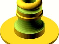
This is a halve grid for gas separation in an electrolysis apparatus.
When two (mirrored versions) of these are put together back on back the lamellas form herringbone shapes. This disallows the gasses to pass from one side to the other and mix.
.
In a concrete application a gas separation wall must be extended upwards and the fluid level must be always kept above the grid.
Standalone this thing is incomplete. An electrolysis chamber capable of gas separation is needed in conjunction. It might be a good idea to design the gas splitter top as one piece print with mainly diagonal surfaces to archive maximum gas tightness.
.
pros & cons:
no separation membranes (filterpaper / 0.1mm mesh fine lye resistant textiles) needed
if separation membranes are used nonetheless they are mechanically stabilized by the grid
more distance between the plates (resistive losses) more electrolyte needed
less water cross section between plates
Some data randomly found on the net (no guarantee of correctness):
1.5mm to (2.0mm) for bubble-flow needed
keep current below 85mA/cm^2 of plate area
try to archive 2V voltage drop per plate
=> six plates in series are useful:
connect only the outermost two for 12V operation and
connect only the second from outermost for for 9V operation
.
One side can be made to have no slide-in border so that one can look in when a transparent window is glued onto the chamber.
.
problem:
ABS is rather not lye resistant
PET is not lye resistant at all
PLA: ??
nylon: ??
PP & HDPE: is good
cast polyurethane: ??
Similar models
grabcad
free

Membrane Cell
...membrane cell
grabcad
membrane cell electrolysis catalyst layer collector cooling channel diffusion layer gas channel
thingiverse
free

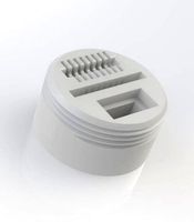
CX500 carb mounts by robmink
... o-rings to seal the connection between the head and these parts. only print in nylon, as it has gas and temp resistance needed.
grabcad
free

Diaphragm Compressor
...adequate chemical properties and sufficient temperature resistance.
a diaphragm compressor is the same as a membrane compressor.
grabcad
free

Membrane gas separator
...membrane gas separator
grabcad
membrane gas separator
grabcad
free

Gas Separations Membrane
...gas separations membrane
grabcad
gas separations membrane
cg_trader
$10

Diaphragm compressor
...d are sealed without leakage. mechanical mechanics machinery machine equipment compressor diaphragm industrial industrial machine
grabcad
free

Visit Card Box
...e opening the upper or lower cover.
also this sheet metal is needed for holding closed the complete box, by means of both clips.
thingiverse
free

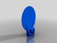
Telrad Riser by csspar
...ped out on one side.
i found it easier to put the risers on the telrad first, then attach to the mounting plate on the telescope.
cg_trader
$5

Yamaha R1 mirror plates | 3D
...les when the mirrors are removed.
there are two versions, one that must respect side and another that can be used on both sides.
grabcad
free

Clutch
...when in operation, but nowadays there are torque-limited couplings that can slip or disconnect when the torque limit is exceeded.
Electrolysis
turbosquid
$10

electrolysis
... available on turbo squid, the world's leading provider of digital 3d models for visualization, films, television, and games.
3d_export
$100

electrolysis bath
...electrolysis bath
3dexport
cg_studio
$50

Electrolysis3d model
...
cgstudio
electronics electrolysis
.max - electrolysis 3d model, royalty free license available, instant download after purchase.
thingiverse
free

Electrolysis Chamber by hockenmaier
...drogen from oxygen in water. try it as a science experiment, to make hydrogen for balloons and airships, or just to set on fire!
thingiverse
free

Test tube holder for electrolysis by poytureg
... fold a wire and put it in the test tube to make electrolysis. i put these in a bucket full of water-sodium bicarbonate solution.
thingiverse
free

Electrolysis gas selective house by poytureg
...ubes on the top, and folded aluminium sheet (a ribbon) between the nails. this should not make any rust, and should be effective.
thingiverse
free

Electrolysis Bucket by poytureg
...t because i can't find ones to buy or to print. i will add gas tube-collectors to have more room or to redirect the gas flow.
thingiverse
free

Contact Holder for Electrolysis
... the contacts very close together so that you do not need as much voltage to have a lot of current pass through the water.
enjoy!
thingiverse
free

Electrolysis HHO Cell Lid (mason Jar 77mm dia.) by Orlando_Luscombe
...ated gasses (hydrogen, oxygen, chlorine ect.) although the electode inset holes should be sealed if the gass retention is needed.
thingiverse
free

Coca-Cola Electrolysis by fawks03
...ces and by applying a voltage hydrogen will form at the negative side.
don't use aluminium foil! (oh- + al+ --> alo) <
Mechadense
thingiverse
free

Bee ... by mechadense
...bee ... by mechadense
thingiverse
print request at
linuxwochen 2015 vienna austriahttp://www.linuxwochen.at/wien/
thingiverse
free

Product by mechadense
...product by mechadense
thingiverse
just a prop. convert your phone to a fake atomically precise personal fabricator.
thingiverse
free
Water Hose Connector by mechadense
...water hose connector by mechadense
thingiverse
compatible with the gardener(tm) system.
thingiverse
free
Gyroid Cylinder by mechadense
...iverse
made with minisagecadashttp://www.thingiverse.com/thing:40210
command: intersection2(cylinderc(30,60),gyroid_left(3,25))
thingiverse
free

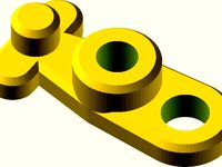
Sheet Pin by mechadense
...nse
thingiverse
a pin & clamping ring combo to clamp thin plates together.
e.g. usable as connectors for scissor mechanisms.
thingiverse
free
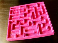
Maze 10x10 - simple by mechadense
...maze 10x10 - simple by mechadense
thingiverse
singly connected. every pair of points can be used as start and goal.
thingiverse
free
Nail-to-Tentpeg Converter by mechadense
...nail-to-tentpeg converter by mechadense
thingiverse
make tentpegs from nails with this little heads.
customize to your needs.
thingiverse
free
Simplistic Symmetric Die by mechadense
...simplistic symmetric die by mechadense
thingiverse
for gaming afk.
you can support me by ordering there:shapeways entry
thingiverse
free
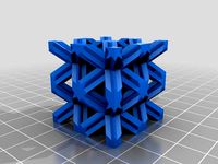
111 spaceframe demo by mechadense
...111 spaceframe demo by mechadense
thingiverse
if you want to know how a 111 space-frame looks like here it is.
thingiverse
free
Toy Propeller Fin by mechadense
...toy propeller fin by mechadense
thingiverse
fin for my old two blade propeller thing:http://www.thingiverse.com/thing:8178
Fishbone
3ddd
free

Стол Moroso - Fishbone
... fishbone
стол moroso - fishbone, tavolino
габариты - №37 - 540х340х450 (h)
№38 - 680х540х400 (h)
№41 - 1080х680х350 (h)
3ddd
$1

декоративный набор flamant
...case flamant_barbara black 41 cm flamant_picture frame mila grey fishbone 10x15 flamant_picture frame mila grey fishbone 13x18 flamant_game ev...
3d_export
$15

Fish Bone 3D Model
...fish bone 3d model 3dexport fish bone fishbone sea ocean ishikawa diagram herringbone cause and effect fishikawa...
thingiverse
free

Fishbone by OZAR
...fishbone by ozar
thingiverse
now you can enjoy the fishbone!
thingiverse
free

Fishbones Ring by ZekeAsakura
...fishbones ring by zekeasakura
thingiverse
fishbones ring
⌀20mm
thingiverse
free

fishbone by carmelo2701
...fishbone by carmelo2701
thingiverse
fish
thingiverse
free

Fishbone Keychain by zumili
...fishbone keychain by zumili
thingiverse
this thing is a simple but smooth keychain shaped as a fishbone.
thingiverse
free

Fishbone by Alajaz
...fishbone by alajaz
thingiverse
simple 3d printing model
3d_sky
free

Table Moroso - Fishbone
...3dsky
moroso
table moroso - fishbone, tavolino dimensions - № 37 - 540h340h450 (h) № 38 - 680h540h400 (h) № 41 - 1080h680h350 (h)
thingiverse
free

Fishbone Meeple / Token by MementoMori
...fishbone meeple / token by mementomori
thingiverse
a fishbone meeple/token for vicious fishes or any other boardgame.
Lamella
3ddd
$1

801047 LAMELLA Lightstar
...star
3ddd
lamella , lightstar
801047 lamella lightstarhttp://www.lightstar.ru/
3ddd
$1

801616 LAMELLA Lightstar
...star
3ddd
lamella , lightstar
801616 lamella lightstarhttp://www.lightstar.ru/
3ddd
$1

801627 LAMELLA Lightstar
...star
3ddd
lamella , lightstar
801627 lamella lightstarhttp://www.lightstar.ru/
3ddd
$1

801617 LAMELLA Lightstar
...star
3ddd
lamella , lightstar
801617 lamella lightstarhttp://www.lightstar.ru/
3ddd
$1

801046 LAMELLA Lightstar
...star
3ddd
lamella , lightstar
801046 lamella lightstarhttp://www.lightstar.ru/
3ddd
free

MOLTO LUCE Lamella Fragola
...e
новая модель люстры от итальянской фабрики molto lucehttp://www.moltoluce.com/index.cfm?seite=lamella&sprache;=en
3ddd
$1

MOLTO LUCE Lamella
...molto luce lamella
3ddd
molto luce
люстры от итальянской фабрики molto luce
turbosquid
$30

Facade panels / lamellas - parametric v2019
...cade panels / lamellas - parametric v2019 for download as rvt on turbosquid: 3d models for games, architecture, videos. (1438344)
3d_export
$10

rocking chair
...and garden. for cnc machine. assembly on pins ø8 lamella 18x40mm and...
3ddd
$1

birch chair
...birch chair, design by konstantin grcic (2014) backrest: birch lamella natural lacquered, painted asphalt, white or red. legs: solid...
Seperation
turbosquid
$10

Seperator
...rbosquid
royalty free 3d model seperator for download as max on turbosquid: 3d models for games, architecture, videos. (1223976)
3ddd
$1

Ray seperator
...eperatör frame
golden or black wood
for seperate big places with beautiful objects
dimentions : 240x120 cm
.
.
designed by aymu .
turbosquid
$5

SEPERATOR & DECOR
... available on turbo squid, the world's leading provider of digital 3d models for visualization, films, television, and games.
turbosquid
$300

Stomach seperable parts
...y free 3d model stomach seperable parts for download as blend on turbosquid: 3d models for games, architecture, videos. (1338515)
3d_export
$5

surprising seperator model
...
the surprising seperator can be an impressive element for your projects.<br>fast rendering, low polygon, realistic image.
3d_export
$5

3d classic seperator
...d classic seperator can be an impressive element for your projects. easy to use, realistic image, low polygon, quality materials.
turbosquid
$300

Foot Seperated Bones With Label
...d model foot seperated bones with label for download as blend on turbosquid: 3d models for games, architecture, videos. (1481344)
turbosquid
$4

Seperate letters keyboard model
... available on turbo squid, the world's leading provider of digital 3d models for visualization, films, television, and games.
3d_export
$39

liquid seperator
...rtice: 191854 attention! - need exteriors scenes + game ready terrain, house, buildings, and props? - check rest of our products.
3d_export
$39

liquid seperator 2
...rtice: 108132 attention! - need exteriors scenes + game ready terrain, house, buildings, and props? - check rest of our products.
Grid
archibase_planet
free

Grid
...grid
archibase planet
grid grating grate
grid n050907 - 3d model (*.gsm+*.3ds) for interior 3d visualization.
archibase_planet
free

Grid
...grid
archibase planet
grid netting guard
grid n270214 - 3d model (*.gsm+*.3ds+*.max) for exterior 3d visualization.
archibase_planet
free

Grid
...grid
archibase planet
grid grating grate
grid modular n020114 - 3d model (*.gsm+*.3ds+*.max) for interior 3d visualization.
archibase_planet
free

Grid
...grid
archibase planet
grating grate lattic
grid n080311 - 3d model (*.gsm+*.3ds) for interior 3d visualization.
turbosquid
$10

grid
...oyalty free 3d model grid for download as blend, obj, and fbx on turbosquid: 3d models for games, architecture, videos. (1701808)
turbosquid
$9

Grid
... available on turbo squid, the world's leading provider of digital 3d models for visualization, films, television, and games.
3d_export
$5

Bust manwoman grid
...bust manwoman grid
3dexport
bust manwoman grid
3d_export
$5

Manwoman join grid
...manwoman join grid
3dexport
man_woman join grid
3d_export
$5

Middle finger grid
...middle finger grid
3dexport
middle finger grid
3d_export
$5

Head mickey grid
...head mickey grid
3dexport
head mickey grid
Customizable
3d_export
$10
customizable sd port
...customizable sd port
3dexport
customizable sd port
turbosquid
$99
Customizable character
...alty free 3d model customizable character for download as max on turbosquid: 3d models for games, architecture, videos. (1152525)
turbosquid
$1
Customizable Mug
... available on turbo squid, the world's leading provider of digital 3d models for visualization, films, television, and games.
turbosquid
$1
Customizable Spider Mech
... free 3d model customizable spider mech for download as blend on turbosquid: 3d models for games, architecture, videos. (1462055)
turbosquid
$20
Customizable Egyptian Pillar
...zable egyptian pillar for download as ma, obj, fbx, and blend on turbosquid: 3d models for games, architecture, videos. (1307376)
turbosquid
$75
Fully Customizable Hospital
... available on turbo squid, the world's leading provider of digital 3d models for visualization, films, television, and games.
turbosquid
$20

Customizable Caste Pieces
... available on turbo squid, the world's leading provider of digital 3d models for visualization, films, television, and games.
turbosquid
$15
Customizable Tea Cup
... available on turbo squid, the world's leading provider of digital 3d models for visualization, films, television, and games.
turbosquid
free
Water Bottle(Customizeable)
... available on turbo squid, the world's leading provider of digital 3d models for visualization, films, television, and games.
3d_export
$49
Book customizable 3D Model
...3dexport
book booshelf novel teach library learn read pages cover fairy tales
book customizable 3d model guitargoa 74240 3dexport
Gas
archibase_planet
free
Gas
...gas
archibase planet
kitchen range gas stove cooker
gas - 3d model (*.gsm+*.3ds) for interior 3d visualization.
archibase_planet
free
Gas-stove
...e
archibase planet
gas-stove gas cooker kitchen-range gas stove
gas-stove - 3d model (*.gsm+*.3ds) for interior 3d visualization.
archibase_planet
free
Gas stove
...ase planet
gas stove kitchen-range gas-stove gas cooker
gas stove n280711 - 3d model (*.gsm+*.3ds) for interior 3d visualization.
archibase_planet
free

Gas stove
...e planet
gas stove gas cooker kitchen-range gas-stove
gas stove siemens n230912 - 3d model (*.3ds) for interior 3d visualization.
archibase_planet
free
Gas stove
...ase planet
gas stove kitchen-range gas-stove gas cooker
gas stove n201211 - 3d model (*.gsm+*.3ds) for interior 3d visualization.
archibase_planet
free
Gas stove
...ase planet
gas stove kitchen-range gas-stove gas cooker
gas stove n210512 - 3d model (*.gsm+*.3ds) for interior 3d visualization.
archibase_planet
free
Gas stove
...ase planet
gas stove gas cooker kitchen-range gas-stove
gas stove n170912 - 3d model (*.gsm+*.3ds) for interior 3d visualization.
archibase_planet
free
Gas stove
...ase planet
gas stove gas cooker kitchen-range gas-stove
gas stove n310313 - 3d model (*.gsm+*.3ds) for interior 3d visualization.
archibase_planet
free

Gas stove
...ase planet
gas stove gas cooker kitchen-range gas-stove
gas stove n110814 - 3d model (*.gsm+*.3ds) for interior 3d visualization.
archibase_planet
free
Gas stove
...ase planet
gas stove gas cooker kitchen-range gas-stove
gas stove n111014 - 3d model (*.gsm+*.3ds) for interior 3d visualization.