Thingiverse
crown gears in gearcutting process by faggahz
by Thingiverse
Last crawled date: 2 years, 12 months ago
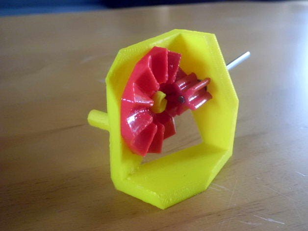
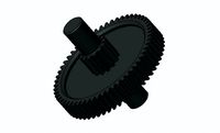
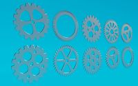
This is an example to make any gears by a gearcutting process. I've worked in the idea of parkinbot.
Crown gears are not a kind of bevel gears. Small gear of crown gears can be moved along it's axis, so there is no precision required. see wikipedia if you need more information.
Very often it is used as cheap gears in toys. Crown gear is made on punched thin sheetmetal. This shape cannot be copied to FDM printing.
Printed thing:
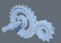
it is printed on the print?.stl files. I have made the holder as a quick and dirty design. Small gear is to small for printed plastic pins, I have used a 3mm steel rod (of a linear slider of an old CD drive). Maybe this gears can be used for educational. I don't see annother practical use.
stl files:
Most problem is the work style of openscad. It generates the cutting tool 100 times and seperately all its vertices to memory.
Then it makes a calculation process to find out the final shape of the object. This results in a very long rendering time because of nested for() loops. Most time I've got in my trials is >1 hour at a 100teeth gear. The mathematical system is very simple. Most work is needed to find out the computational limits and workarounds.
load crown.scad, uncomment gear1().
render [F6] and generate .stl files
uncomment crown_gear().
render [F6] and generate .stl files
load print.scad
select module you want to render and generate .stl files
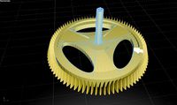
I have made this 2-step process because it would be hard to design the holder when the crown gear needs to be rendered every time. Also, I have found out, creating the crown gear needs a simple hull cylinder. Inserting spokes and hubs will need more computational power and patience of programmer. It's better to do this at a second process.
(I'm happy to get this solution, even it was a hard process with repairs of non manifold stl's)
I have tested to make high tooth count. This is not perfect for educational use. Characteristics of the crown gear system can be seen better at smaller tooth count.
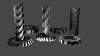
Also, I have tested to make hypoid and bevel gears in the crown cutting process. Hypoid gears normally require a twisted small gear, this will have a lot more vertices and data. So I have used a linear small gear, it will have more compromizes. Bevel crown gear needs some bugfixes. Because I'm working at annother idea to cut real bevel gears, I have not finished the work at bevel crown gears. (It would be a combination of a small spur gear and a crown gear in a matching angle <> 90deg). You will see the result if you'll change the parameters in scad file.
A basic idea in my work on a gear library is the origin point [x,y,z]=[0,0,0]. Axis of the gears will match in the origin point of coordinate system. Position of the thick_end of gears is not needed to make teethcutting process. Gears can be moved easily by translate() and rotate() commands to every point you need.
Annother idea: It is possible to make gears with irregular teeth if you change the tool gear (linear_extrude command) to import of your own gear stl file. Feel free to play with.
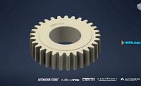
gears.scad is a copy of parkinbot's Gear cutting. I have made a change to smoothen the foot of teeth. This will reduce data by 5%.
https://youtu.be/qEten7H_u-A
Crown gears are not a kind of bevel gears. Small gear of crown gears can be moved along it's axis, so there is no precision required. see wikipedia if you need more information.
Very often it is used as cheap gears in toys. Crown gear is made on punched thin sheetmetal. This shape cannot be copied to FDM printing.
Printed thing:
it is printed on the print?.stl files. I have made the holder as a quick and dirty design. Small gear is to small for printed plastic pins, I have used a 3mm steel rod (of a linear slider of an old CD drive). Maybe this gears can be used for educational. I don't see annother practical use.
stl files:
Most problem is the work style of openscad. It generates the cutting tool 100 times and seperately all its vertices to memory.
Then it makes a calculation process to find out the final shape of the object. This results in a very long rendering time because of nested for() loops. Most time I've got in my trials is >1 hour at a 100teeth gear. The mathematical system is very simple. Most work is needed to find out the computational limits and workarounds.
load crown.scad, uncomment gear1().
render [F6] and generate .stl files
uncomment crown_gear().
render [F6] and generate .stl files
load print.scad
select module you want to render and generate .stl files
I have made this 2-step process because it would be hard to design the holder when the crown gear needs to be rendered every time. Also, I have found out, creating the crown gear needs a simple hull cylinder. Inserting spokes and hubs will need more computational power and patience of programmer. It's better to do this at a second process.
(I'm happy to get this solution, even it was a hard process with repairs of non manifold stl's)
I have tested to make high tooth count. This is not perfect for educational use. Characteristics of the crown gear system can be seen better at smaller tooth count.
Also, I have tested to make hypoid and bevel gears in the crown cutting process. Hypoid gears normally require a twisted small gear, this will have a lot more vertices and data. So I have used a linear small gear, it will have more compromizes. Bevel crown gear needs some bugfixes. Because I'm working at annother idea to cut real bevel gears, I have not finished the work at bevel crown gears. (It would be a combination of a small spur gear and a crown gear in a matching angle <> 90deg). You will see the result if you'll change the parameters in scad file.
A basic idea in my work on a gear library is the origin point [x,y,z]=[0,0,0]. Axis of the gears will match in the origin point of coordinate system. Position of the thick_end of gears is not needed to make teethcutting process. Gears can be moved easily by translate() and rotate() commands to every point you need.
Annother idea: It is possible to make gears with irregular teeth if you change the tool gear (linear_extrude command) to import of your own gear stl file. Feel free to play with.
gears.scad is a copy of parkinbot's Gear cutting. I have made a change to smoothen the foot of teeth. This will reduce data by 5%.
https://youtu.be/qEten7H_u-A
Similar models
cg_trader
$2

mechanical gears
...ne part having cut teeth
spur, helical, double helical, bevel, spiral bevels, hypoid, crown, worm, rack and pinion, harmonic gear
grabcad
free

Helical Bevel Gear
...o change the direction of a shaft's rotation. bevel gears have teeth that are available in straight, spiral, or hypoid shape.
thingiverse
free

small inline gear box v2 by caj
... that are bent and rusty if you use these type of nails the gears will wear realy fast that stuff acts like sand paper to plastic
grabcad
free

Hypoid gear
... pitch surface is best described as a hyperboloid. a hypoid gear can be considered a cross between a bevel gear and a worm drive.
thingiverse
free

Parametric Bevel Gears by wayland
... there are not actually red and blue lines piercing the gear.
edited: gear teeth can now be triangular or fractionally triangular
grabcad
free

#Bevel Gears
...d. straight bevel gear teeth actually have the same problem as straight spur gear teeth -- as each tooth engages, it impacts the…
thingiverse
free

Reuleaux Planetary gear by faggahz
... around (instead of a toothbar).
twin projects:https://www.thingiverse.com/thing:1439718https://www.thingiverse.com/thing:1414403
thingiverse
free

Working moving gears by ESalamanca
...he gear caps that really mean pins to hold them in place. those two file need to be printed two time because there are two gears.
thingiverse
free

Broken Heart by GregFrost
... bit of a process generating the stls from them.
if someone wants to collaborate on a better way to mount the gears, let me know.
grabcad
free

Bevel_Gear_Set
...r.
6. if you failed to generate gear set even when you follow the all guidelines above, try the ctrl+g button again! thank you!
Gearcutting
thingiverse
free

Asymmetric Planetary Gear by faggahz
...i have made this for a test of parkinbot's gearcutting library. please print this only with xy-size compensation of...
thingiverse
free
Reuleaux Planetary gear by faggahz
...source files and opensource. what's not new: idea of gearcutting i have seen this at user:parkinbot. this is not...
Faggahz
thingiverse
free

Pyraminx sphere by faggahz
...required, no springs.
lubrificate with vaseline. puzzle runs good.
more puzzles here: https://www.thingiverse.com/faggahz/designs
thingiverse
free

Jings Pyraminx Sphere by faggahz
...required, no springs.
lubrificate with vaseline. puzzle runs good.
more puzzles here: https://www.thingiverse.com/faggahz/designs
thingiverse
free

Jings Pyraminx 1 by faggahz
...required, no springs.
lubrificate with vaseline. puzzle runs good.
more puzzles here: https://www.thingiverse.com/faggahz/designs
thingiverse
free

Pyraminx by faggahz
...748971https://www.thingiverse.com/thing:2752158https://www.thingiverse.com/thing:2749991https://www.thingiverse.com/thing:2748069
thingiverse
free

horizontal eggcup by faggahz
...re exclusive on your table, it tastes much better, it is fine art.
( example is printed in pla with manual filament color change)
thingiverse
free

Edge Cover Decoration by faggahz
...f.
edge decoration element symmetric and asymmetric.
print in vase mode (slic3r)
cut 1mm at printbed side
pla white / translucent
thingiverse
free

Jings Pyraminx 2 by faggahz
...required, no springs.
lubrificate with vaseline. puzzle runs good.
more puzzles here: https://www.thingiverse.com/faggahz/designs
thingiverse
free

Trabant Sachsenring Car Logo by faggahz
...e
trabant (east german car) logo
printed in pla silver grey
"radmutter": please make a test print, scale for best fit.
thingiverse
free

Gearcube Globe Holder by faggahz
...wo halves, glue together. prints without support.
scad file will create only one half. other side is mirrored using repetierhost.
thingiverse
free

Wash Machine Gift Box by faggahz
...ts without support. there is a 0.2mm gap between box and lid for xy-compensation of the printer. can be removed in the scad file.
Crown
3d_export
$5

Crown
...crown
3dexport
crown
design_connected
$16

Crown
...crown
designconnected
nemo crown computer generated 3d model. designed by jehs+laub.
3d_export
$25

Crown
...crown
3dexport
crown of rose gold with diamonds. programs used: 3ds max, zbrush, corona render
turbosquid
$7

crown
...turbosquid
royalty free 3d model crown for download as blend on turbosquid: 3d models for games, architecture, videos. (1568306)
turbosquid
$2

crown
...n
turbosquid
royalty free 3d model crown for download as c4d on turbosquid: 3d models for games, architecture, videos. (1177593)
turbosquid
$2

Crown
...n
turbosquid
royalty free 3d model crown for download as obj on turbosquid: 3d models for games, architecture, videos. (1634685)
turbosquid
$1

CROWN
...turbosquid
royalty free 3d model crown for download as blend on turbosquid: 3d models for games, architecture, videos. (1490916)
turbosquid
$7

Crown
...quid
royalty free 3d model crown for download as obj and dae on turbosquid: 3d models for games, architecture, videos. (1617936)
turbosquid
$6

Crown
...quid
royalty free 3d model crown for download as obj and ztl on turbosquid: 3d models for games, architecture, videos. (1404084)
3ddd
$1

Toyota Crown
...toyota crown
3ddd
toyota
toyota crown
Process
3ddd
$1
Process unit
...process unit
3ddd
статуэтка
process unit
3d_export
$10

stamping process
...stamping process
3dexport
3d_export
$7

a product processing machine
...a product processing machine
3dexport
a product processing machine
3d_export
$7

Auto Rim Processing Machine
...auto rim processing machine
3dexport
auto rim processing machine
turbosquid
$20

stage launching procession
... free 3d model stage launching procession for download as max on turbosquid: 3d models for games, architecture, videos. (1581910)
3d_export
$17

automobile welding parts processing tooling
...automobile welding parts processing tooling
3dexport
automobile welding parts processing tooling
3d_export
$10

processing equipment for automobile wheel rim
...processing equipment for automobile wheel rim
3dexport
processing equipment for automobile wheel rim
turbosquid
$7

Micro Processing Unit (MPU)
... available on turbo squid, the world's leading provider of digital 3d models for visualization, films, television, and games.
3d_export
$15
automatic processing line for gearbox pump body
...automatic processing line for gearbox pump body
3dexport
automatic processing line for gearbox pump body
turbosquid
$15

Industrial lamp, processing of mechanical parts
...rial lamp, processing of mechanical parts for download as max on turbosquid: 3d models for games, architecture, videos. (1519481)
Gears
3d_ocean
$4
Gears
...gears
3docean
gear gears iron
4 different size of gears
3d_export
$5
gear
...gear
3dexport
gear
3d_export
free
Gears
...gears
3dexport
gears
3d_export
$5
gear
...gear
3dexport
a simple model of gear
3d_export
$5
gear
...gear
3dexport
gear for transmission , case machine
3d_ocean
$3
Gears
...nical parts process steampunk vehicle wheel work
10 different gear models volume 01-10 files: .3ds .c4d .obj note: you need vray
3d_ocean
$1

Spur Gear
...spur gear
3docean
decoration gear
a typical spur gear
3d_ocean
$4
Gear wheels
...gear wheels 3docean engine engineering gear gears industry machinery mechanical toothwheel wheel pair of gear wheels...
turbosquid
$9
Gear
...gear
turbosquid
royalty free 3d model gear for download as on turbosquid: 3d models for games, architecture, videos. (1712328)
turbosquid
$2
Gears
...rs
turbosquid
royalty free 3d model gears for download as ma on turbosquid: 3d models for games, architecture, videos. (1166710)