Thingiverse
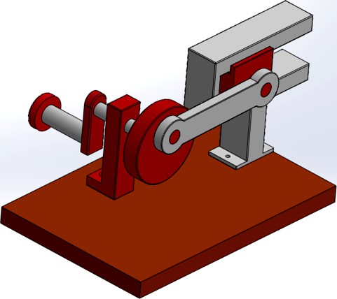
Crank Mechanical System by Kazemoto
by Thingiverse
Last crawled date: 3 years, 3 months ago
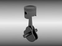
A crank is an arm attached at a right angle to a rotating shaft by which circular motions is imparted to or received from the shaft. When combined with a connecting rod, it can be used to convert circular motion into reciprocating motion, or vice versa. The arm may be a bent portion of the shaft, or a separate arm or disk attached to it. Attached to the end of the crank by a pivot is a rod, usually called a connecting rod (conrod).
The term often refers to a human-powered crank which is used to manually turn an axle, as in a bicycle crank set or a brace and bit drill. In this case a person's arm or leg serves as the connecting rod, applying reciprocating force to the crank. There is usually a bar perpendicular to the other end of the arm, often with a freely rotatable handle or pedal attached.
Familiar examples of crank systems include:
• Mechanical pencil sharpener
• Fishing reel and other reels for cables, wires, ropes, etc.
• Starting Handle for older cars
• Manually operated car window
• The carpenter's brace is a compound crank.
• The crank set that drives a handcycle through its handles.
• Hand winches
Slider-crank mechanism, arrangement of mechanical parts designed to convert straight-line motion to rotary motion, as in a reciprocating piston engine, or to convert rotary motion to straight-line motion, as in a reciprocating piston pump. The basic nature of the mechanism and the relative motion of the parts can best be described with the aid of the accompanying figure 5, in which the moving parts are lightly shaded. The darkly shaded part 1, the fixed frame or block of the pump or engine, contains a cylinder, depicted in cross section by its walls DE and FG, in which the piston, part 4, slides back and forth. The small circle at A represents the main crankshaft bearing, which is also in part 1. The crankshaft, part 2, is shown as a straight member extending from the main bearing at A to the crankpin bearing at B, which connects it to the connecting rod, part 3. The connecting rod is shown as a straight member extending from the crankpin bearing at B to the wristpin bearing at C, which connects it to the piston, part 4, which is shown as a rectangle. The three bearings shown as circles at A, B, and C permit the connected members to rotate freely with respect to one another. The path of B is a circle of radius AB; when B is at point h the piston will be in position H, and when B is at point j the piston will be in position J. On a gasoline engine, the head end of the cylinder (where the explosion of the gasoline-air mixture takes place) is at EG; the pressure produced by the explosion will push the piston from position H to position J; return motion from J to H will require the rotational energy of a flywheel attached to the crankshaft and rotating about a bearing collinear with bearing A. On a reciprocating piston pump the crankshaft would be driven by a motor.
Similar models
grabcad
free

crankshaft
... motion and rotational motion. in a reciprocating engine, it translates reciprocating motion of the piston into rotational motion
grabcad
free

CRANK SHAFT
...ly used in internal combustion engines and consist of a series of cranks and crankpins to which the connecting rods are attached.
grabcad
free

Crank Shaft
...ly used in internal combustion engines and consist of a series of cranks and crankpins to which the connecting rods are attached.
grabcad
free

Crank Shaft
...ly used in internal combustion engines and consist of a series of cranks and crankpins to which the connecting rods are attached.
grabcad
free

Crank shaft
...nly used in internal combustion engines and consist of a series of cranks and crankpins to which the connecting rods are attached
cg_trader
$10

Automotive Crankshaft Part | 3D
...ing surfaces whose axis is offset from that of the crank, to which the big ends of the connecting rods from each cylinder attach.
grabcad
free

crankshaft
...r, it converts the rotational motion into reciprocating motion. in order to do the conversion between two motions, the crankshaft
grabcad
free

crankshaft
...r, it converts the rotational motion into reciprocating motion. in order to do the conversion between two motions, the crankshaft
grabcad
free

Crank, Crankshaft, shaft, krankşaft.
...f an engine is attached. it is a mechanical part able to perform a conversion between reciprocating motion and rotational motion.
grabcad
free

CrankShaft
...ly used in internal combustion engines and consist of a series of cranks and crankpins to which the connecting rods are attached.
Crank
3d_export
free
crank shaft
...crank shaft
3dexport
crank shaft with piston with different materials
turbosquid
$3
Crank Shaft
...lty free 3d model crank shaft for download as x, ige, and stl on turbosquid: 3d models for games, architecture, videos. (1694841)
turbosquid
$5
Steel Crank
... available on turbo squid, the world's leading provider of digital 3d models for visualization, films, television, and games.
design_connected
$13

Crank 22 End Table
...crank 22 end table
designconnected
four hands crank 22 end table computer generated 3d model.
turbosquid
$50

Wooden Crank Toy
... available on turbo squid, the world's leading provider of digital 3d models for visualization, films, television, and games.
turbosquid
$19

Crank Wheel Highpoly
... available on turbo squid, the world's leading provider of digital 3d models for visualization, films, television, and games.
3d_export
$7
Piston and crank 3D Model
...ycle bearing pulley push rod valve bolt spring screw metal new moped stroke
piston and crank 3d model dragosburian 80941 3dexport
3d_export
$15

Hand Cranked Sharpener 3D Model
...cranked spring office supplies sharp supply tools equipment school writing
hand cranked sharpener 3d model firdz3d 84605 3dexport
3d_export
$9

Crank Wheel 3D Model
...ainless iron industrial machine
crank wheel 3d model download .c4d .max .obj .fbx .ma .lwo .3ds .3dm .stl firdz3d 105897 3dexport
turbosquid
free
Low Poly Crank Gun
...bosquid
free 3d model low poly crank gun for download as fbx on turbosquid: 3d models for games, architecture, videos. (1436642)
Mechanical
3d_export
$50
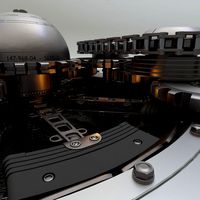
Mechanism
...mechanism
3dexport
mechanism -------- animation is present only in the blender file.
3d_export
$5

mechanics
...mechanics
3dexport
turbosquid
$50

mechanic
... available on turbo squid, the world's leading provider of digital 3d models for visualization, films, television, and games.
3ddd
$1

Mechanical Wasp
...mechanical wasp
3ddd
робот
mechanical wasp
3d_export
$20
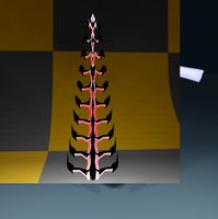
Mechanical tail
...mechanical tail
3dexport
mechanical tail<br>four-part movement
3d_export
$5

mechanical ballista
...mechanical ballista
3dexport
a mechanical ballista useful for medieval or fantasy games does not contain animations
turbosquid
$59

Mechanical Part
...id
royalty free 3d model mechanical part for download as c4d on turbosquid: 3d models for games, architecture, videos. (1410833)
turbosquid
$50

Mechanical Spider
...royalty free 3d model mechanical spider for download as blend on turbosquid: 3d models for games, architecture, videos. (1599864)
turbosquid
$45

Mechanical Pencil
...royalty free 3d model mechanical pencil for download as blend on turbosquid: 3d models for games, architecture, videos. (1503379)
turbosquid
$35

Mechanical fish
...id
royalty free 3d model mechanical fish for download as max on turbosquid: 3d models for games, architecture, videos. (1152530)
System
archibase_planet
free
System
...m
archibase planet
fire alarm system fire alarm box
security light system - 3d model (*.gsm+*.3ds) for interior 3d visualization.
archibase_planet
free
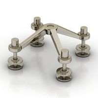
Spider system
...stem spider glass system
spider system to fix glass stefano galli n050912 - 3d model (*.gsm+*.3ds) for interior 3d visualization.
3ddd
$1

Euforia System
...euforia system
3ddd
euforia
euforia system
3d_export
$50

Roof system Truss system 3D Model
...oof system truss system 3d model
3dexport
roof system truss truss stage
roof system truss system 3d model aleksbel 38970 3dexport
3ddd
$1

DVD System
...dvd system
3ddd
dvd , schneider
dvd system
design_connected
free

Seating system
...seating system
designconnected
free 3d model of seating system
3d_export
$5

solar system
...solar system
3dexport
solar system in c4d, with 8k nasa textures
3ddd
$1

Quanta System
...quanta system
3ddd
медицина
quanta system.
лазерное оборудование для медицинских центров
3d_export
$15
solar system
...nd the other the sun, the earth and the moon, the latter has an animation with camera movement included, the files are in spanish
3d_export
$14

missile system
...missile system
3dexport