Thingiverse
CR-6SE Direct Drive Conversion by BostonBowser
by Thingiverse
Last crawled date: 3 years, 3 months ago
September 21st, 2020 Update:
I've added files for a cable guide. You need to print the Cable Guide and Cable Guide Stud. Print in the orientation they import in. There are no special settings to consider. You need a M3 hex nut and a M3x12 socket head cap screw. Installs on the far left hexagonal cutout above the cover for the X-axis pulley.
A filament spool holder with filament runout sensor is in the works.
September 16th, 2020 Update:
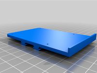
I've added a file named "Base Plate(no dd)" for those who don't want to convert to direct drive, shave a few grams off the weight of their X axis assembly, and upgrade to a 5015 radial fan. Follow the same steps noted below, just omit the steps pertaining to the direct drive conversion, omit an M3 hex nut and the M3x12 screw, and swap the M3x50 screw for an M3x40 one.
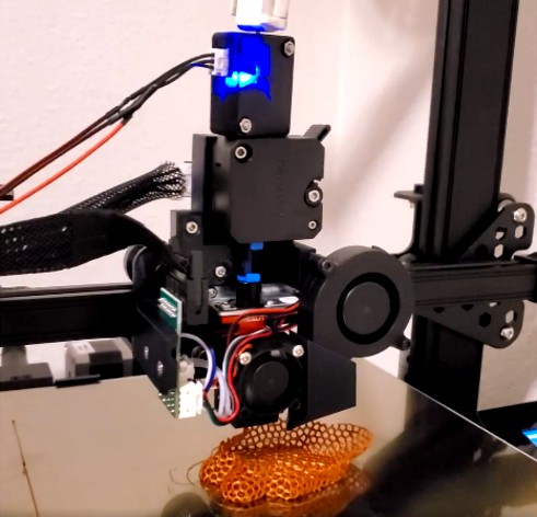
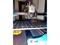
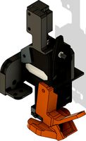
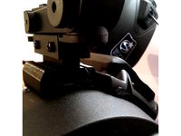
This is a direct drive conversion for the Creality CR-6SE.
Keep in mind that this isn't a beginner level modification and that this will void whatever warranty your machine has. If done incorrectly you could potentially damage your machine. I'm not responsible for any damages if you download and attempt installation. That being said...
Things you will need:
M3x50 Socket Head Cap Screw 1x
M3x40 Socket Head Cap Screw 1x
M5x30 Socket Head Cap Screw 2x
M3x8 Socket Head Cap Screw 6x
M3x12 Socket Head Cap Screw 1x
M3 Hex Nut Socket Head Cap Screw 6x
One 24v 5015 radial fan
One 25mm thick stepper motor (link to the one I used included)
Installation:
Completely break down the X axis back plate assembly including the top two roller wheels.
Replace the screws for the top two roller wheels with M5x30 socket head cap screws.
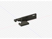
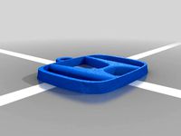
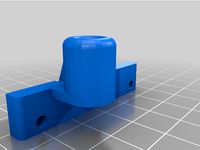
Install the Button in the hole in the X axis back plate.
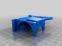
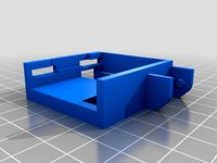
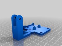
Install Base Plate.
Install X axis board.
Install hotend with strain gauge bracket.
Plug everything in to the X axis board (you may need to reverse the polarity on the 5015 radial fan).
Break down the extruder assembly.
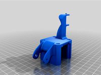
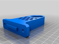
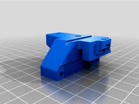
Install extruder and stepper motor onto the Extruder Bracket with the stepper motor connector facing the X axis end stop and the extruder lever facing the X axis tensioner.
Cut and install a longer length of PTFE tubing than you think you will need into the hotend.
Install Extruder Bracket assembly by sliding it onto the PTFE tube in the hotend and adjust the length of tube until the screw holes on the Extruder Bracket assembly line up with the matching screw holes on the Base Plate.
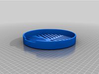
Slip fan duct onto output duct of 5015 radial fan.
Install 5015 radial fan.
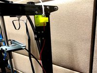
Remove the glue from the X axis connectors behind the X axis motor and remove the stepper and filament runout sensor cables.
If you use the motor linked below, swap the middle two wires and extend the stepper cable by splicing appropriately sized wire into the original cable (you can use a pre-made extension cable, just don't mix up the wiring for the motor)
Extend the filament runout sensor cable using the same method as above.
Plug in the stepper motor and filament runout sensor.
Notes:
I don't have a mount made for the runout sensor or a top mount for a filament spool. Ideally the runout sensor would be on top of the machine and out of the way of the direct drive assembly.
I don't have a mount made to manage the wires. A 100mm Allen wrench duct taped to the cover for the toothed X axis pulley works well.
I messed with my E axis vref a bit and changed it to 1.00v. I don't know what it originally was, but that's what I set it to. If you're worried about the motor getting too hot, let your machine run for a while and touch your Y axis motor. Realistically you should use your judgement here and adjust your extruder vref to what you think is safe.
I'm sorry I didn't measure the exact length of PTFE tube needed.
The fan duct was thrown together in maybe ten minutes and has not been CFD tested like some of the fancier fan ducts. Air blows below the nozzle and that's about as much as I hoped for when designing and testing.
A step file of the CAD assembly is included if you're into that sort of thing.
Please comment if you have questions, concerns, or other feedback and I will try to regularly monitor this Thing.
Link to the stepper motor I used:
https://www.amazon.com/gp/product/B01LESPDCQ/ref=ppx_yo_dt_b_asin_title_o04_s00?ie=UTF8&psc=1
I've added files for a cable guide. You need to print the Cable Guide and Cable Guide Stud. Print in the orientation they import in. There are no special settings to consider. You need a M3 hex nut and a M3x12 socket head cap screw. Installs on the far left hexagonal cutout above the cover for the X-axis pulley.
A filament spool holder with filament runout sensor is in the works.
September 16th, 2020 Update:
I've added a file named "Base Plate(no dd)" for those who don't want to convert to direct drive, shave a few grams off the weight of their X axis assembly, and upgrade to a 5015 radial fan. Follow the same steps noted below, just omit the steps pertaining to the direct drive conversion, omit an M3 hex nut and the M3x12 screw, and swap the M3x50 screw for an M3x40 one.
This is a direct drive conversion for the Creality CR-6SE.
Keep in mind that this isn't a beginner level modification and that this will void whatever warranty your machine has. If done incorrectly you could potentially damage your machine. I'm not responsible for any damages if you download and attempt installation. That being said...
Things you will need:
M3x50 Socket Head Cap Screw 1x
M3x40 Socket Head Cap Screw 1x
M5x30 Socket Head Cap Screw 2x
M3x8 Socket Head Cap Screw 6x
M3x12 Socket Head Cap Screw 1x
M3 Hex Nut Socket Head Cap Screw 6x
One 24v 5015 radial fan
One 25mm thick stepper motor (link to the one I used included)
Installation:
Completely break down the X axis back plate assembly including the top two roller wheels.
Replace the screws for the top two roller wheels with M5x30 socket head cap screws.
Install the Button in the hole in the X axis back plate.
Install Base Plate.
Install X axis board.
Install hotend with strain gauge bracket.
Plug everything in to the X axis board (you may need to reverse the polarity on the 5015 radial fan).
Break down the extruder assembly.
Install extruder and stepper motor onto the Extruder Bracket with the stepper motor connector facing the X axis end stop and the extruder lever facing the X axis tensioner.
Cut and install a longer length of PTFE tubing than you think you will need into the hotend.
Install Extruder Bracket assembly by sliding it onto the PTFE tube in the hotend and adjust the length of tube until the screw holes on the Extruder Bracket assembly line up with the matching screw holes on the Base Plate.
Slip fan duct onto output duct of 5015 radial fan.
Install 5015 radial fan.
Remove the glue from the X axis connectors behind the X axis motor and remove the stepper and filament runout sensor cables.
If you use the motor linked below, swap the middle two wires and extend the stepper cable by splicing appropriately sized wire into the original cable (you can use a pre-made extension cable, just don't mix up the wiring for the motor)
Extend the filament runout sensor cable using the same method as above.
Plug in the stepper motor and filament runout sensor.
Notes:
I don't have a mount made for the runout sensor or a top mount for a filament spool. Ideally the runout sensor would be on top of the machine and out of the way of the direct drive assembly.
I don't have a mount made to manage the wires. A 100mm Allen wrench duct taped to the cover for the toothed X axis pulley works well.
I messed with my E axis vref a bit and changed it to 1.00v. I don't know what it originally was, but that's what I set it to. If you're worried about the motor getting too hot, let your machine run for a while and touch your Y axis motor. Realistically you should use your judgement here and adjust your extruder vref to what you think is safe.
I'm sorry I didn't measure the exact length of PTFE tube needed.
The fan duct was thrown together in maybe ten minutes and has not been CFD tested like some of the fancier fan ducts. Air blows below the nozzle and that's about as much as I hoped for when designing and testing.
A step file of the CAD assembly is included if you're into that sort of thing.
Please comment if you have questions, concerns, or other feedback and I will try to regularly monitor this Thing.
Link to the stepper motor I used:
https://www.amazon.com/gp/product/B01LESPDCQ/ref=ppx_yo_dt_b_asin_title_o04_s00?ie=UTF8&psc=1
Similar models
thingiverse
free
Bluer Plus BMG Direct Drive with dual 5015 radial by wampelt
.... other parts can print with pla.
extra part needed will be longer stepper motor cable and filament runout sensor cable.
enjoy !
thingiverse
free

Interchangeable Dual 2 Blower Radial 5015 Fan Duct 90 by bofus
...ngiverse
i design this 90 degree fan duct since i have a direct extruder and the fans wouldnt fit because of the stepper motor..
thingiverse
free
Original Prusa MK3 Delta-P Fan Extruder by 09labs
...radial fan)
test filament : prusament petg carmine red
temperature : 240 / 90
nozzle : 0.4mm
outline, top, bottom layer count : 4
thingiverse
free
Filament guide
...de
thingiverse
filament guide to install in place of extruder stepper motor on filament sensor bracket for direct drive upgrade.
thingiverse
free
Ender 3 Filament Runout Sensor for dual drive extruder by PrOOnOOb
... runout sensor mount for dual drive extruder you also need two m3x20 screws and nuts to mount the sensor.
installed on ender 3 v2
thingiverse
free
Satsana Ender 3V2 with Direct Drive Conversion by bgyen
...
parts: 4020 fan (screws for fan), 5015 blower fan (screw for fan), 1xm3 8mm screw to attach fan duct to the direct drive bracket
thingiverse
free
Updated Cable Chain End-Stopper-Mount for CTC / Flashforge / Replicator by MacNite
...der-carrier (better: the fun duct) 'crashed' into the stepper-motor-housing preventing the carrier to reach the end-stop.
thingiverse
free
Direct Drive Cable Chain connector Ender 3 Series by Fr1day
...lder
removed the filament guide from the direct drive extruder holder to make it usable for every extruder (dual gear in my case)
thingiverse
free
BTT Filament runout sensor for Micro Swiss Direct Drive by ptsiampas
...mount without the roller if you don't want to use it.
i have been using it for over 2 months and it's still going strong.
thingiverse
free
Ender 3 pro Direct - E3D V6, fan duct Prusa mini design, runout sensor, BLTOUCH, 5015 Fan by Tomas633
...11.0.0.27424c4dv1tn6b
marlin settings
define x_min_pos -10.75
define y_min_pos -25
define nozzle_to_probe_offset { -20, 14.5, 0 }
Bostonbowser
thingiverse
free

Nismo Keychain by BostonBowser
... photo of the nismo logo. i don't own nissan and don't intend to sell these for commercial purposes (and nor should you).
thingiverse
free
Mazda Keychain by BostonBowser
...e photo of the mazda logo. i don't own mazda and don't intend to sell these for commercial purposes (and nor should you).
thingiverse
free

Mitsubishi Keychain by BostonBowser
... the mitsubishi logo. i don't own mitsubishi and don't intend to sell these for commercial purposes (and nor should you).
thingiverse
free

Mopar Keychain by BostonBowser
...e photo of the mopar logo. i don't own mopar and don't intend to sell these for commercial purposes (and nor should you).
thingiverse
free

Nissan Keychain by BostonBowser
...photo of the nissan logo. i don't own nissan and don't intend to sell these for commercial purposes (and nor should you).
thingiverse
free
Subaru Keychain by BostonBowser
...photo of the subaru logo. i don't own subaru and don't intend to sell these for commercial purposes (and nor should you).
thingiverse
free

Volkswagen Keychain by BostonBowser
... the volkswagen logo. i don't own volkswagen and don't intend to sell these for commercial purposes (and nor should you).
thingiverse
free

Ford Keychain by BostonBowser
...nce photo of the ford logo. i don't own ford and don't intend to sell these for commercial purposes (and nor should you).
thingiverse
free
Honda Keychain by BostonBowser
...e photo of the honda logo. i don't own honda and don't intend to sell these for commercial purposes (and nor should you).
thingiverse
free

Datsun Keychain by BostonBowser
...tsun (nor does datsun lolol shout out to nissan) and don't intend to sell these for commercial purposes (and nor should you).
6Se
thingiverse
free
CR-6SE tube holder by jeff_lin
...cr-6se tube holder by jeff_lin
thingiverse
tube support for cr-6se printer
thingiverse
free

Duncan Mask Celestron Nexstar 6SE
...duncan mask celestron nexstar 6se
thingiverse
ducan mask to collimate celestron nexstar 6se
thingiverse
free
Shorter CR-6SE topmount spool holder by andersje
...ing with tinkercad, and now this sits low enough to sit inside my cabinet, and it doesn't interfere with the x gantry at all.
thingiverse
free
Celestron Nexstar 6SE Focus Knob by CXHXVN
...celestron nexstar 6se focus knob by cxhxvn
thingiverse
with this knob you don't need to remove the rubber grip.
have fun!
thingiverse
free

CR-6SE y end stop for linear rail by jeff_lin
...cr-6se y end stop for linear rail by jeff_lin
thingiverse
for y axis use linear rail
thingiverse
free
Celestron 6SE Starsense & finder adapter by Spretrep
...s with the celestron 6se in the shoe you can download an adapter here
you'll need a 3mm nut and bolt to secure the scope shoe
thingiverse
free
Bahtinov Mask for Celestron 6SE or 6" Evolution by ScottSieke
...tron 6se or 6" evolution by scottsieke
thingiverse
bahtinov mask to aid and improve focus on a 6" celestron telescope.
thingiverse
free
CR-6SE Raspberry Pi Rail Mount Case by kevfquinn
... - it's fine for my raspberry pi 3b, but can't say if it would be good for the raspberry pi 4 which can run a lot hotter.
thingiverse
free
CR-6SE Sherpa extruder Direct drive conversion by athlon789789
...aliexpress.com/item/1005002487727392.html
sherba mini extruder designer:https://github.com/annex-engineering/sherpa_mini-extruder
thingiverse
free
Celestron Nexstar 6SE HC base for AUX splitter
...lescope.
you'll need:
10 m3 nuts
12 washers
4 m3x30mm screws (corners)
4 m3x10mm screws (top_holder)
2 m3x20mm screws (sides)
Cr
turbosquid
$15
Creazioni CR-673 CR-4461
... available on turbo squid, the world's leading provider of digital 3d models for visualization, films, television, and games.
3ddd
$1
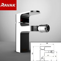
Ravak CR 055.00
...ravak cr 055.00
3ddd
ravak , смеситель
ravak cr 055.00
turbosquid
$100

CR-002
...
turbosquid
royalty free 3d model cr-002 for download as stl on turbosquid: 3d models for games, architecture, videos. (1686037)
3ddd
$1

Ravak CR 012.00
...ravak cr 012.00
3ddd
ravak , смеситель
смеситель ravak cr 012.00
3ddd
free
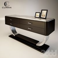
Консоль CR Currin
...ь , cr currin
консоль cr currin
ширина - 1675 мм
глубина - 510 мм
общая высота - 810 мм
3ddd
$1

CR 39444
...0
диаметр: 100
тип патрона: gu5,3 gu10
количество ламп: 1
мощность: 35w
цвет: золото хрусталь
материал: металл хрусталь exclusive
3d_ocean
$89

Honda CR-Z
...www.youtube.com/watch?v=rrbb4d4lypk ` he honda cr-z‘s exterior styling is formed around a “one-motion wedge” concept with a lo...
3ddd
$1

Creazoni / STEFY CR-8901
...creazoni / stefy cr-8901
3ddd
creazoni
creazioni stefy cr-8901
turbosquid
$60

Chain-CR-001
...squid
royalty free 3d model chain-cr-001 for download as stl on turbosquid: 3d models for games, architecture, videos. (1680536)
turbosquid
$99

Honda CR-Z
... available on turbo squid, the world's leading provider of digital 3d models for visualization, films, television, and games.
Conversion
3ddd
$1

Conversation Seat
...шетка
the conversation seat made in englandhttp://www.squintlimited.com/products/the_conversation_seat/gold
+ max 2011
3d_export
$10

Converse 3D Model
...converse 3d model
3dexport
converse shoe pc unix mac
converse 3d model electropainter17075 38067 3dexport
turbosquid
$100

converse-shoe
...quid
royalty free 3d model converse-shoe for download as c4d on turbosquid: 3d models for games, architecture, videos. (1398427)
turbosquid
$10

Conversation Furniture
... available on turbo squid, the world's leading provider of digital 3d models for visualization, films, television, and games.
turbosquid
$7

Converse Allstars
... available on turbo squid, the world's leading provider of digital 3d models for visualization, films, television, and games.
design_connected
$16

Conversation Club Chair
...conversation club chair
designconnected
donghia conversation club chair chairs computer generated 3d model. designed by n/a.
design_connected
$27

Hemicycle Conversation Chair
...rsation chair
designconnected
ligne roset hemicycle conversation chair computer generated 3d model. designed by nigro, philippe.
3d_export
$24

Converse keds 3D Model
...converse keds 3d model
3dexport
converse all star ked shoe clothes sports
converse keds 3d model vermi1ion 26201 3dexport
3ddd
$1

Converse All-Star Shoes
...converse all-star shoes
3ddd
кеды , обувь
converse all-star shoes
design_connected
$18

CONVERSE Jack Purcell Sneakers
...converse jack purcell sneakers
designconnected
converse jack purcell sneakers computer generated 3d model.
Direct
design_connected
free
Compas Direction
...compas direction
designconnected
free 3d model of compas direction by vitra designed by prouvé, jean.
design_connected
$18

Direction Pivotant
...direction pivotant
designconnected
vitra direction pivotant computer generated 3d model. designed by prouvé, jean.
turbosquid
$6
not direct the front
...oyalty free 3d model not direct the front for download as max on turbosquid: 3d models for games, architecture, videos. (1213034)
turbosquid
$10

Rails Direct
... available on turbo squid, the world's leading provider of digital 3d models for visualization, films, television, and games.
3d_export
$5

Picto toilet directions
...lude 3d files next to rhino6: x3dv, step, igus, obj and stl. double-sided, flipping changes the gender directions to the toilets.
3ddd
$1
fauteuli direction
...d
chair , vitra , fauteuli
fauteuli vitra chair
design_connected
$18

Fauteuil Direction, 1951
...fauteuil direction, 1951
designconnected
vitra fauteuil direction, 1951 computer generated 3d model. designed by prouvé, jean.
3d_export
$5
Directional tactile 3D Model
...tactile 3d model
3dexport
directional tactile braille tile flooring interior
directional tactile 3d model renob000 71068 3dexport
turbosquid
$26

Radio direction finder A
...ty free 3d model radio direction finder a for download as fbx on turbosquid: 3d models for games, architecture, videos. (1212490)
turbosquid
$7

Wooden direction signage
...ty free 3d model wooden direction signage for download as max on turbosquid: 3d models for games, architecture, videos. (1453747)
Drive
turbosquid
$90
Drive
...turbosquid
royalty free 3d model drive for download as blend on turbosquid: 3d models for games, architecture, videos. (1654393)
3d_export
$10

cycloidal drive
...cycloidal drive
3dexport
cycloidal drive
3d_ocean
$5
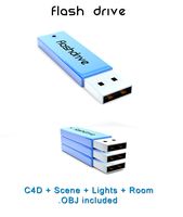
Flash Drive
...h drive included : – materials – scene ( lighs / room ) – .c4d + .obj for any questions please feel free to contact me thank you.
3d_ocean
$5

Usb drive
...s shaders and a lighting setup. it also has a small animation of it going in and out. i saved it out as both a .blend file and...
3d_ocean
$5

Pen Drive
...est computer drive game model good low poly new pen pen drive textured unwrapped uv very low poly
a very beautiful low poly model
3d_ocean
$10

External hard drive
... is a detailed model of a trekstor external hard drive. you can easily modify the label on the top. simply edit the text objects.
turbosquid
$60

Star Drive
...squid
royalty free 3d model star drive for download as blend on turbosquid: 3d models for games, architecture, videos. (1254314)
turbosquid
$50

Star Drive
...squid
royalty free 3d model star drive for download as blend on turbosquid: 3d models for games, architecture, videos. (1263524)
turbosquid
$45
Star Drive
...squid
royalty free 3d model star drive for download as blend on turbosquid: 3d models for games, architecture, videos. (1287060)
turbosquid
$40
Star Drive
...squid
royalty free 3d model star drive for download as blend on turbosquid: 3d models for games, architecture, videos. (1261902)