Thingiverse
CR-10S "The Last Stand" Mod by Prostakarnik
by Thingiverse
Last crawled date: 2 years, 11 months ago
"The Last Stand" Mod
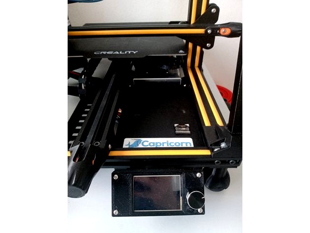
As the name suggests, this is a stand alone mod for the Creality CR-10S, which allows the instalation of the BTT SKR v1.4 (turbo) board, a Pi4 (not included in this build) and the BTT TFT24 touch screen display.
This mod includes only the items necessary for removing the control box. All other mods (uprights, tensioners, fan duckt) you can see on screen are not mine, but i can link them if there is enough interest.
WARNING!!!
THIS IS NOT A SIMPLE PROJECT! DISASSEMBLE YOUR PRINTER AT YOUR OWN RISK! I AM NOT RESPONSIBLE FOR ANY DAMAGE YOU, YOUR PROPERTY OR OTHER 3RD PARTY INDIVIDUALS MIGHT SUFFER WHILE UNDERTAKING THIS PROJECT!
Ok, now that I have that out of the way, lets talk about the hardware needed before you stard actually printing.
Wire strippers
Soldering iron and solder - for some cable connections.
Multimeter - for checking everything for continuity.
Allen keys
Small screwdriver - for the board terminals.
Crimping pliars for your chosen connectors (JST / Dupont)
JST / Dupont connectors - both should work equally fine, it's down to personal preference.
Generic cable lugs - for the PSU connections (you need the fork connector in particular)
Button Head Nuts and Bolts set (from M2 to M5) - or to be more precice:
6x M3x6 bolt
4x M3x8 bolt
16x M3x12 bolt
30x M4x8 bolts ( 16 of these you can recycle from the original feet)
4x M4x25 bolt (exhaust fan bolts; recycle old ones and/or included with new one)
8x M5x8 bolt
2x M3 hammer nut / extrusion nut
25x M4 hammer nut
8x M5 hammer nut
DOUBLE CHECK FOLLOWING PARAMETERS:
Needed cables for the project (stock 12V, 15A Power Supply Unit):
14 AWG silicone insulated cable - for heated bed
16 AWG silicone insulated cable - for the PSU connections
18 AWG silicone insulated cable - Hot end heater
22 AWG silicone insulated cable - all other logic connections ( steppers, endstops ...)
4x Squash balls
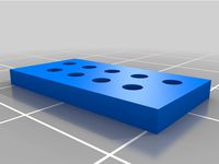
You now will need to print out the parts needed for the project. Do not forget that you also need some cable clips for the frame (I didn't bother designing any because there is more than enough on this website). The display case is a 0 tolerance part, so if it doesn't fit your particular display, you should adjust your thermal expansion settings. You can mix and match colors as you like. I designed all of them so that they can be printed with minimal to no support. For the parts that have contact with heated elements ( PSU, MOSFET, Motherboard) I suggest using PETG. Standard 0.4 mm nozzle and 0.2 mm layer height should work just fine. (Optional: 0.6 mm nozzle and 0.4 mm layer height for faster printing at the minor expense of some quality).
Now that you have everything gathered it's time to start the fun part:
Step 1: Double check you actually have everything! ( Seriously, the last thing you want right now is to need a printed part with your printer disassembled).
Step 2: Disconnect the power and let it sit for a couble of minutes. ( There is a big coil in the PSU which stores some residual power even if the cable isn't plugged in, ask me how I know...)
Step 3: Take a picture with your phone for referance before you start tearing everything appart. Salvage the following items from your original control box:
Power Supply Unit (PSU)
Power Terminal ( where you plug the cable in)
On/Off switch
MOSFET (that small green board at the back with the huge heatsink)
exhaust fan ( if you don't have a new one)
case cooling fan ( again, if you don't have a new one)
4 PIN female connector ( the one your heated bed plugged into)
8 PIN female connector ( the one your hot end plugged into)
All motor/endstop cables ( label these to be sure, as you can easily confuse which end goes where)
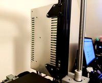
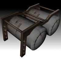
Step 4: Disassemble your printer untill it looks like the reference picture ( Image 1)
Step 5: Mount the squash ball feet to the frame, then tilt it to one side.
17x M4x8 bolts
17x M4 hammer nuts
(no point in putting the squash balls in right now, because they'll just fall off)
Step 6: Screw in the power terminal and press in the on/off switch in their corresponding places on the leg. You can use the original cables that came with them to connect them later to the PSU.
2x M3x8 bolt
Step 7: Solder in new wires and extend the original ones of the 8 PIN connector. Be careful which cable goes where! (Image 3A / 3B)
Soldering iron and solder
18 AWG cable
JST / Dupont connectors
Crimping pliars
Extension rough lenght: for connectors: 50-55 cm, for soldered wires: 60-65 cm (Measure to be sure!)
Step 7A: Solder in new wires and extend the original ones of the 4 PIN connector. Again, be careful of what goes where.
14 AWG cable for heated bed
Extension rough lenght: 50 - 55 cm (Measure to be sure!)
Step 8: Screw in your 8 PIN connector to the bracket and then screw it in place below the z-Stepper motor.
2x M4x8 bolt
2x M4 hammer nut
Step 8A: Screw in your 4 PIN connector to the bracket and then screw it in place at the back side of the printer, ideally right bellow where the heated bed cable comes out.
2x M4x8 bolt
2x M4 hammer nut
You can now connect all your extension cables, but do not bind them together yet, as there are some other cables that you will need too.
Step 9: Make extension cables for the X-Motor, Extruder and X-Endstop.
JST / Dupont connectors
Crimping pliars
Soldering iron
Step 10: Start binding your cables together from the connectors onwards.
For the 8 PIN: From there you should have all the cables from the connector itself and the Z1-motor, Z-Endstop, X-motor, X-Endstop and Extruder ( all connectors should meet at the same point under the frame, as to give you a rough idea of how long to leave the cables before the connector. Keep seperate from the other looms.
For the 4 PIN: Same as above, but the positive power cable for the bed should be shorter and should deviate almost imediately after the central frame member. From that point you will need to bind in the Y-motor, Y-Endstop and Z2-motor cables to this loom. Make sure you leave enough room for the Z2 cables. Keep seperate from the other looms.
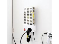
Step 11: Mount the cable cover to the frame. Mount the PSU support clamps to the PSU, but do not bolt it in place for now. Now is the time to route the cable from the PSU to the new control box through the hole in the cover. The new cables should be 40-45 cm long.
2x M4x8
2x M4 hammer nut
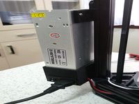
Connect the cables to the PSU ( + power switch and power terminal). Mount the PSU to the frame and inside the cable cover. The mounts should sit flush with the cable cover. Route these wires seperately from the other 2 looms.
Use Image 4 for reference.
Step 12: CHECK ALL CONNECTIOS BEFORE GOING FURTHER! Seriously, use the multimeter to check that everything is in order. Imagine going through all this only to fry the motherboard, for example. Take your time with this step.
Multimeter
Step 13: Take the middle part of the new control box and screw in the exhaust fan. Take the flat cables and mark them with a permanent marker (1 and 2). Place all display cables in their allocated slot in the part, then screw in the bottom plate ( where the motherboard sits).
4x M4x25 bolt ( they cut their own thread so expect resistance)
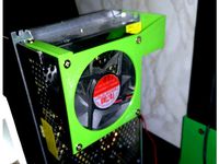
Step 14: Bolt the case to the frame. It should sit flush on 3 sides with a little bit of room between it and the PSU.
4x M5x8 bolt
4x M5 hammer nut
Step 15: Bolt the MOSFET in its place and connect all necessary cables accordingly. (The largest hole in the case is meant for this).
2x M3x6 bolt
Step 16: Insert the cables from the 2 remaining looms through the 2 free holes in the box. ( I chose the PSU side hole to be Heated Bed and the exhaust fan side hole to be Hot End)
Step 17: Connect the cables to the screw terminals on your motherboard before bolting it in place. Make sure you check everything with the corresponding official wiring diagram (not here!)
Small screwdriver
Shorten cables and/or make connections as seen fit. Make sure all cables are under no strain. No cables should be touching the MOSFET Heatsink.
Step 18: CHECK ALL YOUR CONNECTIONS! This should be the final check of everything you have done so far, really take your time and go over everything.
Multimeter
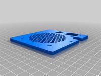
Step 19: Screw in your case cooler fan to the top part of the case. Connect the fan to one of the free terminals and screw the cover in its place.
4x M3x12 bolt
Step 20: Mount the nuts into the case first then fit the display and mount the bracket behind it as shown. ( Image 8A / 8B)
2x M3 nut
4x M3x12 bolt
2x M3x8 bolt
2x M4 Hammer nut
Step 21: Connect the cables to your display. If your are not sure wich of the cables you labeled earlier goes where, you can check the official wiring diagram from the producer. Mount your display on the frame.
Step 22 (Optional): Tidy up your instalation: bind loose cables, use cable clips to optimise routing etc. ...
Hopefully everything should turn on without a hitch and you will now have an upgraded CR-10S wich is virtually silent. Enjoy!
PS: If there are some aspects of the build I missed and/or you find unclear, leave a comment. I will try to adress these as soon as possible.
As the name suggests, this is a stand alone mod for the Creality CR-10S, which allows the instalation of the BTT SKR v1.4 (turbo) board, a Pi4 (not included in this build) and the BTT TFT24 touch screen display.
This mod includes only the items necessary for removing the control box. All other mods (uprights, tensioners, fan duckt) you can see on screen are not mine, but i can link them if there is enough interest.
WARNING!!!
THIS IS NOT A SIMPLE PROJECT! DISASSEMBLE YOUR PRINTER AT YOUR OWN RISK! I AM NOT RESPONSIBLE FOR ANY DAMAGE YOU, YOUR PROPERTY OR OTHER 3RD PARTY INDIVIDUALS MIGHT SUFFER WHILE UNDERTAKING THIS PROJECT!
Ok, now that I have that out of the way, lets talk about the hardware needed before you stard actually printing.
Wire strippers
Soldering iron and solder - for some cable connections.
Multimeter - for checking everything for continuity.
Allen keys
Small screwdriver - for the board terminals.
Crimping pliars for your chosen connectors (JST / Dupont)
JST / Dupont connectors - both should work equally fine, it's down to personal preference.
Generic cable lugs - for the PSU connections (you need the fork connector in particular)
Button Head Nuts and Bolts set (from M2 to M5) - or to be more precice:
6x M3x6 bolt
4x M3x8 bolt
16x M3x12 bolt
30x M4x8 bolts ( 16 of these you can recycle from the original feet)
4x M4x25 bolt (exhaust fan bolts; recycle old ones and/or included with new one)
8x M5x8 bolt
2x M3 hammer nut / extrusion nut
25x M4 hammer nut
8x M5 hammer nut
DOUBLE CHECK FOLLOWING PARAMETERS:
Needed cables for the project (stock 12V, 15A Power Supply Unit):
14 AWG silicone insulated cable - for heated bed
16 AWG silicone insulated cable - for the PSU connections
18 AWG silicone insulated cable - Hot end heater
22 AWG silicone insulated cable - all other logic connections ( steppers, endstops ...)
4x Squash balls
You now will need to print out the parts needed for the project. Do not forget that you also need some cable clips for the frame (I didn't bother designing any because there is more than enough on this website). The display case is a 0 tolerance part, so if it doesn't fit your particular display, you should adjust your thermal expansion settings. You can mix and match colors as you like. I designed all of them so that they can be printed with minimal to no support. For the parts that have contact with heated elements ( PSU, MOSFET, Motherboard) I suggest using PETG. Standard 0.4 mm nozzle and 0.2 mm layer height should work just fine. (Optional: 0.6 mm nozzle and 0.4 mm layer height for faster printing at the minor expense of some quality).
Now that you have everything gathered it's time to start the fun part:
Step 1: Double check you actually have everything! ( Seriously, the last thing you want right now is to need a printed part with your printer disassembled).
Step 2: Disconnect the power and let it sit for a couble of minutes. ( There is a big coil in the PSU which stores some residual power even if the cable isn't plugged in, ask me how I know...)
Step 3: Take a picture with your phone for referance before you start tearing everything appart. Salvage the following items from your original control box:
Power Supply Unit (PSU)
Power Terminal ( where you plug the cable in)
On/Off switch
MOSFET (that small green board at the back with the huge heatsink)
exhaust fan ( if you don't have a new one)
case cooling fan ( again, if you don't have a new one)
4 PIN female connector ( the one your heated bed plugged into)
8 PIN female connector ( the one your hot end plugged into)
All motor/endstop cables ( label these to be sure, as you can easily confuse which end goes where)
Step 4: Disassemble your printer untill it looks like the reference picture ( Image 1)
Step 5: Mount the squash ball feet to the frame, then tilt it to one side.
17x M4x8 bolts
17x M4 hammer nuts
(no point in putting the squash balls in right now, because they'll just fall off)
Step 6: Screw in the power terminal and press in the on/off switch in their corresponding places on the leg. You can use the original cables that came with them to connect them later to the PSU.
2x M3x8 bolt
Step 7: Solder in new wires and extend the original ones of the 8 PIN connector. Be careful which cable goes where! (Image 3A / 3B)
Soldering iron and solder
18 AWG cable
JST / Dupont connectors
Crimping pliars
Extension rough lenght: for connectors: 50-55 cm, for soldered wires: 60-65 cm (Measure to be sure!)
Step 7A: Solder in new wires and extend the original ones of the 4 PIN connector. Again, be careful of what goes where.
14 AWG cable for heated bed
Extension rough lenght: 50 - 55 cm (Measure to be sure!)
Step 8: Screw in your 8 PIN connector to the bracket and then screw it in place below the z-Stepper motor.
2x M4x8 bolt
2x M4 hammer nut
Step 8A: Screw in your 4 PIN connector to the bracket and then screw it in place at the back side of the printer, ideally right bellow where the heated bed cable comes out.
2x M4x8 bolt
2x M4 hammer nut
You can now connect all your extension cables, but do not bind them together yet, as there are some other cables that you will need too.
Step 9: Make extension cables for the X-Motor, Extruder and X-Endstop.
JST / Dupont connectors
Crimping pliars
Soldering iron
Step 10: Start binding your cables together from the connectors onwards.
For the 8 PIN: From there you should have all the cables from the connector itself and the Z1-motor, Z-Endstop, X-motor, X-Endstop and Extruder ( all connectors should meet at the same point under the frame, as to give you a rough idea of how long to leave the cables before the connector. Keep seperate from the other looms.
For the 4 PIN: Same as above, but the positive power cable for the bed should be shorter and should deviate almost imediately after the central frame member. From that point you will need to bind in the Y-motor, Y-Endstop and Z2-motor cables to this loom. Make sure you leave enough room for the Z2 cables. Keep seperate from the other looms.
Step 11: Mount the cable cover to the frame. Mount the PSU support clamps to the PSU, but do not bolt it in place for now. Now is the time to route the cable from the PSU to the new control box through the hole in the cover. The new cables should be 40-45 cm long.
2x M4x8
2x M4 hammer nut
Connect the cables to the PSU ( + power switch and power terminal). Mount the PSU to the frame and inside the cable cover. The mounts should sit flush with the cable cover. Route these wires seperately from the other 2 looms.
Use Image 4 for reference.
Step 12: CHECK ALL CONNECTIOS BEFORE GOING FURTHER! Seriously, use the multimeter to check that everything is in order. Imagine going through all this only to fry the motherboard, for example. Take your time with this step.
Multimeter
Step 13: Take the middle part of the new control box and screw in the exhaust fan. Take the flat cables and mark them with a permanent marker (1 and 2). Place all display cables in their allocated slot in the part, then screw in the bottom plate ( where the motherboard sits).
4x M4x25 bolt ( they cut their own thread so expect resistance)
Step 14: Bolt the case to the frame. It should sit flush on 3 sides with a little bit of room between it and the PSU.
4x M5x8 bolt
4x M5 hammer nut
Step 15: Bolt the MOSFET in its place and connect all necessary cables accordingly. (The largest hole in the case is meant for this).
2x M3x6 bolt
Step 16: Insert the cables from the 2 remaining looms through the 2 free holes in the box. ( I chose the PSU side hole to be Heated Bed and the exhaust fan side hole to be Hot End)
Step 17: Connect the cables to the screw terminals on your motherboard before bolting it in place. Make sure you check everything with the corresponding official wiring diagram (not here!)
Small screwdriver
Shorten cables and/or make connections as seen fit. Make sure all cables are under no strain. No cables should be touching the MOSFET Heatsink.
Step 18: CHECK ALL YOUR CONNECTIONS! This should be the final check of everything you have done so far, really take your time and go over everything.
Multimeter
Step 19: Screw in your case cooler fan to the top part of the case. Connect the fan to one of the free terminals and screw the cover in its place.
4x M3x12 bolt
Step 20: Mount the nuts into the case first then fit the display and mount the bracket behind it as shown. ( Image 8A / 8B)
2x M3 nut
4x M3x12 bolt
2x M3x8 bolt
2x M4 Hammer nut
Step 21: Connect the cables to your display. If your are not sure wich of the cables you labeled earlier goes where, you can check the official wiring diagram from the producer. Mount your display on the frame.
Step 22 (Optional): Tidy up your instalation: bind loose cables, use cable clips to optimise routing etc. ...
Hopefully everything should turn on without a hitch and you will now have an upgraded CR-10S wich is virtually silent. Enjoy!
PS: If there are some aspects of the build I missed and/or you find unclear, leave a comment. I will try to adress these as soon as possible.
Similar models
thingiverse
free
i3 PSU cabinet bracket
...length. make sure to leave enough cable inside the housing to be able to comfortable detach the lid with connectors from the psu.
thingiverse
free
Di3 backplate for 80mm fan by rossgoderz
...the fan should come with its own screws, and the switch should push in. the original backplate screws can be reused to attach it.
grabcad
free

300mm 2040 Profiles Electronic Case
... electronic cards: 4 x v-slot hammer nuts m4
for power supply: 8 x m4x8 screw
for power supply: 4 x v-slot hammer nuts m4
thingiverse
free

Peopoly Moai Incubator heater bracket by Bobbond000
...y glued together.
you will need:
2x this file for a complete bracket.
4x m4 t slot nuts
4x m4x8 screws
2x m4x12 screws
2x m4 nuts
thingiverse
free
PSU Fan Support for Anet stock PSU by danlotano
...easy to print 80mm fan holder/support for anet or similar 3d printers stock psu. you will only need a...
thingiverse
free
Simple PSU Mounts 2040 Extrusion 12/24V 360W AM8 by McCaff_
...-nuts
holds very secure as long as the mounts are printed strong, keep the power supply flush to the extrusion as you install it.
thingiverse
free
Ender 3 Pro 5015 Fan PSU Mount by DanHergie
...stock fan screws to secure the lid of the mount to the 5015.
finally use 2 x m3x5mm screws to firmly secure the lid to the mount.
thingiverse
free
Maiskolben soldering station by freiser77
...o the top with the m3 plastic nuts and the m3x20mm screws
the top is screwed to the base with the m3x10mm screws
happy soldering!
thingiverse
free
He3D K200 / K280 PSU Upgrade
...ly
2 ea m4x8 bolts and 2 ea tnuts for connecting to body of the printer
2 ea m3x8 star head bolt for power supply body connection
thingiverse
free
Harris XGP/XLP Programming Cable by joshutt
...ease note that hot super glue emits fumes. the screw is a m3-.50x10. you can use a longer screw and put a wing nut on for ease.

Cr
turbosquid
$15
Creazioni CR-673 CR-4461
... available on turbo squid, the world's leading provider of digital 3d models for visualization, films, television, and games.
3ddd
$1

Ravak CR 055.00
...ravak cr 055.00
3ddd
ravak , смеситель
ravak cr 055.00
turbosquid
$100

CR-002
...
turbosquid
royalty free 3d model cr-002 for download as stl on turbosquid: 3d models for games, architecture, videos. (1686037)
3ddd
$1

Ravak CR 012.00
...ravak cr 012.00
3ddd
ravak , смеситель
смеситель ravak cr 012.00
3ddd
free
Консоль CR Currin
...ь , cr currin
консоль cr currin
ширина - 1675 мм
глубина - 510 мм
общая высота - 810 мм
3ddd
$1
CR 39444
...0
диаметр: 100
тип патрона: gu5,3 gu10
количество ламп: 1
мощность: 35w
цвет: золото хрусталь
материал: металл хрусталь exclusive
3d_ocean
$89

Honda CR-Z
...www.youtube.com/watch?v=rrbb4d4lypk ` he honda cr-z‘s exterior styling is formed around a “one-motion wedge” concept with a lo...
3ddd
$1

Creazoni / STEFY CR-8901
...creazoni / stefy cr-8901
3ddd
creazoni
creazioni stefy cr-8901
turbosquid
$60

Chain-CR-001
...squid
royalty free 3d model chain-cr-001 for download as stl on turbosquid: 3d models for games, architecture, videos. (1680536)
turbosquid
$99

Honda CR-Z
... available on turbo squid, the world's leading provider of digital 3d models for visualization, films, television, and games.
Mod
design_connected
$13
MOD. 4233 - MOD. 4234 Table Lamp
...mod. 4233 - mod. 4234 table lamp
designconnected
arcahorn mod. 4233 - mod. 4234 table lamp computer generated 3d model.
design_connected
$11
MOD.1095
...mod.1095
designconnected
mod.1095 computer generated 3d model. designed by sarfatti, gino.
3ddd
$1

fireplaces mod Spec
...fireplaces mod spec
3ddd
камин
fireplaces mod spec 180x90x125h
3ddd
free
Flos Mod. 2129
... mod
фабрика: flos
модель: mod. 2129
описание: подвесной светильник, металл, белый, черный.
сайт: www.flos.com
turbosquid
$34
Mod Lamp.c4d
... available on turbo squid, the world's leading provider of digital 3d models for visualization, films, television, and games.
turbosquid
$32
MOD A 001
... available on turbo squid, the world's leading provider of digital 3d models for visualization, films, television, and games.
turbosquid
$29
Maars Mod
... available on turbo squid, the world's leading provider of digital 3d models for visualization, films, television, and games.
turbosquid
$15
Mod 70..
... available on turbo squid, the world's leading provider of digital 3d models for visualization, films, television, and games.
turbosquid
$10
MOD Sofa
... available on turbo squid, the world's leading provider of digital 3d models for visualization, films, television, and games.
turbosquid
$1
Mod-Lite
... available on turbo squid, the world's leading provider of digital 3d models for visualization, films, television, and games.
Last
design_connected
$13

Last
...last
designconnected
zero last computer generated 3d model. designed by ståhlbom, mattias.
design_connected
$13

Last Minute
...last minute
designconnected
viccarbe habitat last minute computer generated 3d model. designed by urquiola, patricia.
turbosquid
$40

THE LAST WARRIOR
...quid
royalty free 3d model the last warrior for download as on turbosquid: 3d models for games, architecture, videos. (1596976)
3d_export
$12

shoe last 3d
...shoe last 3d
3dexport
3d boot shoe last all set base last we have!
3d_export
$12

shoe last 3d
...shoe last 3d
3dexport
woman shoe last 37# size
3ddd
$1
ZERO / Last
...zero / last
3ddd
zero , тренога
polys: 47450/47600
wire-spline
design_connected
$13

Last Night Chandelier
...ght chandelier
designconnected
pouenat last night chandelier computer generated 3d model. designed by langlois-meurinne, damien.
3d_export
$10

the last of us joystick support
...the last of us joystick support
3dexport
joystick support the last of us
3ddd
free

pouenat LAST NIGHT
...pouenat last night
3ddd
d 1000mm
turbosquid
$3

Painting Last Judgment
...odel painting last judgment for download as 3ds, obj, and fbx on turbosquid: 3d models for games, architecture, videos. (1261790)
Stand
turbosquid
$50
stand watermelon stand
...yalty free 3d model stand watermelon stand for download as ma on turbosquid: 3d models for games, architecture, videos. (1528284)
archibase_planet
free
Stand
...stand
archibase planet
stand post pole
stand - 3d model for interior 3d visualization.
archibase_planet
free

Stand
...stand
archibase planet
stand sport barbell
stand kettler - 3d model for interior 3d visualization.
archibase_planet
free
Stand
...stand
archibase planet
locker drawer stand
stand 897810 - 3d model for interior 3d visualization.
archibase_planet
free
Stand
...stand
archibase planet
stand rack post
stand 2 - 3d model for interior 3d visualization.
archibase_planet
free
Stand
...stand
archibase planet
stand storefront shelving
stand 3 - 3d model for interior 3d visualization.
archibase_planet
free
Stand
...stand
archibase planet
stand shelf shelving
stand 4 - 3d model for interior 3d visualization.
archibase_planet
free
Stand
...stand
archibase planet
stand post stall
stand 5 - 3d model for interior 3d visualization.
archibase_planet
free
Stand
...stand
archibase planet
stand post stall
stand 6 - 3d model for interior 3d visualization.
archibase_planet
free
Stand
...stand
archibase planet
stand post shelving
stand 7 - 3d model for interior 3d visualization.
10S
turbosquid
$25

10
... available on turbo squid, the world's leading provider of digital 3d models for visualization, films, television, and games.
turbosquid
$10
a-10
... available on turbo squid, the world's leading provider of digital 3d models for visualization, films, television, and games.
3ddd
$1
EX 10
...ex 10
3ddd
samsung , фотоаппарат
ex 10
3ddd
$1

Bed 10
...bed 10
3ddd
постельное белье
bed 10
evermotion
$25

Scene 10 Archinteriors vol. 10
...dering design interior
take a look at textured and shadered visualization scene ready to be rendered.. evermotion 3d models shop.
3ddd
$1
Curtains 10
...curtains 10
3ddd
curtains 10
3ds max 2011,fbx + textures
polys: 100355
3ddd
free

PLANTS 10
...plants 10
3ddd
цветок , горшок
plants 10,, with 3 different color planter boxes
turbosquid
$24

Chandelier MD 89310-10+10 Osgona
... chandelier md 89310-10+10 osgona for download as max and fbx on turbosquid: 3d models for games, architecture, videos. (1218762)
design_connected
$29
Nuvola 10
...nuvola 10
designconnected
gervasoni nuvola 10 computer generated 3d model. designed by navone, paola.
design_connected
$22
Kilt 10
...kilt 10
designconnected
zanotta kilt 10 computer generated 3d model. designed by progetti, emaf.