Thingiverse
CR-10 Ultimate Y-chain MK1: Y-axis drag chain for bottom mounting by superkris
by Thingiverse
Last crawled date: 3 years, 1 month ago
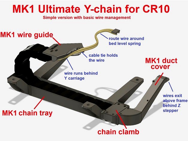
CR-10 Ultimate Y-chain MK1
Version with simple wire management
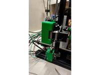
This is my solution for the Y-axis drag chain. It was design with these design idea's in mind:
Bottom mounted. No cable sticking out the back so it takes less space in a enclosure
Maximum durability. Chain must be mounted in the right way so it doesn't wear fast.
Compatible with most populair upgrades like leveling knobs and Y-stepper brackets
My 1st creation was MK1. This worked well. The simple design was effective, but i did not like the way the wires where routed. It would be very hard to remove the bed without cutting cables or a long disassembly time.
Trying to fix this made it necessary to change a lot of things in design and the way the system is mounted. I ended up with a whole new design that I called MK2. This design is very much superior in every way, and i recommend that you build MK2. It however requires a lot more parts so i published both so you can choose.
Attached drawings should give a clear image about the differences. You can find the MK2 design here: https://www.thingiverse.com/thing:2857782
PLEASE NOTE:
You will need to do some soldering. Extension cables will not work.
I recommend soldering new wires to the heatbed. You wil need a powerful soldering tool.
Higher feet are needed. I recommend these squash ball feet
This project will require you to drill a few small holes in your Y carriage.
Current version is only compatible with CR-10(S). May be compatible with Tevo Tornado
Making these mod's to your printer is at your own risk!
Parts list
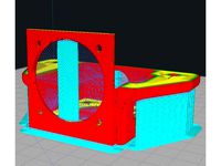
For the MK1 design you will need to print these parts:
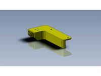
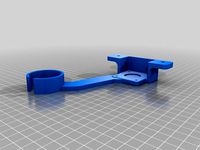
MK1 drag chain tray
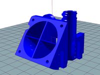
MK1 duct cover
Chain clamp
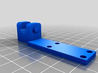
MK1 wire guide with holes, or without holes
You will also need these non printable materials
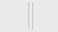
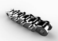
Drag chain (Please see appendix 1)
Suitable wire (Please see appendix 2)
4 pcs M5x8 bolts
4 pcs M5 V-slot nut (hammer nut)
4 pcs M3x8 bolts
3 pcs M3x12 bolts
2 pcs M3 nut
4 pcs M4x20 bolts
4 pcs M4 lock nuts (nylon)
Wire ties
Assembly instructions.
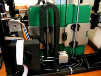
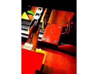
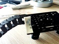
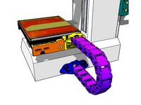
1) Start with printing and mounting some higher feet. The stock feed are approx 18mm. You will need at least 28mm (if not using cable tie), but more is better. I recommend these squash ball feet They measure approx 38mm and are great.2) Disassemble the heat bed and mark the center line on the Y carriage as illustrated in attached picture. It is very important the center line is placed accurately! If you are sure about the position, you can scratch it the lines in the coating with a sharp object.3a) If you are using the suggested drag chain (see appendix 1), print the wire guide with holes. You can use the wire guide to drill the hole pattern. Just center the wire guide and drill with a 3mm drill in the middel of the het holes.3b) If you are using a different type of drag chain, print the wire guide without holes. You will need figure out your own placement. Make sure the wire guide is centered and the chain mount is approx 1-2 mm away form the wire guide. Drill the holes in the wire guide in the same position.4) Solder the new power wires tot the bed. Point them in the opposite direction of the original position. If you do not have any experience with this, i highly recommend you read appendix 3 about soldering below. Same goes for the appendix 2 about choosing the right wire.5) Remove the thermistor wires form the original plug, and extend them with a suitable wire. Any copper stranded AW24 should be fine. You can also start the extension just below the heat bed if you feel you have the right kind of wire for the drag chain. In this case you can simply cut the wires close to the bed.6) Configure the drag chain. For the type i used (see appendix 1), i needed approx 17 links. The length can be changed at any later stage. Don't make it to short, or it will stress the chain. You only need the mounting bracket on the Y carriage. On the other end the last link is hold by a clamp.7) Mount the chain and the wire guide to the Y carriage. Make sure they stay centered and straight8) Mount the heat bed back onto the Y carriage, and route the wires around the bed leveling spring. Lay them next to each other in the wire guide, and use a wire tie to attach. Make sure the wires have plenty of room going around the spring.9) Route the wires trough the dag chain. Lay them next to each other, and do not cross or twist them!10) Mount the MK1 drag chain tray below the frame using the M5 bolts and hammer nuts. You can play a little with the position as the tray is on the large side and you correct for position by adding or removing drag chain links.The best position is with the wire dust approx 30mm behind the Z stepper11) When you are sure about the position of the tray and the right length of the drag chain, you can use the drag chain clamb and the M4 nuts and bolts, to hold the last link of the drag chain in place. Make sure the drag chain is centered and sits straight in the tray. Make sure you can move the bed without the drag chain touching any of the sides of the tray.12) Hold the wires in place so they remain uncrossed inside the drag chain. They should have plenty of room to move free within the drag chain. In the round part of the drag chain, they should not be pressed to the bottom or top of the chain. When in the right position use a cable tie to secure the wires to the tray.13) Attach the "aviation" plug to the new desired wire length. Use some braided sleeve if you want too. Attached you can find a picture of the plug if you forgot.14) Mount the MK1 duct cover to tray, and your all done!
Additional information.
Appendix 1: Drag chain type
This drag chain will need to do a lot of traveling. For this purpose i don't feel a printed drag chain is the best solution. FDM printers like the CR-10 are not accurate enough, and materials like PLA are not wear resistant enough. Best thing is to just buy this drag chain. Universal drag chains are cheap and can be found at may cheap market places like Aliexpress and Ebay.
In the attached pictures you can find all dimensions of the used drag chain. If you cant find this specific drag chain, you can look for a similar type. This type is commonly known as a 10x20 type drag chain. 10x20 is the internal dimension in mm.
Other dimensions are:
Radius: The radius to the center of the chain. In my case approx 25-26mm
Outer width: 25.7 mm, I recommend staying within 26mm to give the chain some room.
Outer thickness: Approx 12,5mm but this is mostly related to the chain height
The height is determined by the the radius and the outer thickness and can easily be calculated with: 2 x radius + thickness.
The max height for my design is 68mm
The max width is 28mm (26mm recommended)
With this knowledge you should be able to select a chain that fits. I however recommend that you buy the exact same chain as i did. Its $ 4,- and will always fit. It wil also fit the mounting holes i used in my design. Other drag chains may not.
The Aliexpress seller is SingaSong. The current link for the item is: https://nl.aliexpress.com/item/Free-Shipping-10-x-20mm-10-20mm-L1000mm-Cable-Drag-Chain-Wire-Carrier-with-end-connectors/32733132867.html
At some point i may add a printed chain to if people keep requesting it. I'm sure many existing can easily be adapted. Have you done this, pleas sent you you pictures and STL's so i can add them to this upload.
Appendix 2: Wire type
I can write a lot about this, but i'll try to stay with the basics. Your 3D printer will probably not run 24/7 for the coming 20 years. Therefore the wire does not need to be up to code, but you do need to buy a wire that is up to the task.
USING THE WRONG WIRE CAN RESULT INTO FIRE HAZARDS and can have a negative impact on the amount of heat the bed can generate.
I measured my bed at approx 0,8-0,9 ohm. At 12V the current will be approx 15A. This is in line with other specs I found online. At this "high" current level a noticeable amount of current will be dissipated in the wires meaning they will warm up. The core temperature is related to the amount of wires and the surrounding temperature. When printing ABS at a high bed temperature while in a enclosure the surrounding temperature can be quite high.
A 2,5mm2 (or AWG14) wire is rated at approx 15-20A at 30 deg C depending on regulations. The actual current the wire can carry depends on the type of insulation and ambient temperature. A 70deg C rated PVC cable at 55deg C wil be rated as low as 10A instead of 21A. A big difference. The 2,5mm2 wire now seems to thin to carry he 15A of current! On the other hand, a 6mm2 wire (AWG10) wil be very big and not very flexible enough for drag chain use.
So lets accept the wires might get a little hot, and the insulation can age fast. I think the practical maximum size is:
Metric: 2,5mm2 or 4mm2
US: AWG14 or AWG12
The used type of insulation is also very important. It needs to be flexible, and withstand high temperatures. Some types are:
PVC 70C (most common): Not great, Its flexible enough, but temperature is to low
PVC 90C: Better temperature, but usually less flexible so not great either
Silicone: Great for temperature and flexibility.
Rubber: Decent temperature and high flexibility.
Wire styles that i would recommend are SiF, SiFF and LifY. I dont know about AWM styles, but the original heat bed wire is AWM 3135. This is a silicone type and should be very suitable.
Appendix 3: Soldering on the heat bed.
The aluminium heat bed is designed to spread the heat generated by printed circuit on the back. Aluminium will conduct the heat very well so it will be hard to get enough heat onto the pads. I have a high quality 80W iron and was barely able to get enough heat in.
If you are a novice in soldering or do not have the right equipment, ask somebody else to help. De-solder the original wires first. Do not just rip them of, you could easily damage the solder pads.
Some general guidelines
Use a 80 or 100W soldering tool, and set it to the maximum heat it can candle
If available use a short and thick soldering tip to transfer the heat better
Solder with lead has a lower melting point. This may help
To little solder tin will make it hard to transfer the heat to the pads.
Take all the time you need. Don't try to rush it.
Help me improve these designs!
Please post your feedback about my designs. If you have any questions. i'll be happy to answer them, but please do read the description first.
I would love to see your makes of this!
Version with simple wire management
This is my solution for the Y-axis drag chain. It was design with these design idea's in mind:
Bottom mounted. No cable sticking out the back so it takes less space in a enclosure
Maximum durability. Chain must be mounted in the right way so it doesn't wear fast.
Compatible with most populair upgrades like leveling knobs and Y-stepper brackets
My 1st creation was MK1. This worked well. The simple design was effective, but i did not like the way the wires where routed. It would be very hard to remove the bed without cutting cables or a long disassembly time.
Trying to fix this made it necessary to change a lot of things in design and the way the system is mounted. I ended up with a whole new design that I called MK2. This design is very much superior in every way, and i recommend that you build MK2. It however requires a lot more parts so i published both so you can choose.
Attached drawings should give a clear image about the differences. You can find the MK2 design here: https://www.thingiverse.com/thing:2857782
PLEASE NOTE:
You will need to do some soldering. Extension cables will not work.
I recommend soldering new wires to the heatbed. You wil need a powerful soldering tool.
Higher feet are needed. I recommend these squash ball feet
This project will require you to drill a few small holes in your Y carriage.
Current version is only compatible with CR-10(S). May be compatible with Tevo Tornado
Making these mod's to your printer is at your own risk!
Parts list
For the MK1 design you will need to print these parts:
MK1 drag chain tray
MK1 duct cover
Chain clamp
MK1 wire guide with holes, or without holes
You will also need these non printable materials
Drag chain (Please see appendix 1)
Suitable wire (Please see appendix 2)
4 pcs M5x8 bolts
4 pcs M5 V-slot nut (hammer nut)
4 pcs M3x8 bolts
3 pcs M3x12 bolts
2 pcs M3 nut
4 pcs M4x20 bolts
4 pcs M4 lock nuts (nylon)
Wire ties
Assembly instructions.
1) Start with printing and mounting some higher feet. The stock feed are approx 18mm. You will need at least 28mm (if not using cable tie), but more is better. I recommend these squash ball feet They measure approx 38mm and are great.2) Disassemble the heat bed and mark the center line on the Y carriage as illustrated in attached picture. It is very important the center line is placed accurately! If you are sure about the position, you can scratch it the lines in the coating with a sharp object.3a) If you are using the suggested drag chain (see appendix 1), print the wire guide with holes. You can use the wire guide to drill the hole pattern. Just center the wire guide and drill with a 3mm drill in the middel of the het holes.3b) If you are using a different type of drag chain, print the wire guide without holes. You will need figure out your own placement. Make sure the wire guide is centered and the chain mount is approx 1-2 mm away form the wire guide. Drill the holes in the wire guide in the same position.4) Solder the new power wires tot the bed. Point them in the opposite direction of the original position. If you do not have any experience with this, i highly recommend you read appendix 3 about soldering below. Same goes for the appendix 2 about choosing the right wire.5) Remove the thermistor wires form the original plug, and extend them with a suitable wire. Any copper stranded AW24 should be fine. You can also start the extension just below the heat bed if you feel you have the right kind of wire for the drag chain. In this case you can simply cut the wires close to the bed.6) Configure the drag chain. For the type i used (see appendix 1), i needed approx 17 links. The length can be changed at any later stage. Don't make it to short, or it will stress the chain. You only need the mounting bracket on the Y carriage. On the other end the last link is hold by a clamp.7) Mount the chain and the wire guide to the Y carriage. Make sure they stay centered and straight8) Mount the heat bed back onto the Y carriage, and route the wires around the bed leveling spring. Lay them next to each other in the wire guide, and use a wire tie to attach. Make sure the wires have plenty of room going around the spring.9) Route the wires trough the dag chain. Lay them next to each other, and do not cross or twist them!10) Mount the MK1 drag chain tray below the frame using the M5 bolts and hammer nuts. You can play a little with the position as the tray is on the large side and you correct for position by adding or removing drag chain links.The best position is with the wire dust approx 30mm behind the Z stepper11) When you are sure about the position of the tray and the right length of the drag chain, you can use the drag chain clamb and the M4 nuts and bolts, to hold the last link of the drag chain in place. Make sure the drag chain is centered and sits straight in the tray. Make sure you can move the bed without the drag chain touching any of the sides of the tray.12) Hold the wires in place so they remain uncrossed inside the drag chain. They should have plenty of room to move free within the drag chain. In the round part of the drag chain, they should not be pressed to the bottom or top of the chain. When in the right position use a cable tie to secure the wires to the tray.13) Attach the "aviation" plug to the new desired wire length. Use some braided sleeve if you want too. Attached you can find a picture of the plug if you forgot.14) Mount the MK1 duct cover to tray, and your all done!
Additional information.
Appendix 1: Drag chain type
This drag chain will need to do a lot of traveling. For this purpose i don't feel a printed drag chain is the best solution. FDM printers like the CR-10 are not accurate enough, and materials like PLA are not wear resistant enough. Best thing is to just buy this drag chain. Universal drag chains are cheap and can be found at may cheap market places like Aliexpress and Ebay.
In the attached pictures you can find all dimensions of the used drag chain. If you cant find this specific drag chain, you can look for a similar type. This type is commonly known as a 10x20 type drag chain. 10x20 is the internal dimension in mm.
Other dimensions are:
Radius: The radius to the center of the chain. In my case approx 25-26mm
Outer width: 25.7 mm, I recommend staying within 26mm to give the chain some room.
Outer thickness: Approx 12,5mm but this is mostly related to the chain height
The height is determined by the the radius and the outer thickness and can easily be calculated with: 2 x radius + thickness.
The max height for my design is 68mm
The max width is 28mm (26mm recommended)
With this knowledge you should be able to select a chain that fits. I however recommend that you buy the exact same chain as i did. Its $ 4,- and will always fit. It wil also fit the mounting holes i used in my design. Other drag chains may not.
The Aliexpress seller is SingaSong. The current link for the item is: https://nl.aliexpress.com/item/Free-Shipping-10-x-20mm-10-20mm-L1000mm-Cable-Drag-Chain-Wire-Carrier-with-end-connectors/32733132867.html
At some point i may add a printed chain to if people keep requesting it. I'm sure many existing can easily be adapted. Have you done this, pleas sent you you pictures and STL's so i can add them to this upload.
Appendix 2: Wire type
I can write a lot about this, but i'll try to stay with the basics. Your 3D printer will probably not run 24/7 for the coming 20 years. Therefore the wire does not need to be up to code, but you do need to buy a wire that is up to the task.
USING THE WRONG WIRE CAN RESULT INTO FIRE HAZARDS and can have a negative impact on the amount of heat the bed can generate.
I measured my bed at approx 0,8-0,9 ohm. At 12V the current will be approx 15A. This is in line with other specs I found online. At this "high" current level a noticeable amount of current will be dissipated in the wires meaning they will warm up. The core temperature is related to the amount of wires and the surrounding temperature. When printing ABS at a high bed temperature while in a enclosure the surrounding temperature can be quite high.
A 2,5mm2 (or AWG14) wire is rated at approx 15-20A at 30 deg C depending on regulations. The actual current the wire can carry depends on the type of insulation and ambient temperature. A 70deg C rated PVC cable at 55deg C wil be rated as low as 10A instead of 21A. A big difference. The 2,5mm2 wire now seems to thin to carry he 15A of current! On the other hand, a 6mm2 wire (AWG10) wil be very big and not very flexible enough for drag chain use.
So lets accept the wires might get a little hot, and the insulation can age fast. I think the practical maximum size is:
Metric: 2,5mm2 or 4mm2
US: AWG14 or AWG12
The used type of insulation is also very important. It needs to be flexible, and withstand high temperatures. Some types are:
PVC 70C (most common): Not great, Its flexible enough, but temperature is to low
PVC 90C: Better temperature, but usually less flexible so not great either
Silicone: Great for temperature and flexibility.
Rubber: Decent temperature and high flexibility.
Wire styles that i would recommend are SiF, SiFF and LifY. I dont know about AWM styles, but the original heat bed wire is AWM 3135. This is a silicone type and should be very suitable.
Appendix 3: Soldering on the heat bed.
The aluminium heat bed is designed to spread the heat generated by printed circuit on the back. Aluminium will conduct the heat very well so it will be hard to get enough heat onto the pads. I have a high quality 80W iron and was barely able to get enough heat in.
If you are a novice in soldering or do not have the right equipment, ask somebody else to help. De-solder the original wires first. Do not just rip them of, you could easily damage the solder pads.
Some general guidelines
Use a 80 or 100W soldering tool, and set it to the maximum heat it can candle
If available use a short and thick soldering tip to transfer the heat better
Solder with lead has a lower melting point. This may help
To little solder tin will make it hard to transfer the heat to the pads.
Take all the time you need. Don't try to rush it.
Help me improve these designs!
Please post your feedback about my designs. If you have any questions. i'll be happy to answer them, but please do read the description first.
I would love to see your makes of this!
Similar models
thingiverse
free

CR-10 Ultimate Y-chain MK2: Y-axis drag chain for bottom mounting by superkris
...this specific drag chain, you can look for a similar type. this type is commonly known as a 10x20...
thingiverse
free

Shapeoko Drag Chain Mounts by arbus
...hatever you would like. very solid and mount to existing holes and to stepper motor bolt. no need for extra holes in the frame.
thingiverse
free
Hero Me Gen 3 with Fixed holes and shortened Wire Guide
...ain) mount made by diogosantos88. work in progress suggestions welcome.
drag chain link https://www.thingiverse.com/thing:3715002
thingiverse
free
Rigidbot heated bed energy chain mount brackets by W11cE
...l hit the case of the main board.
(i printed an extension for the chain to use less actual chain. do not be confused about this.)
thingiverse
free
Tevo Black Widow Heated Bed Cable Chain by 911ordinateur
...revent the wires for been drag by the heated bed level screws.
i also included the solidworks file if any modification is needed.
thingiverse
free
Heat Bed Cable Chain Mounts for Printrbot Simple Metal for X Axis Upgrade by Twolter66
... chain links.
i had to solder new wires onto the heat plate because they were not long enough to accommodate the length of chain.
thingiverse
free
Y-Axis Drag Chain Mounts for Wilson II by TechMav
...unts to the lower frame using one of the screws from the z-axis brace. you will need to replace the 10mm screw with a 20mm screw.
thingiverse
free
Openbuilds guide wires mounting by olo2000pm
...openbuilds guide wires mounting by olo2000pm
thingiverse
cable drag chain 10x20
guide wires
mounting
thingiverse
free
Monoprice Select Mini Heated Bed Fix Kit Complete (Chain Update) by 77-17
...type tube of 3:1 ratio preferred. wires sized appropriately similar will not get very hot in use. choice of...
grabcad
free

Modular Y-Carriage Plate for 2040V Aluminum Profile
...ter i'm building with a 350x350mm bed - needed a proper model for it so i could design a drag-chain mount for the heated bed.
Superkris
thingiverse
free
Ender 3 Ultimate Z-Box Remix of the SuperKris CR-10 Ultimate Z-Box by Chachi88
...t remixed this for the ender 3 owners, because the motor is shorter. all the other parts are the same.
thanks again, superkris.
thingiverse
free
Nespresso machine bracket for Inissia (Krups XN100) by superkris
...
if you are going to use this in your car, van, or rv i recommend to print it in petg or abs. pla can deform easily in a hot car.
thingiverse
free
CR-10 Double X Stepper Damper w/ Fan Mount by ketchu13
...original model "cr-10 double x stepper damper bracket" by superkris remixed to include a 40x40 fan...
thingiverse
free
CR-10 Double X stepper damper bracket by superkris
... the design. i used dampers i bought on aliexpress. seller name is funssor. these are approx 6mm thick excluding the center ring.
thingiverse
free
CR-10 Z damper and Mosaic Scroll Wheel Mount Combo by mediaman
...scroll wheel mount combo by mediaman thingiverse thanks to superkris and ido3dprintz. this is a remix to get both...
thingiverse
free
Creality CR-10/Tevo Tornado 2nd X Stepper Mount for Double Dampers by Mk42Workshop
...vibration damping, without flex. this is a remix of superkris#39;s excellent design. he was nice enough to add the...
thingiverse
free
CR-10 Ultimate Y-chain MK2: Y-axis drag chain for bottom mounting by superkris
...ny questions. i'll be happy to answer them, but please do read the description first.
i would love to see your makes of this!
thingiverse
free
CR-10 Mini Double X stepper damper brace by Shiver999
...thingiverse this is a remix of the bracket from superkris i modified the bracket that allows the motor to...
thingiverse
free
CR-10 Ultimate Z-Box: The ideal drag chain + X-axis stepper damper bracket + wire management solution by superkris
...guess these could work with a little modification
i will not be advising you on how to implement the sensor output on your cr-10.
Mk1
turbosquid
$25

Cutlass MK1
...urbosquid
royalty free 3d model cutlass mk1 for download as on turbosquid: 3d models for games, architecture, videos. (1387253)
turbosquid
free
Lewis mk1
...s mk1
turbosquid
free 3d model lewis mk1 for download as fbx on turbosquid: 3d models for games, architecture, videos. (1614469)
3d_export
$5

Escort MK1
...escort mk1
3dexport
turbosquid
$14
Table Mk1
... available on turbo squid, the world's leading provider of digital 3d models for visualization, films, television, and games.
turbosquid
$10
Stove Mk1
... available on turbo squid, the world's leading provider of digital 3d models for visualization, films, television, and games.
3d_export
$99

Maserati 3500GT mk1
...maserati 3500gt mk1
3dexport
turbosquid
free

VW Golf MK1
...osquid
free 3d model vw golf mk1 for download as c4d and obj on turbosquid: 3d models for games, architecture, videos. (1707225)
turbosquid
$100

Hawker Fury MK1
... available on turbo squid, the world's leading provider of digital 3d models for visualization, films, television, and games.
turbosquid
$100

Hawker Fury MK1
... available on turbo squid, the world's leading provider of digital 3d models for visualization, films, television, and games.
turbosquid
$100

Hawker Fury MK1
... available on turbo squid, the world's leading provider of digital 3d models for visualization, films, television, and games.
Drag
turbosquid
$30
Drag Pack Centerline Auto Drag Wheels
... available on turbo squid, the world's leading provider of digital 3d models for visualization, films, television, and games.
turbosquid
$30

Drag Pack Centerline Auto Drag Wheels
... available on turbo squid, the world's leading provider of digital 3d models for visualization, films, television, and games.
turbosquid
$5

Drag Car
...r
turbosquid
royalty free 3d model drag car for download as on turbosquid: 3d models for games, architecture, videos. (1613195)
turbosquid
free

drag strip
...free 3d model drag strip for download as fbx and unitypackage on turbosquid: 3d models for games, architecture, videos. (1486232)
turbosquid
$8

drag bike.max
... available on turbo squid, the world's leading provider of digital 3d models for visualization, films, television, and games.
turbosquid
$49

Raven drag red
...uid
royalty free 3d model raven drag red for download as fbx on turbosquid: 3d models for games, architecture, videos. (1486830)
turbosquid
$199

Pro Stock Drag Car
...y free 3d model pro stock drag car for download as ma and obj on turbosquid: 3d models for games, architecture, videos. (1341240)
turbosquid
$38

BFGoodrich Auto Drag Combo
...l bfgoodrich auto drag combo for download as ma, obj, and fbx on turbosquid: 3d models for games, architecture, videos. (1457166)
turbosquid
$199

Funny Car Drag Car
... available on turbo squid, the world's leading provider of digital 3d models for visualization, films, television, and games.
turbosquid
$20
Centerline Auto Drag Wheels
... available on turbo squid, the world's leading provider of digital 3d models for visualization, films, television, and games.
Ultimate
turbosquid
$3
Ultimate Grave
...model ultimate grave for download as blend, obj, stl, and fbx on turbosquid: 3d models for games, architecture, videos. (1636144)
turbosquid
$79

ULTIMATE GIRAFFE
... available on turbo squid, the world's leading provider of digital 3d models for visualization, films, television, and games.
turbosquid
$5
The Ultimate Bowl
... available on turbo squid, the world's leading provider of digital 3d models for visualization, films, television, and games.
turbosquid
$1

Ultimate Revolver
... available on turbo squid, the world's leading provider of digital 3d models for visualization, films, television, and games.
3ddd
$1

Kimera Ultimate DVD System
...kimera ultimate dvd system
3ddd
dvd
schneider kimera ultimate dvd system
cg_studio
$49

The Ultimate Lioness3d model
... model
cgstudio
.max .obj .fbx - the ultimate lioness 3d model, royalty free license available, instant download after purchase.
turbosquid
$5
Ultimate Brick Castle
...yalty free 3d model ultimate brick castle for download as fbx on turbosquid: 3d models for games, architecture, videos. (1335247)
turbosquid
$31

Zombie Ultimate pack
... available on turbo squid, the world's leading provider of digital 3d models for visualization, films, television, and games.
turbosquid
$8
Barrels Ultimate Pack
...ls ultimate pack for download as ma, max, obj, fbx, and blend on turbosquid: 3d models for games, architecture, videos. (1353281)
turbosquid
$25

Ultimate "F" Bomb
... available on turbo squid, the world's leading provider of digital 3d models for visualization, films, television, and games.
Cr
turbosquid
$15
Creazioni CR-673 CR-4461
... available on turbo squid, the world's leading provider of digital 3d models for visualization, films, television, and games.
3ddd
$1
Ravak CR 055.00
...ravak cr 055.00
3ddd
ravak , смеситель
ravak cr 055.00
turbosquid
$100
CR-002
...
turbosquid
royalty free 3d model cr-002 for download as stl on turbosquid: 3d models for games, architecture, videos. (1686037)
3ddd
$1

Ravak CR 012.00
...ravak cr 012.00
3ddd
ravak , смеситель
смеситель ravak cr 012.00
3ddd
free
Консоль CR Currin
...ь , cr currin
консоль cr currin
ширина - 1675 мм
глубина - 510 мм
общая высота - 810 мм
3ddd
$1
CR 39444
...0
диаметр: 100
тип патрона: gu5,3 gu10
количество ламп: 1
мощность: 35w
цвет: золото хрусталь
материал: металл хрусталь exclusive
3d_ocean
$89

Honda CR-Z
...www.youtube.com/watch?v=rrbb4d4lypk ` he honda cr-z‘s exterior styling is formed around a “one-motion wedge” concept with a lo...
3ddd
$1

Creazoni / STEFY CR-8901
...creazoni / stefy cr-8901
3ddd
creazoni
creazioni stefy cr-8901
turbosquid
$60

Chain-CR-001
...squid
royalty free 3d model chain-cr-001 for download as stl on turbosquid: 3d models for games, architecture, videos. (1680536)
turbosquid
$99

Honda CR-Z
... available on turbo squid, the world's leading provider of digital 3d models for visualization, films, television, and games.
Axis
3ddd
$1

Мария Axis
...
3ddd
кухня , классическая , axis
модель кухни.
3d_export
$22
Axis robot 6-axis robotic arm
...ing parts drawings, standard parts purchased parts list, can be produced directly according to the drawings, welcome to download!
3ddd
free

Versatile Axis
...ddd
nexus , плитка
http://bvtileandstone.com/ceramic-porcelain/versatile-axis/
3d_export
$19
robot 2 axis
...robot 2 axis
3dexport
robot 2 axis
turbosquid
$40
Axis R5F
... available on turbo squid, the world's leading provider of digital 3d models for visualization, films, television, and games.
turbosquid
$40
Axis S5F
... available on turbo squid, the world's leading provider of digital 3d models for visualization, films, television, and games.
turbosquid
$30

Axis Athlon
... available on turbo squid, the world's leading provider of digital 3d models for visualization, films, television, and games.
turbosquid
$10

Linear Axis
... available on turbo squid, the world's leading provider of digital 3d models for visualization, films, television, and games.
3d_export
$15

drawing axis
...drawing axis
3dexport
simple rendering of the scene file
3ddd
$1
versatile axis ARC
...versatile axis arc
3ddd
versatile , плитка
versatile axis arc red dot design award
Chain
archibase_planet
free
Chain
...chain
archibase planet
chain chain link chain loop
chain n020708 - 3d model (*.gsm+*.3ds) for interior 3d visualization.
3d_export
$5
chain
...chain
3dexport
3d model chain
3d_export
$5
chain
...chain
3dexport
chain. obj,fbx,blend
archibase_planet
free

Chain
...se planet
chain circuit catena
chain - archicad parametrical gdl 3d model (*.gsm). regulation of the length, curvature and angle.
archibase_planet
free
Chain
...n
archibase planet
chain circuit catena
chain - archicad parametrical gdl 3d model(*.gsm). regulation of the length and angle xyz
3d_ocean
$5
Chain
...chain
3docean
3d models chain design elements
3d models, design elements
3d_ocean
$5

Chain
...chain
3docean
3d models chain design elements
3d models, design elements
turbosquid
$10
Chain
...hain
turbosquid
royalty free 3d model chain for download as on turbosquid: 3d models for games, architecture, videos. (1329200)
turbosquid
$9
chain
...hain
turbosquid
royalty free 3d model chain for download as on turbosquid: 3d models for games, architecture, videos. (1549461)
turbosquid
$2
Chain
...hain
turbosquid
royalty free 3d model chain for download as on turbosquid: 3d models for games, architecture, videos. (1148668)
Bottom
turbosquid
$6
Wooden Bottom
...3d model wooden bottom for download as dae, fbx, obj, and stl on turbosquid: 3d models for games, architecture, videos. (1631844)
turbosquid
$40

Bottom Quark
... available on turbo squid, the world's leading provider of digital 3d models for visualization, films, television, and games.
turbosquid
$18
Bottom Fish
...del bottom fish for download as 3ds, fbx, blend, dae, and stl on turbosquid: 3d models for games, architecture, videos. (1400208)
turbosquid
$15
Pillar Bottom
... available on turbo squid, the world's leading provider of digital 3d models for visualization, films, television, and games.
turbosquid
$8
Pumpkin, Flat Bottom
...oyalty free 3d model pumpkin, flat bottom for download as stl on turbosquid: 3d models for games, architecture, videos. (1348299)
turbosquid
$8
Pumpkin, Flat Bottom
...oyalty free 3d model pumpkin, flat bottom for download as stl on turbosquid: 3d models for games, architecture, videos. (1348289)
turbosquid
$45
Fancy flared bottom
...free 3d model fancy flared bottom for download as max and pac on turbosquid: 3d models for games, architecture, videos. (1471223)
turbosquid
$9
Bottom Bouncer and Worm
... available on turbo squid, the world's leading provider of digital 3d models for visualization, films, television, and games.
3d_export
$10
Tank Top Bottoms 3D Model
...tank top bottoms 3d model
3dexport
tank top bottoms
tank top bottoms 3d model bkl1989 63245 3dexport
cg_studio
$69

The bottom of the lake scene3d model
...3d model
cgstudio
.max - the bottom of the lake scene 3d model, royalty free license available, instant download after purchase.
Y
turbosquid
$1

Tetera y Galletas y Caf
... available on turbo squid, the world's leading provider of digital 3d models for visualization, films, television, and games.
3ddd
$1

Смеситель Y-CON
...смеситель y-con
3ddd
смеситель , y-con
смеситель y-con
3ddd
$1
Y-Chair
...y-chair
3ddd
tom dixon
y-chair designed by tom dixon,
3ds max + obj, corona
3ddd
$1
Y Chair compilation
....net/products/us/y-chair-sled-base
y chair swivel basehttp://www.tomdixon.net/products/us/y-chair-swivel-base
turbosquid
$190
Y-8
...y-8
turbosquid
royalty free 3d model y-8 for download as max on turbosquid: 3d models for games, architecture, videos. (1658891)
turbosquid
$7
Bench Y
...turbosquid
royalty free 3d model bench y for download as obj on turbosquid: 3d models for games, architecture, videos. (1488746)
turbosquid
$15

bonePile Y
...oyalty free 3d model bonepile y for download as blend and obj on turbosquid: 3d models for games, architecture, videos. (1546374)
turbosquid
$7

Y for Yarn
...d
royalty free 3d model y for yarn model for download as max on turbosquid: 3d models for games, architecture, videos. (1699732)
turbosquid
$2
FONT Y
...quid
royalty free 3d model font y for download as ma and obj on turbosquid: 3d models for games, architecture, videos. (1549457)
3ddd
$1

WOOD-y
...wood-y
3ddd
wooden guy
10
turbosquid
$25

10
... available on turbo squid, the world's leading provider of digital 3d models for visualization, films, television, and games.
turbosquid
$10
a-10
... available on turbo squid, the world's leading provider of digital 3d models for visualization, films, television, and games.
3ddd
$1

EX 10
...ex 10
3ddd
samsung , фотоаппарат
ex 10
3ddd
$1

Bed 10
...bed 10
3ddd
постельное белье
bed 10
evermotion
$25

Scene 10 Archinteriors vol. 10
...dering design interior
take a look at textured and shadered visualization scene ready to be rendered.. evermotion 3d models shop.
3ddd
$1
Curtains 10
...curtains 10
3ddd
curtains 10
3ds max 2011,fbx + textures
polys: 100355
3ddd
free

PLANTS 10
...plants 10
3ddd
цветок , горшок
plants 10,, with 3 different color planter boxes
turbosquid
$24

Chandelier MD 89310-10+10 Osgona
... chandelier md 89310-10+10 osgona for download as max and fbx on turbosquid: 3d models for games, architecture, videos. (1218762)
design_connected
$29
Nuvola 10
...nuvola 10
designconnected
gervasoni nuvola 10 computer generated 3d model. designed by navone, paola.
design_connected
$22

Kilt 10
...kilt 10
designconnected
zanotta kilt 10 computer generated 3d model. designed by progetti, emaf.
Mounting
3d_export
free

mounting bracket
...mounting plate is the portion of a hinge that attaches to the wood. mounting plates can be used indoors, cabinetry and furniture.
turbosquid
$2

MOUNTING
... available on turbo squid, the world's leading provider of digital 3d models for visualization, films, television, and games.
turbosquid
free

Mounts
... available on turbo squid, the world's leading provider of digital 3d models for visualization, films, television, and games.
turbosquid
free

Mount Fuji
...fuji
turbosquid
free 3d model mount fuji for download as obj on turbosquid: 3d models for games, architecture, videos. (1579977)
3d_export
$5

Headphone mount LR
...headphone mount lr
3dexport
headphone mount l+r
turbosquid
$39

Mount rainier
...quid
royalty free 3d model mount rainier for download as fbx on turbosquid: 3d models for games, architecture, videos. (1492586)
turbosquid
$5

pipe mounting
...quid
royalty free 3d model pipe mounting for download as obj on turbosquid: 3d models for games, architecture, videos. (1293744)
turbosquid
$3

Mounting Tires
...uid
royalty free 3d model mounting tires for download as fbx on turbosquid: 3d models for games, architecture, videos. (1708511)
3d_export
$5

Magnetic GoPro Mount
...pro mount
3dexport
cool magnetic mount for gopro. allows you to mount the camera on flat metal surfaces and get exclusive shots.
turbosquid
$5

Stone Mount
...ty free 3d model stone mount for download as ma, obj, and fbx on turbosquid: 3d models for games, architecture, videos. (1370306)