Thingiverse
Counterflow Air to Air Heat Exchange by pheolix
by Thingiverse
Last crawled date: 3 years ago
This is an initial design for a printable parametrised counterflow air to air heat exchange (HX).
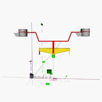
Typically counterflow HXs use 2 sets of interleaved plates, with the supply air flowing through one set and the extract air flowing through the other set. Heat is transferred from the extract air to the incoming, thereby keeping the heat in the building while replacing the air. In this design rather than using a set of parallel plates the airflows have been mingled together by creating a component that guides the airflows into a set of rectangular channels.
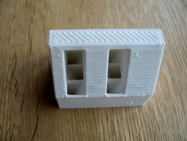
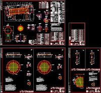
The printed version shown only has three parts of the HX included, otherwise only the slots at the top and bottom are visible which makes it difficult to explain how it works. In the printed object the bottom section is a regular grid with airflow in one direction surrounded on four sides by airflow going in the opposite direction, this is the heat transfer part of the heat exchange. To speed-up debugging I have made this section quite short but the length, width, height and channel layout are defined as arguments to an openscad module HX. The middle part of the component guides the air from separate channels into a set of parallel paths and then the top bit carries the air to different sides of the heat exchange, one for supply and the other for extract. The middle bit and top bit need to be replicated onto the bottom of the heat exchange to multiplex/demultiplex on that end.
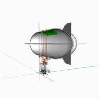
A small version and a more usable version are shown with the bottom of the HX in place. Outside air enters the right side of the upper triangle, warms up as it passes through the heat exchange and comes out of the left side of the bottom triangle then enters the building. Air extracted from the building enters the right side of the bottom triangle, goes up through the HX and transfers its heat to the incoming air, exits the upper triangle on the left side.
The design is parameterised so the number of channels in the HX array can be set and these values ripple through the other components.
This is an experiment to help understand the shape of the airmixer above the HX array. I think the next thing to do is to break this into components so that I can experiment with different lengths and materials for the HX array, either printed or commodity extruded profile. To assess the HX efficiency it will need a work harness, I'm thinking of a couple of muffin fans, an insulated enclosure, ideally mated to 100mm ducting and a microcontroller for instrumentation and fan control.
Typically counterflow HXs use 2 sets of interleaved plates, with the supply air flowing through one set and the extract air flowing through the other set. Heat is transferred from the extract air to the incoming, thereby keeping the heat in the building while replacing the air. In this design rather than using a set of parallel plates the airflows have been mingled together by creating a component that guides the airflows into a set of rectangular channels.
The printed version shown only has three parts of the HX included, otherwise only the slots at the top and bottom are visible which makes it difficult to explain how it works. In the printed object the bottom section is a regular grid with airflow in one direction surrounded on four sides by airflow going in the opposite direction, this is the heat transfer part of the heat exchange. To speed-up debugging I have made this section quite short but the length, width, height and channel layout are defined as arguments to an openscad module HX. The middle part of the component guides the air from separate channels into a set of parallel paths and then the top bit carries the air to different sides of the heat exchange, one for supply and the other for extract. The middle bit and top bit need to be replicated onto the bottom of the heat exchange to multiplex/demultiplex on that end.
A small version and a more usable version are shown with the bottom of the HX in place. Outside air enters the right side of the upper triangle, warms up as it passes through the heat exchange and comes out of the left side of the bottom triangle then enters the building. Air extracted from the building enters the right side of the bottom triangle, goes up through the HX and transfers its heat to the incoming air, exits the upper triangle on the left side.
The design is parameterised so the number of channels in the HX array can be set and these values ripple through the other components.
This is an experiment to help understand the shape of the airmixer above the HX array. I think the next thing to do is to break this into components so that I can experiment with different lengths and materials for the HX array, either printed or commodity extruded profile. To assess the HX efficiency it will need a work harness, I'm thinking of a couple of muffin fans, an insulated enclosure, ideally mated to 100mm ducting and a microcontroller for instrumentation and fan control.
Similar models
grabcad
free

Heat Exchanger
...hanger that transfers the heat generated by an electronic or a mechanical device to a fluid medium, often air or a liquid coolant
grabcad
free

heat exchanger
... as engine coolant flows through radiator coils and air flows past the coils, which cools the coolant and heats the incoming air.
grabcad
free

Heat Exchanger flow simulation
...rabcad
this is a mini project of heat transfer between two fluids water and air . this is like shell & tube heat exchanger .
grabcad
free

flow heat air exchanger
...flow heat air exchanger
grabcad
flow heat air exchanger
grabcad
free

CFD Analysis of Shell and Tube Heat Exchanger
...rovides valuable insights into the performance of the heat exchanger and can be used to improve its efficiency and effectiveness.
grabcad
free

Shell & Tube Heat Exchanger
...es, while the other fluid flows around the tubes in the shell. heat is transferred between the two fluids through the tube walls.
grabcad
free

air condtioned heat exchanger
...ondenser, the refrigerant flows into the heat exchanger and transfers heat, either gaining or releasing it to the cooling medium.
grabcad
free

Shell & Tube Heat Exchanger
...exchanger designs. one fluids runs through the tubes, and another fluid flows over the tubes to transfer heat between two fluids.
3dwarehouse
free

Chillus Convolutus Counterflow Wort Chiller
...chillus convolutus counterflow wort chiller
3dwarehouse
a counterflow heat exchanger made of copper and used in homebrewing.
grabcad
free

Shell and tube heat exchanger
...ansfer heat between the two fluids, one fluid flows through the tubes and another fluid flows over the tubes (through the shell).
Counterflow
turbosquid
$6

CounterFlow
... available on turbo squid, the world's leading provider of digital 3d models for visualization, films, television, and games.
thingiverse
free
Grainfather Chiller Mount by mBoughen75
...mount by mboughen75 thingiverse brackets for supporting the grainfather counterflow chiller mounted horizontally on a brew stand. i've used...
thingiverse
free
PCVI by DrRoesch_ETH
...pcvi by drroesch_eth thingiverse this is the pumped counterflow virtual impactor (pcvi). it has the slanted inlet and...
cg_trader
$4

CounterFlow
...iled enough for close-up renders. originally modelled in 3ds max 2014.
final images rendered with stand alone standard renderer.
grabcad
free

ALUMINIUM COUNTERFLOW HEAT EXCHANGER
...aluminium counterflow heat exchanger
grabcad
for educational purposes
grabcad
free

Counterflow Chiller Frame
...5 x 12mm will work too)
rubber feet (tripod feet, furniture feet, etc) with 1/4" or 6mm threads, .75" max thread length
grabcad
free

Cooling tower
...climate cooling. it works on on the principle of counterflow water flows down while the air is pulled upwards...
grabcad
free

ПОУМ-3000
...heating and subsequent cooling of milk in a four-piece, counterflow plate heat...
3dwarehouse
free
Chillus Convolutus Counterflow Wort Chiller
...chillus convolutus counterflow wort chiller
3dwarehouse
a counterflow heat exchanger made of copper and used in homebrewing.
Exchange
3d_export
$25
heat exchanger
...heat exchanger
3dexport
mid cylinder for main process fluid flow. outer & center cylinder is for coolant flow.
3d_export
$12
33m3 tubular heat exchanger diagram
...33m3 tubular heat exchanger diagram
3dexport
33m3 tubular heat exchanger diagram
3d_export
$6
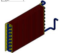
Plate Fin Heat Exchanger Design
...plate fin heat exchanger design
3dexport
plate fin heat exchanger design
3d_export
$19
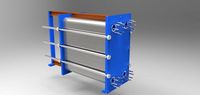
Plate Heat Exchanger 3D Model
...plate heat exchanger 3d model
3dexport
plate heat exchanger 3d model zarko 72409 3dexport
turbosquid
$9

DaTa eXchange black coin
...ty free 3d model data exchange black coin for download as max on turbosquid: 3d models for games, architecture, videos. (1495575)
turbosquid
$9

DaTa eXchange gold coin
...lty free 3d model data exchange gold coin for download as max on turbosquid: 3d models for games, architecture, videos. (1495569)
turbosquid
$9

nash exchange black coin
...ty free 3d model nash exchange black coin for download as max on turbosquid: 3d models for games, architecture, videos. (1458312)
turbosquid
$9

nash exchange gold coin
...lty free 3d model nash exchange gold coin for download as max on turbosquid: 3d models for games, architecture, videos. (1458311)
turbosquid
$29

Stock Exchange Office | CITID
... available on turbo squid, the world's leading provider of digital 3d models for visualization, films, television, and games.
3d_export
$25
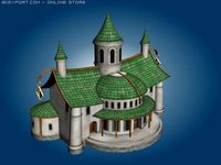
Fantasy Exchange 3D Model
...ented concocted fairy-tale fabulous fantastic improbable model stylish conceptual
fantasy exchange 3d model budulaj 7288 3dexport
Heat
3d_export
$5
heat
...heat
3dexport
heat tool
3ddd
$1
electric heating
...electric heating
3ddd
обогреватель
electric heating
3d_export
$6
The heating module
...any questions also you can email to me. designed with solidworks 2017, render with keyshot **************************************
turbosquid
free
Heating Rod
...rod
turbosquid
free 3d model heating rod for download as obj on turbosquid: 3d models for games, architecture, videos. (1482690)
turbosquid
$2
Heating Radiator
...
royalty free 3d model heating radiator for download as blend on turbosquid: 3d models for games, architecture, videos. (1561908)
3d_export
$35
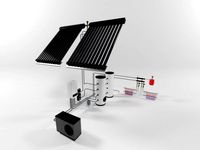
heating instalation with heat pump and solar system
...el , please contact me. before buying a model, you can try to download one of my free models and testing. thank you for watching.
turbosquid
$29
Heating Mantle
... available on turbo squid, the world's leading provider of digital 3d models for visualization, films, television, and games.
turbosquid
$25
Heating Radiator
... available on turbo squid, the world's leading provider of digital 3d models for visualization, films, television, and games.
turbosquid
$20
AT_airship_control_stand_(heated)
... available on turbo squid, the world's leading provider of digital 3d models for visualization, films, television, and games.
turbosquid
$20
AT_airship_(heated)
... available on turbo squid, the world's leading provider of digital 3d models for visualization, films, television, and games.
Air
3ddd
$1
Calligaris air
...calligaris air
3ddd
air , calligaris
cтул calligaris air
3ddd
$1

Air freshener
...air freshener
3ddd
air freshener , освежитель
air freshener
design_connected
$16

Air
...air
designconnected
flexform air lounge chairs computer generated 3d model. designed by antonio citterio.
turbosquid
$250
Heat pump air air
... available on turbo squid, the world's leading provider of digital 3d models for visualization, films, television, and games.
3d_export
$5
air
...air
3dexport
3ddd
$1
Кухня AIR
...кухня air
3ddd
air , мария
кухня air фабрики "мария"
3ddd
$1
Лампа AIR
...лампа air
3ddd
boconcept , air
настольная лампа air, boconcept. в50½xø32см
3d_export
$40
air deflector
...air deflector
3dexport
air deflector
3d_export
$15

air purifier
...air purifier
3dexport
air purifier
3d_export
$5

macbook air
...macbook air
3dexport
macbook air