Thingiverse
Continuity tester model and upgrade by makibox850
by Thingiverse
Last crawled date: 3 years ago
The thing:
No bird house, no Saturn V rocket. Just a handy tool.
Make something good even better.
Have recently set the focus on the blue newer version (V2).
The grey older version (V1) can be changed for using nowadays batteries as well.
See below.
This is a versatile electro installation-/ car- /motorcycle- /bicycle- continuity tester.
Production started 1956. Over the time many improved releases were issued.
Production has ended 1990.
Still sold by western profit makers after they had shot down my country and grabbed for pennies the good things we made.
TODO:
-make a new electronics assembly
-revise the top cone design, thread has not been perfectly centered (Tinkercad fail)
Why is that?
When Tinkercad aligns two selected shapes it uses a few outer edges or points on the perimeter for reference.
This does not work on threads or similar non uniformly shaped objects.
Even on triangles andhexagonal nuts the alignment depends on the relative orientation, mainly the hight of the top over the base.
It should use the centerline of the objects or the midpoint it had started when making using a script at least on demand. I.e. thread generator script.
They should fix it a.s.a.p.
But no.
It has many flaws , same with Thingiverse.
They are still messing with everytime changed website layout and laggy servers, it happens for years makes it worse each time they put theyr hands on.
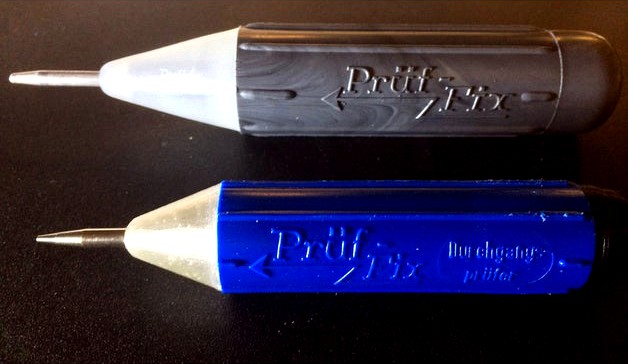
The candidates:
-tester V1 (grey) just the battery and a green(white) indicator soffitte lamp (2.5Volts)
-tester V2 (blue)
Tester V2 has a piezo buzzer and a 5mm red LED built in.
The top part of tester V2 seems to be friction welded onto the handle/battery compartment part 2. I could not pry it open without damaging the "electronics".
Update:
Made the new top cone for the blue Prueffix V2 tester
Made the thread at the cut open top of the handle.
Cut it open using a hack saw the bue tester lost its cone now.
The assembly can be used together with the ATTiny tester electronics.
Good. It needs just a little rewiring.
Modify them for using modern types of batteries.
The older grey tester (V1)
A little longer spring allows running grey tester (overvolted) from a single 18650 battery instead of EOL 2R10 (type 8) at 3 volts. Put resistor or two diodes in series to bring the voltage down.
The newer tester (V2)
New circuitry or just the adapter thing filling the empty space allows running the blue tester from a single 3 volts battery (123A) instead of two AA each at 1.5 volts.
For the "electronics" modification
Parts used:
as of the schematics from technoblogy
ATTiny 85 ,I will try to fit the 8 PDIP chip
capacitor foil 0.1uF
resistor 2.7kOhm
resistor 51 Ohm
LED 3mm/5mm red or green
small piezzo buzzer
For the stock tiny 10mm buzzer (polarized! with integrated driver) I had to put a resistor of 180 Ohm in series.
Otherwise it would not beep or start oscillating permanently.
For buzzers with own drivers the code could be changed.
It works even with just pulling the pin 3 "High" for the intended duration of beeping.
No PWM is neded.
Software
-ATTiny code http://www.technoblogy.com/list?1ZNS
-files from Technoblogy (compressed ZIP-file)
-Arduino IDE supplemental files
ATTiny Core files https://github.com/SpenceKonde/ATTinyCore
No bird house, no Saturn V rocket. Just a handy tool.
Make something good even better.
Have recently set the focus on the blue newer version (V2).
The grey older version (V1) can be changed for using nowadays batteries as well.
See below.
This is a versatile electro installation-/ car- /motorcycle- /bicycle- continuity tester.
Production started 1956. Over the time many improved releases were issued.
Production has ended 1990.
Still sold by western profit makers after they had shot down my country and grabbed for pennies the good things we made.
TODO:
-make a new electronics assembly
-revise the top cone design, thread has not been perfectly centered (Tinkercad fail)
Why is that?
When Tinkercad aligns two selected shapes it uses a few outer edges or points on the perimeter for reference.
This does not work on threads or similar non uniformly shaped objects.
Even on triangles andhexagonal nuts the alignment depends on the relative orientation, mainly the hight of the top over the base.
It should use the centerline of the objects or the midpoint it had started when making using a script at least on demand. I.e. thread generator script.
They should fix it a.s.a.p.
But no.
It has many flaws , same with Thingiverse.
They are still messing with everytime changed website layout and laggy servers, it happens for years makes it worse each time they put theyr hands on.
The candidates:
-tester V1 (grey) just the battery and a green(white) indicator soffitte lamp (2.5Volts)
-tester V2 (blue)
Tester V2 has a piezo buzzer and a 5mm red LED built in.
The top part of tester V2 seems to be friction welded onto the handle/battery compartment part 2. I could not pry it open without damaging the "electronics".
Update:
Made the new top cone for the blue Prueffix V2 tester
Made the thread at the cut open top of the handle.
Cut it open using a hack saw the bue tester lost its cone now.
The assembly can be used together with the ATTiny tester electronics.
Good. It needs just a little rewiring.
Modify them for using modern types of batteries.
The older grey tester (V1)
A little longer spring allows running grey tester (overvolted) from a single 18650 battery instead of EOL 2R10 (type 8) at 3 volts. Put resistor or two diodes in series to bring the voltage down.
The newer tester (V2)
New circuitry or just the adapter thing filling the empty space allows running the blue tester from a single 3 volts battery (123A) instead of two AA each at 1.5 volts.
For the "electronics" modification
Parts used:
as of the schematics from technoblogy
ATTiny 85 ,I will try to fit the 8 PDIP chip
capacitor foil 0.1uF
resistor 2.7kOhm
resistor 51 Ohm
LED 3mm/5mm red or green
small piezzo buzzer
For the stock tiny 10mm buzzer (polarized! with integrated driver) I had to put a resistor of 180 Ohm in series.
Otherwise it would not beep or start oscillating permanently.
For buzzers with own drivers the code could be changed.
It works even with just pulling the pin 3 "High" for the intended duration of beeping.
No PWM is neded.
Software
-ATTiny code http://www.technoblogy.com/list?1ZNS
-files from Technoblogy (compressed ZIP-file)
-Arduino IDE supplemental files
ATTiny Core files https://github.com/SpenceKonde/ATTinyCore
Similar models
thingiverse
free

ZB2L3 Case - 18650 Battery Capacity Tester Housing by ahmeted
...res support.
parts: (affiliate links)
zb2l3 battery capacity tester: banggood
18650 battery box: banggood
x4 m3x6 screw: banggood
3dwarehouse
free

220 ohm resistor
...220 ohm resistor
3dwarehouse
4 band 220 ohm resistor 6mm #4_band #carbon #electronic #resistor
thingiverse
free

Battery Voltage Tester by DaveGun
... by zip ties to a tube
handle on the motorcycle. pressing the button on the top of the case
displays the voltage of the battery.
3dwarehouse
free

RES-561 (560 ohm resistor)
...resistor part of a collection of useful electronic components note: scaled 100 times (because sketchup is funny at smaller sizes)
thingiverse
free

Dummy load Case by powercam
...ube.com/watch?v=4n_jccbwj0q
replace resistor by 2k ohm (1k ohm x2)
puzzle cut library from http://www.thingiverse.com/thing:35834
3dwarehouse
free

Button Cell Battery CR2025 3 Volt
...attery used by small electronic circuits. the battery has an output of 3 volts #3_volts #3v #3volts #battery #button_cell #cr2025
grabcad
free

BEEP
...beep
grabcad
beep,buzzer
grabcad
free

Enclosure for Digital electronic part tester PCB
...tester pcb
grabcad
the casing or box for digital transistor, diode, resistor, capacitor meter. the battery is placed out of box.
thingiverse
free

LED Circuit Board Class Activity by robertvarney1
...tor (yellow,violet,brown)
-9 volt battery
-9 volt battery connector (with stripped positive and negative leads)
-conductive paint
3dwarehouse
free

RES-222 (2.2 k ohm Resistor)
...resistor part of a collection of useful electronic components note: scaled 100 times (because sketchup is funny at smaller sizes)
Makibox850
thingiverse
free

Messbuchsenfassung by makibox850
...unting of metal sockets for banana plugs onto panels.
the banana sockets have 3.6mm holes, 7mm collar on the opening, 6mm thread.
thingiverse
free

x-axis adjustment helper by makibox850
...iverse
this things helps for adjusting the y-axis to be square with the x-axis on the k8200/3drag.
take this at your own risk.
thingiverse
free

CTC keypad support by makibox850
...the pads upright more so they do not get stuck when they were pressed at an angle.
it replaces the big amount of washers as well.
thingiverse
free

Cameo2 pen holder adapter (refresh) by makibox850
...om/thing:3776350
cameo2 penholder, type of stabilo pen 88
changes made
-smoother shape
-less space between the pen and the walls.
thingiverse
free

IC Pinausrichter Kombo by makibox850
...ken können pins im abstand von 15mm gerichtet werden.
in dieser zusammenstellung noch nicht gedruckt.
sollte aber funktionieren.
thingiverse
free

Shuttle barebon psu coverplate by makibox850
...
having the stock psu removed this thing holds the fan and the powerinlet of a replacement high efficiency passivly cooled psu.
thingiverse
free

frame 4mm with slot for slides 60x100x2mm by makibox850
... films, photos, pcb,…
use it alone or combined with other parts from my modular box systemhttp://www.thingiverse.com/thing:506288
thingiverse
free

backplate for Wanhao Duplicator i3 (remixed from jamesarm97) by makibox850
...e fans only.
added some kind of standoffs for the bigger screws.
removed the beveled openings.
files:
with standoffs
no standoffs
thingiverse
free

keyring bottle opener by makibox850
...://www.tinkercad.com/things/cjsg16g1vlv-keyring-bottle-opener-redrawn-and-improved
update:
second file now with the keyring hole.
thingiverse
free

Apple wireless keyboard dish 3D model by makibox850
...keyboard riser for apple wireless keyboard model a1314.
eventually i have scaled the thing up by adding 1mm in x and y direction.
Tester
turbosquid
$2

tester
... available on turbo squid, the world's leading provider of digital 3d models for visualization, films, television, and games.
turbosquid
$24
Hipot Tester
...odel hipot tester for download as skp, 3ds, dae, fbx, and obj on turbosquid: 3d models for games, architecture, videos. (1651595)
turbosquid
$10

Tester Cube
... available on turbo squid, the world's leading provider of digital 3d models for visualization, films, television, and games.
turbosquid
free

BIPED tester
... available on turbo squid, the world's leading provider of digital 3d models for visualization, films, television, and games.
turbosquid
$30
99 Tester SM
...e 3d model 99 tester sm for download as ma, max, obj, and fbx on turbosquid: 3d models for games, architecture, videos. (1258979)
turbosquid
$15

AC Electric Tester 2
...ectric tester 2 for download as max, ige, obj, stl, and sldpr on turbosquid: 3d models for games, architecture, videos. (1464810)
turbosquid
$14

Digital Electric Tester Pen
...tric tester pen for download as max, ige, obj, stl, and sldpr on turbosquid: 3d models for games, architecture, videos. (1416100)
3d_export
$15
Probe Screwdriver 3D Model
...screw driver voltage volt electronic equipment tool electric contact tester detector flat head electrician electrical probe screwdriver 3d model...
3ddd
$1

Тестер стенд Jane Iredale, наборы теней Beauties Factory
...iredale, beauties factory страна изготовитель: сша, гонконг англ. описание: testerstend jane iredale, sets of shadows beauties factory 120 and...
3d_export
$18

an automatic line for fct function test of pcb
...and lift pcb boards at both ends of the tester after the test is ok, the product flows out...
Upgrade
turbosquid
$15
Upgraded Glock
...e 3d model upgraded glock for download as obj, fbx, and blend on turbosquid: 3d models for games, architecture, videos. (1185950)
3ddd
$1

Calligaris / UPGRADE
...calligaris / upgrade
3ddd
calligaris
c материалом
3d_export
free
cz upgrade
...cz upgrade
3dexport
https://www.buymeacoffee.com/mestrezen3d https://linktr.ee/mestrezen3
turbosquid
$80

Custer Tank upgrade
... available on turbo squid, the world's leading provider of digital 3d models for visualization, films, television, and games.
turbosquid
$39

Domestos 1 upgrade
... available on turbo squid, the world's leading provider of digital 3d models for visualization, films, television, and games.
3d_export
$10

Upgraded tea cup
...upgraded tea cup
3dexport
a cup with an unusual design and a unique shape for a more enjoyable tea experience
3d_export
$8

dixy outlander classic style upgraded poplar wood lounge chair
...utlander classic style upgraded poplar wood lounge chair
3dexport
dixy outlander classic style upgraded poplar wood lounge chair
turbosquid
free

AK-12 + Upgrades low-poly 3D model
...ow-poly 3d model for download as fbx, blend, and unitypackage on turbosquid: 3d models for games, architecture, videos. (1501145)
evermotion
$700

Upgrade from V-ray 1.5 to 3.5 for 3ds max
...here is no need to purchase a new dongle - your current dongles will be reprogrammed to carry v-ray 3. evermotion 3d models shop.
evermotion
$300

Upgrade from V-Ray 2.0 to V-ray 3.5 for 3ds Max
... interface (gui) for editing settings on one machine and one render node for rendering on one machine. evermotion 3d models shop.
Continuity
3ddd
free

Bush continuation
...bush continuation
3ddd
куст
continuation of various forms of a bush
turbosquid
$1

Continue Pipe
...yalty free 3d model continue pipe for download as c4d and fbx on turbosquid: 3d models for games, architecture, videos. (1294580)
turbosquid
$24

Continuous tracks
... 3d model continuous tracks for download as 3ds, obj, and c4d on turbosquid: 3d models for games, architecture, videos. (1390710)
turbosquid
free

Continuous Tracks
... available on turbo squid, the world's leading provider of digital 3d models for visualization, films, television, and games.
cg_studio
$70

Continuous Miner3d model
...udio
.fbx .stl .obj .dwg .dxf .max - continuous miner 3d model, royalty free license available, instant download after purchase.
3d_export
$18

large mansion-continuous gate 32
...large mansion-continuous gate 32
3dexport
large mansion-continuous gate 32<br>3ds max 2015
turbosquid
free

Six-star geometry with G2 continuity
... available on turbo squid, the world's leading provider of digital 3d models for visualization, films, television, and games.
cg_studio
$50

CVT - Small continuously variable transmission3d model
... .obj - cvt - small continuously variable transmission 3d model, royalty free license available, instant download after purchase.
3d_export
$16

BENTLEY BLOWER CONTINUATION 1929
...im birkin’s 1929 supercharged 4½-litre “blower” modeled with improved surface meshing to make the model as compact as reasonable.
turbosquid
$49

SiberStove Superpower Portable Wood-Burning Continuous Heating Stove Cherry
... available on turbo squid, the world's leading provider of digital 3d models for visualization, films, television, and games.