GrabCAD

Constant Mesh Gear box - Transmission demonstration of 1:1 and 2:1
by GrabCAD
Last crawled date: 1 year, 11 months ago
This was completed as part of a university assignment in my final year of Electronic and Computer Systems Engineering at Victoria University of Wellington.
The brief was that within an enclosure space of maximum dimension 150 mm on each side we needed to show a functioning gearing system. The motor/shaft/bearings were provided from Servo City.
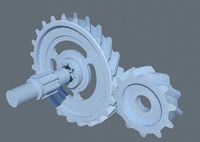
Following the following guide, we created bevel gears to shift the input through 90 degrees, onto a driven shaft with a fixed rotation velocity of 30 rpm.
https://www.youtube.com/watch?v=NwWi_WDGcTU#t=1116.945997
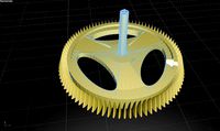
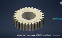
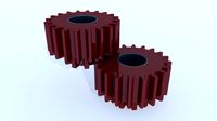
Then, to simulate a gear box, we used a variety of equation driven involute gears, helpfully described by this guide:
https://grabcad.com/tutorials/tutorial-how-to-model-involute-gears-in-solidworks-and-show-design-intent and further information from the Dudley Book of Gears.
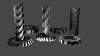
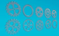
In the exploded gear view image in the gallery it is possible to grasp how this system functions as a constant mesh gearbox.
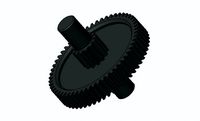
Red gears are used for driving the output shaft. The middle collar is used to mesh the gear to the output shaft, or shift the system into idle where the output shaft will not be driven.
Green gears are the slave gears, and have a 1:1 or 2:1 gearing ratio respectively. These will be in constant motion as they are driven by the Blue gears, providing power to the system from the motor input.
In practice switching gears functioned well but was not the smoothest operation as there is no functioning cone system to bring the synchronised gear up to speed from idle.
The brief was that within an enclosure space of maximum dimension 150 mm on each side we needed to show a functioning gearing system. The motor/shaft/bearings were provided from Servo City.
Following the following guide, we created bevel gears to shift the input through 90 degrees, onto a driven shaft with a fixed rotation velocity of 30 rpm.
https://www.youtube.com/watch?v=NwWi_WDGcTU#t=1116.945997
Then, to simulate a gear box, we used a variety of equation driven involute gears, helpfully described by this guide:
https://grabcad.com/tutorials/tutorial-how-to-model-involute-gears-in-solidworks-and-show-design-intent and further information from the Dudley Book of Gears.
In the exploded gear view image in the gallery it is possible to grasp how this system functions as a constant mesh gearbox.
Red gears are used for driving the output shaft. The middle collar is used to mesh the gear to the output shaft, or shift the system into idle where the output shaft will not be driven.
Green gears are the slave gears, and have a 1:1 or 2:1 gearing ratio respectively. These will be in constant motion as they are driven by the Blue gears, providing power to the system from the motor input.
In practice switching gears functioned well but was not the smoothest operation as there is no functioning cone system to bring the synchronised gear up to speed from idle.
Similar models
grabcad
free

Involute Gear Design from Scratch
... tutorial is located here:
http://grabcad.com/questions/tutorial-how-to-model-involute-gears-in-solidworks-and-show-design-intent
grabcad
free

Involute gear wheel
...nvolute gear wheel. it is used to transfer power from one shaft to another. it is connected to the driver shaft and driven shaft.
grabcad
free

Animated. Spur Gears and Idler Gear System.
...e output gear by being between the input and the output.
idle gears do not affect the speed ratio of the driver and driven gears.
grabcad
free

Gear Reducer
... of gears and their relative sizes, a gear reducer can change the direction of rotation from the input shaft to the output shaft.
thingiverse
free

Variable to Constant Gearbox Prototype by MkMan
...s with tachometers, recording the results at varying speeds and comparing the observed results with the theoretical calculations.
grabcad
free

gear speed enhancer
...gear speed enhancer
grabcad
with the help of gear system, speed of the output shaft is 3 times more than that of input shaft.
grabcad
free

Compound Planetary Gearbox
...ut together differently in order for them to mesh correctly with the second ring gear.
please don't forget to 'like'!
grabcad
free

Gear box
...en the input and output shafts. gearboxes are commonly used in automobiles, industrial machinery, and power transmission systems.
grabcad
free

Reduction Gear
... gear train, and transmits power through to the output or driven gear.
this reduction gear is able to provide two speed outputs.
grabcad
free

gear system
...tem
grabcad
a gear system with a single input and multiple rotational and translational outputs. made for a university project.
Constant
3ddd
$1

Edelform - CONSTANTE / Константе
...константе
3ddd
edelform , constante
edelform - серия constante / константе. вся линейка.
turbosquid
$9

Constant black coin
...royalty free 3d model constant black coin for download as max on turbosquid: 3d models for games, architecture, videos. (1495033)
turbosquid
$9

Constant gold coin
...
royalty free 3d model constant gold coin for download as max on turbosquid: 3d models for games, architecture, videos. (1495014)
3d_ocean
$1

Constant resistor
...an. if you need something like this, please, check out my other items or buy a whole pack of all electrical parts that i made....
3d_export
$10

Compressor Dalgakiran flow rate 45m3 per minute
...rate 45m3 per minute 3dexport compressor dalgakiran, with a constant air capacity of 45m3 per...
3d_export
$50
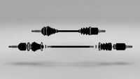
Exploded Half Axle 3D Model
...3dexport cv joint axle shaft drive gearbox wheel velocity constant engine chassis part planetary exploded half axle 3d model...
3d_export
free

Dam on the river
...waterworks on the river. a dam that maintains a constant level in the lake. 3d model is made using...
3d_export
free

couch
...obj.<br>textures 2048x2048 png: basecolor and normal<br>no rouchness map, use constant ...
3d_export
$5

bunk bed
...2048 x 2048 png: basecolor and normal. please use constant 1 for...
3d_ocean
$9

Half Axle
...half axle 3docean axle chassis constant cv drive engine gearbox joint part planetary shaft velocity...
Demonstration
3d_export
$5

Solitaire Ring Demonstration 3D Model
...solitaire ring demonstration 3d model
3dexport
solitaire ring demonstration 3d model rehansheikh 30601 3dexport
3d_export
$9

Simple atmosphere fashion demonstration area SU model
...simple atmosphere fashion demonstration area su model
3dexport
simple atmosphere + fashion demonstration area su modelv
3d_export
$19

Enterotoxin demonstration internal organs anatomy gastrointestinal
...ation internal organs anatomy gastrointestinal, human organs medical animation black intestine stomach 2.files include 3dmax mb
3d_export
$7

Characteristic Chinese-style demonstration area landscape su model
... chinese-style demonstration area landscape su model
3dexport
characteristic chinese-style demonstration area landscape su model
3d_export
$5

robot cat
...cat 3dexport 3d model of a robot cat for demonstration or...
3d_export
$299

dragon
...animation. the scene and video file are attached for demonstration ...
3d_export
$5

vertu new signature touch
...vertu new signature touch 3dexport vertu phone for demonstration purposes, assistance in creating a picture or...
3d_ocean
$30

Realistic Lens For Camera
...outside buttons and displays. perfect for mechanism of lens demonstration all parts were made with...
3d_export
$10

Toaster 3D Model
...toaster 3d model
3dexport
toaster house-hold kitchen electronics appliances
toaster 3d model demonstrator 32412 3dexport
3d_ocean
$2

Loudspeaker
...loudspeaker 3docean demonstration loudspeaker music police speaker tool voice a high-quality model...
Transmission
3d_export
$5
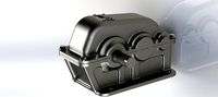
transmission gearbox
...transmission gearbox
3dexport
transmission gearbox
archibase_planet
free
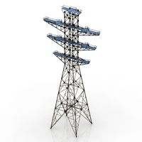
Transmission tower
...lectricity pylon lattice tower framework tower
transmission tower n121015 - 3d model (*.gsm+*.3ds) for exterior 3d visualization.
turbosquid
$5

Lasvit TRANSMISSION
... available on turbo squid, the world's leading provider of digital 3d models for visualization, films, television, and games.
design_connected
$13

Transmission Sculpture Chandelier
...ture chandelier
designconnected
lasvit transmission sculpture chandelier computer generated 3d model. designed by studio deform.
turbosquid
$25

TRANSMISSION FULL OUTOMATIC
...ee 3d model transmission full outomatic for download as sldas on turbosquid: 3d models for games, architecture, videos. (1331288)
archive3d
free

Transmission tower 3D Model
...mework tower
transmission tower n121015 - 3d model (*.gsm+*.3ds) for exterior 3d visualization.
3d_export
free

tinket planetary transmission
...tinket planetary transmission
3dexport
3ddd
$1

Lasvit Transmission Торшер
...ry angle. glass parts are joined by heat, creating individual elements that become one material and one body.
приятных рендеров)
3ddd
$1

Lasvit Transmission люстры
...ry angle. glass parts are joined by heat, creating individual elements that become one material and one body.
приятных рендеров)
turbosquid
$15

Electrical transmission tower
... available on turbo squid, the world's leading provider of digital 3d models for visualization, films, television, and games.
Gear
3d_ocean
$4
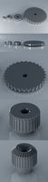
Gears
...gears
3docean
gear gears iron
4 different size of gears
3d_export
$5
gear
...gear
3dexport
gear
3d_export
free
Gears
...gears
3dexport
gears
3d_export
$5
gear
...gear
3dexport
a simple model of gear
3d_export
$5
gear
...gear
3dexport
gear for transmission , case machine
3d_ocean
$3
Gears
...nical parts process steampunk vehicle wheel work
10 different gear models volume 01-10 files: .3ds .c4d .obj note: you need vray
3d_ocean
$1

Spur Gear
...spur gear
3docean
decoration gear
a typical spur gear
3d_ocean
$4
Gear wheels
...gear wheels
3docean
engine engineering gear gears industry machinery mechanical toothwheel wheel
pair of gear wheels : animated.
turbosquid
$9
Gear
...gear
turbosquid
royalty free 3d model gear for download as on turbosquid: 3d models for games, architecture, videos. (1712328)
turbosquid
$2
Gears
...rs
turbosquid
royalty free 3d model gears for download as ma on turbosquid: 3d models for games, architecture, videos. (1166710)
Mesh
design_connected
$16

Mesh
...mesh
designconnected
jaipur living mesh computer generated 3d model.
design_connected
$13

Mesh
...mesh
designconnected
luceplan mesh computer generated 3d model. designed by gomez paz, francisco.
turbosquid
$29
mesh
...lty free 3d model mesh for download as 3ds, obj, c4d, and fbx on turbosquid: 3d models for games, architecture, videos. (1361487)
turbosquid
$1
mesh
... available on turbo squid, the world's leading provider of digital 3d models for visualization, films, television, and games.
3d_export
$5
mesh fence
...mesh fence
3dexport
metal mesh fence
3d_export
$5
hexagonal mesh
...hexagonal mesh
3dexport
3d model of hexagoal mesh
3d_export
$5
shelf mesh
...shelf mesh
3dexport
shelf mesh kare design
3ddd
free
mesh chair
...mesh chair
3ddd
стул
оффисное кресло mesh chair
3d_ocean
$8
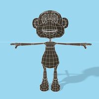
Monkey mesh
...monkey mesh
3docean
animal hand monkey shoes tail
this is a low poly mesh of a cartoon monkey mesh. i hope you enjoy this model.
3d_ocean
$2
Wire mesh
...sire aspect. the model has materials applied and is ready to render in both formats(obj/blend). the mesh can be cut or expande...
Box
archibase_planet
free
Box
...box
archibase planet
box carton cardboard box
box 2 - 3d model (*.3ds) for interior 3d visualization.
archibase_planet
free
Box
...box
archibase planet
carton cardboard box box
box 1 - 3d model (*.3ds) for interior 3d visualization.
3d_export
$6
box
...box
3dexport
box
3d_export
$5
Box
...box
3dexport
box
3d_export
$5
box
...box
3dexport
box
3d_export
$5
box
...box
3dexport
box
archibase_planet
free

Box
...box
archibase planet
box box for paper notebook pencil
box - 3d model (*.gsm+*.3ds) for interior 3d visualization.
archibase_planet
free
Box
...box
archibase planet
box carton cardboard box
box n170111 - 3d model (*.gsm+*.3ds) for interior 3d visualization.
archibase_planet
free
Box
...box
archibase planet
box carton cardboard box
box n050411 - 3d model (*.gsm+*.3ds) for interior 3d visualization.
archibase_planet
free

Boxes
...boxes
archibase planet
boxes box case bin
boxes n281213 - 3d model (*.gsm+*.3ds+*.max) for interior 3d visualization.
1
turbosquid
$69
armchairs(1)(1)
... available on turbo squid, the world's leading provider of digital 3d models for visualization, films, television, and games.
turbosquid
$15
ring 1+1
... available on turbo squid, the world's leading provider of digital 3d models for visualization, films, television, and games.
turbosquid
$10
chair(1)(1)
... available on turbo squid, the world's leading provider of digital 3d models for visualization, films, television, and games.
turbosquid
$8

Chair(1)(1)
... available on turbo squid, the world's leading provider of digital 3d models for visualization, films, television, and games.
turbosquid
$2

RING 1(1)
... available on turbo squid, the world's leading provider of digital 3d models for visualization, films, television, and games.
turbosquid
$1
house 1(1)
... available on turbo squid, the world's leading provider of digital 3d models for visualization, films, television, and games.
turbosquid
$1
Table 1(1)
... available on turbo squid, the world's leading provider of digital 3d models for visualization, films, television, and games.
turbosquid
$59
Formula 1(1)
...lty free 3d model formula 1 for download as max, fbx, and obj on turbosquid: 3d models for games, architecture, videos. (1567088)
design_connected
$11
No 1
...no 1
designconnected
sibast no 1 computer generated 3d model. designed by sibast, helge.
turbosquid
$2
desert house(1)(1)
...3d model desert house(1)(1) for download as 3ds, max, and obj on turbosquid: 3d models for games, architecture, videos. (1055095)
2
design_connected
$11
No 2
...no 2
designconnected
sibast no 2 computer generated 3d model. designed by sibast, helge.
turbosquid
$6
Cliff Rock 2-2
...uid
royalty free 3d model cliff rock 2-2 for download as obj on turbosquid: 3d models for games, architecture, videos. (1619161)
turbosquid
$29

Book variation 2 2
...3d model book variation 2 2 for download as max, obj, and fbx on turbosquid: 3d models for games, architecture, videos. (1366868)
turbosquid
$22
Classic baluster (2) (2)
...assic baluster (2) (2) for download as max, obj, fbx, and stl on turbosquid: 3d models for games, architecture, videos. (1483789)
turbosquid
$99

Smilodon 2 Pose 2
... available on turbo squid, the world's leading provider of digital 3d models for visualization, films, television, and games.
turbosquid
$20
Barrel Barricade 2-2
... available on turbo squid, the world's leading provider of digital 3d models for visualization, films, television, and games.
turbosquid
$6
Wall Trophy (2) (2)
... available on turbo squid, the world's leading provider of digital 3d models for visualization, films, television, and games.
turbosquid
free
Tire label 2 of 2
... available on turbo squid, the world's leading provider of digital 3d models for visualization, films, television, and games.
3ddd
$1

Кровать, 2 тумбочки, 2 светильника
...кровать, 2 тумбочки, 2 светильника
3ddd
кровать, 2 тумбочки, 2 светильника
нормальное качество
формат 3ds max
без текстур
3ddd
free
Кровать, 2 тумбочки, 2 светильника
...кровать, 2 тумбочки, 2 светильника
3ddd
кровать, 2 тумбочки, 2 светильника
нормальное качество
формат 3ds max
без текстур