Thingiverse
CONCEPTUAL DESIGN OF A SUSTAINABLE BUILDING SELF by Isarts3d
by Thingiverse
Last crawled date: 2 years, 11 months ago
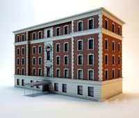
CONCEPTUAL DESIGN OF A SUSTAINABLE BUILDING SELF
Initially the idea was to create a design theme based pollution , ie , a way to reduce it atravéz a simple and self-sufficient system.
Except that throughout the development of the project , this was taken other forms, fleeing the main focus .
Thought in a tower that would suck the polluted air , passing through a scrubber system and being released clean.
This tower would have a utility , s why it occurred to me to create a simple building , whose roof provide electricity through photovoltaic cells . It could be a public building , such as a gas service to the population , in any activity .
Only to produce a good amount of power , would have a considerable area , s why I created three separate floors each other , with their own coverage .
Adopt the round shape, where the whole set would rely on a central structure .
I thought you might also enjoy the heat warm the floor, and after trying several ideas , eventually resulting in a metal trough , which divide coverage into four parts , and form a frame around this , besides facilitating the install mode of cell plates solar power plants , which produce electricity.
This metal trough , solar heated, lead removed from the air indoors to the top of the building where there was a generator .
To accommodate this system , created a dome in the building .
It occurred to me that I could take this hot air coming out of the pipe on the roof , and then created a cubicle in a part of the dome , which concentrated heat there would warm a spiral pipe for water heating .
The ideas were emerging. Could benefit the entire area of coverage to collect rainwater , leading it into underground reservoirs , which contribute much of that used in the network economy.
And to save even more water , installed a system to reuse water from kitchen sinks and bathroom and showers , if any, to recliclagem in the building itself, whose system is located underground. This recycled water would be reused in the use of toilet flushing .
For completeness, it occurred to me to install a system of natural air cooling . Then , in the basement , installed a centrifugal pump . She would suck air from the garage, go through a filtering system that would purify the air , which would be driven to an air tank , located just below the basement , dividing the reservoir of rainwater and drinking water . This air tank , in contact with cold water from two reservoirs , resfriaria the air from the pump , and hence would be conducted through the pipe , also think of it in contact with water , and then follow the environments .
In this way would form a cycle . The air inside the pavements would be sucked into the system composed of the metal rails heated by the sun , and this coming moving upward , the trigger generator that produces electricity , which is tapped by the electric motor driving a centrifugal pump , which purifies and cools leading to the air indoors.
From the foregoing , it seems simple and practical. The building would be self sufficient in electricity because theoretically produce more than consumption , and make a huge saving of water , contributing greatly to the preservation of the environment . After all, the electricity comes from hydropower most of which do not always realize the demand , in addition to the construction of them affects the environment and drinking water is increasingly scarce .
Remains to be seen if the whole system really works ! After all , this thermal hot air circulation system in motion , produced by temperature differences , which would be capable of producing electricity , not seen implemented in any building or something.
Theoretically it should work , because the wind is so produced in nature , with the displacement of cold air to the hot regions . To prove if this application exist in practice , I found on the internet that there are solar chimneys that produce electricity using this principle . So I think that should work in my project .
After all , it is a conceptual design where ideas are conceived and designed in drawings then go through a verification of its feasibility .
Also , the idea of natural cooling of the air as it passes through the tank and piping provided with water , is something to see in practice.
At the most , there is no doubt that the energy produced by photovoltaic cells installed on the roof of the floor , with a large area , since each floor has its own , is in itself sufficient to meet the demand of the building , because the technology in this field is well advanced .
I am not an architect or engineer , nor have any college. The ideas come , and I will freely drawing like this building , which has no structural calculation , and therefore nothing was scaled , and thus do not have any idea for example, how many watts of electricity can be produced , nor how much water Rainwater may be collected .
Also in the matter of design , should be well short of qualified professionals , beyond what I was adding things as the ideas were emerging . For that reason they , nor I think this building has its own style . But the main objective of this conceptual design is the application of systems that aims at sustainability , in making it self-sustainable in energy and water saving big .
After the 3D design , produce the maximum possible images for better understanding of the project , with images of the building both external and internal , and detailing in plan views and sections , and a didactic explanation of each system.
Main Building - The main features of this building , provided self-sustaining , it fit the requirements with regard to energy and water savings , and contribute to the preservation of the environment .
He contributes to the environment, as it produces its own electricity , as this contributes to dependence on energy from hydropower , which cause much trouble with their buildings in forested areas . And the water in the world becomes increasingly scarce , hence the importance of saving as much as possible , atravéz the use of rainwater and recycling .
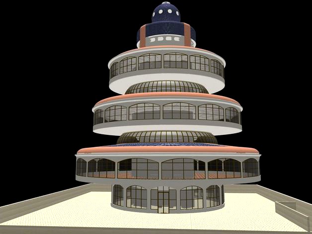
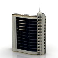
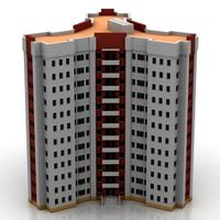
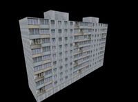
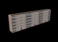
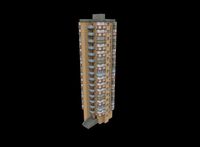
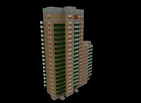
Architecture Building - The building of circular shape , has 5 floors : basement, ground floor , and another three floors. In addition, at the top, there is a machine house , and above it , the water tank, and lastly , the dome , where the generator and hot air cell is located.
Also has elevator and fire escape .
There is also an empty area , a moat that surrounds the main structure , which provides lighting and ventilation to the area inside the building.
The skylight surrounding the entry of light and ventilation of the ditch on the decks 1 and 2 , in addition to protecting this entry , must have frames that allow the entry of air for ventilation .
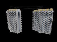
It has a good picture of the building in general, atravéz images 1-9 , extract images in which perspectives of the building , at various positions on the outside , and some internal .
The sectional views and perspectives of the building , the images10 , 11 and 12 give more clarity to the understanding of the project as it indicates all the details of their internal and external characteristics , revealing the ladder of fire , elevators , lighting and ventilation gap , natural lighting , and other items .
For better utilization of incidence of the sun on the roofs of the building , designed the first floor with greater area , gradually decreasing to the second floor and the third smallest area , culminating with the extension of the water tower and dome . Furthermore, there is a machine room , which abrigga the elevator motor .
Downstairs, in the outer area can be landscaped part , and another part for parking , which is not set .
INCLUDED IN SYSTEMS DESIGN BUILDING self-sustaining
6 are systems that will raise the building to be included in the list of those who give importance to sustainability.
Among these , some unpublished , as the production of electricity by thermal system , that is, through the displacement of hot air produced by metal rails , and that drive a generator , natural lighting inside the ambientese , in addition to luminaires using electricity , and natural air cooling , atravéz this passage in a tank that is in contact with water . In other systems , already used, what differentiates them are the projects .
Listed below is a description of these 6 systems :
1 - NATURAL LIGHTING - order maximum use of natural lighting , all floors have glazed frames , providing good lighting during the day . And to further leverage natural lighting , the project also includes these items :
Intended for lighting and ventilation of the inner side of all floors of the building environments - empty around the building structure ( Image14 ) downtown area. See details in the image - 14 .
Daylighting of floors 2 and 3 ( Image16 ) - This is achieved via the pipes that distribute the decks 1 and 2 , and that capture the light from the roof and falls directly on decks , illuminating them internally.
For greater use of natural light from this source , a specific project is needed in order to enhance the brightness .
Can be achieved via paint with reflective material inside the ducts , or use of mirrors at certain angles in order to conduct the light directly to the environments .
With these measures , the illumination provided by glazed sashes to circumvents all floors , the introduction of natural light environments in the inside of the building , it must provide at least a 50 % brightness during the day .
The rest is complemented atravéz fixtures , most existing economic market , with energy produced by the building itself . This makes it completely self-sufficient in this requirement.
2 - SYSTEMS ELECTRIC POWER PRODUCTIONS
There are two systems that produce electricity designed this building ( Image15 ) :
2.1 system with photovoltaic solar panels and flexible plate - Harnessing the luminosity of the sun - Installed on roofs floors, including the dome , producing electricity to meet the demand of the building , lighting and operation of equipment .
Due to the circular shape of the coverage of floors, there must be a combination of photovoltaic panels , which are rectangular , with flexible solar panels , which will finish on the uneven parts .
Have rooftop tanks and the dome , which are too curvelíneos , surely everyone should be flexible solar panels .
With the spread of this energy production system with photovoltaic cells , there is no doubt as to their potential for production of electricity, especially in this project, where their characteristics , there is a large area where these plates and panels will be installed .
The excess energy can be stored in batteries that can be located in the engine room and the basement . This stored energy can be used at night .
2.2 System of thermal energy ( image17 ) - Harnessing the sun's heat , the heat can also be used to produce electricity , atravéz heating the air, that this condition becomes lighter , and then is pushed by air cooler, and thus produces movement, atravéz this displacement .
In this project, there are metal rails that are distributed on the floor coverings , forming a frame on the outside , and a collar around the main structure , as shown in the image18 .
These frames find themselves interconnected , then head for pipe embedded in the pillar of the building structure , up to the upper reservoir of water until convergence in a cubicle that compresses the air before they get to the generator .
The operation of the system takes atravéz heating the metal rails , the sun , and thus also heats the air inside them .
O, lighter warm air rises , pushed by cooler air from the indoor collected by nozzles that are initiated in the lining as shown in image17 . This displacement of air through the gutters , through the pipes , with the right speed , enable the generation of electricity.
There are two ways through which this displacement of air from the floor .
The first are the rails of the deck 1 and 2, which are concentrated in four outings and follow the pillar to the embedded product , continue through the reservoir top water and end in a cubicle at the bottom of the dome , as shown in the image18 .
The second are the gutters pavimento3 . The air follows a different path of the two lower decks . Trough pavimento3 coverage , which focuses on four outings pursuing above , from the outside of the engine room , water reservoir to the base of the dome , where a collar that surrounds this base , and the four ducts converging chute air into the cubicle , so the convergence of the tubes of the floors 1 and 2, as shown in image18 .
With the concentration of air from these eight sources in this cubicle , a certain pressure , which will help increase the speed of displacement of the air in the top of the cubicle outlet tube, thus moving the blades of the generator occurs , the point of producing electricity as seen in the image 17 e18 .
The energy generated can be utilized in the operation of equipment , and even stored in batteries .
With these two systems in operation , the production of electricity is more than enough to meet the demands of the building , there will be even surpluses that can be placed on the public network .
Taking into account that on weekends and holidays , although there are no hours these days , however the production of electricity not to . What do you do with this excess electricity ? The obvious solution is to play in public , and may even generate profits .
3 - SYSTEM OF EXPLOITATION OF STORMWATER ( image19 , 22 ) -
The same way that the characteristics of the project , with decks with their own coverage provides a large area for the production of electricity, this area also favors gathering at greater amount of rainwater that is collected by the edges of the channel cover , and then enter the pipe embedded in the pillar and down to the floor structure of the floor , reaching the reservoir underground.
The upper floors 2 and 3, the collected rainwater is channeled to all four pillars embedded in the tubes , and fall down to the ground , where they are forwarded to the inspection , which pass through a filter to trap impurities , and hence drop box directly into the stormwater reservoir , located in the basement below the garage.
There are two reservoirs , opposite each other , one side of the building, and another on the other side .
In pavimento1 , which has larger area , collected water will follow another way. After passing the first pillar of the pavement , through the structure of the floor to give ground on the pillar , and hence also goes to the inspection box , lying to water with the other floors .
Rainwater stored in underground reservoirs , are conducted through the pump to the upper reservoir , above the engine room , and then are distributed at points of use of the building .
This water can be used in toilets toilets , for washing floors and watering plants in gardens . Filtered may be used in the kitchen.
4 - SYSTEM OF PRODUCTION OF HOT WATER ( Image20 )
The hot air from the production of thermal energy , which would be thrown out , can be used to heat water .
This procedure is done as follows . The water in the upper reservoir is sucked by a pump located beside the electric generator , above the upper reservoir , and then driven up to the cubicle hot air , where the pipe assumes a spiral shape around the inside of the cubicle in full contact with hot air, thereby heating the water. This hot water is returned to the reservoir for it. The cycle repeats , with the pump sucking the water in the pipes that pass through the cubicle hot air , and returns to the hot water tank . Thus, the water that warms up the tank maximum temperature obtained , ready for use in the kitchen or bathroom.
This saves money on heating water with electric utility power , or gas.
The electric pump uses the energy produced by the building itself .
This system helps to save gas and energy in heating water used in baths and also in the kitchen .
5 - COOLING SYSTEM NATURAL AIR ( Image21 )
They usually have to leave the air -conditioned room with a comfortable temperature, well below the temperature of the summer, it's hot.
I present this project a different cool air alternative. Out instead of using air conditioning, the suggestion is to cool the air naturally.
In this system , the air sucked into the garage by means of a centrifugal pump is directed to a reservoir tank installed between the rainwater and drinking water.
The idea is that the tank in contact with the cold water naturally cool the air contained therein , and thus led to the upper floors will help to cool the atmosphere .
Besides the air tank in contact with the water pipe coming out of it passes through the water tank , also contributing to cool the air passing inside.
Filtering the air at the base which supports the centrífica pump , the air pushed by the centrifugal pump passes through an air filter box , to then proceed to the air tank in the ground below. Thus , in addition to the fresh air that reaches the environments , this will also be clean of pollution typical of large cities.
The image21 shows in detail the installation of this system with centrifugal pump installed in the basement garage , the air tank installed below between Pluvia water reservoirs and drinking water, as well as the pipe coming out of it in contact with water and then heading to the upper floors .
The power to drive the motor centrifugal pump that can be generated by thermal system whose energy produced atravéz Hot air can be used .
The hot air on metal gutters causes movement of air sucked into the internal environments , which drives the generator , producing electricity. This energy is used to move the motor centrifugal pump that moves the cooled air in the tanks located in the water supply , and hence , for the following environments . This forms a natural cycle . The ambient air is continually renewed . Thus , in this process , the external hot air itself helps to cool the indoor air environments .
6 - WATER SYSTEM recycled in ( Image22 )
The proveneninte the sinks of the bathrooms and kitchen , and bath water can be treated through a cleaning process , and thus repurposed for use in the discharge of toilets .
As shown in the image22 , the dirty water is conveyed to a tank in the basement below the basement garage . Passes through a filter tank and then to the other tank side. This water is conducted through a pump to the upper reservoir above the engine room . Hence , it is distributed in the bathrooms of the building .
Do not go into detail on the hydraulic design of this facility, which is on account of designers who specialize in the area . They also compete to design a calculated according to the systems currently used .
This procedure will greatly contribute in saving water , which becomes increasingly scarce in the major cities .
To complete , if possible, also the toilets dirty water could go through a cleaning process before being thrown into the sewer . This would contribute much to relieve the city's treatment plants .
This project , by its characteristics, could be used in halls of small towns , the big cities or boroughs . These would give an excellent example of sustainability , very recurrent theme nowadays.
Also medium businesses can use this architecture in their corporate HQ . In some shops this model may be appropriate .
If this system for buildings , with these characteristics of sustainability is widely used , including residential buildings , will surely give a great contribution to the conservation of the environment , since it will prevent construction of hydroelectric and thermoelectric power in developing countries , who still prefer electricity generated by these systems than the currently most modern , which is the energy produced by wind turbines and photovoltaics .
Translate this text with google translator , s why some words can exit out of context.
Initially the idea was to create a design theme based pollution , ie , a way to reduce it atravéz a simple and self-sufficient system.
Except that throughout the development of the project , this was taken other forms, fleeing the main focus .
Thought in a tower that would suck the polluted air , passing through a scrubber system and being released clean.
This tower would have a utility , s why it occurred to me to create a simple building , whose roof provide electricity through photovoltaic cells . It could be a public building , such as a gas service to the population , in any activity .
Only to produce a good amount of power , would have a considerable area , s why I created three separate floors each other , with their own coverage .
Adopt the round shape, where the whole set would rely on a central structure .
I thought you might also enjoy the heat warm the floor, and after trying several ideas , eventually resulting in a metal trough , which divide coverage into four parts , and form a frame around this , besides facilitating the install mode of cell plates solar power plants , which produce electricity.
This metal trough , solar heated, lead removed from the air indoors to the top of the building where there was a generator .
To accommodate this system , created a dome in the building .
It occurred to me that I could take this hot air coming out of the pipe on the roof , and then created a cubicle in a part of the dome , which concentrated heat there would warm a spiral pipe for water heating .
The ideas were emerging. Could benefit the entire area of coverage to collect rainwater , leading it into underground reservoirs , which contribute much of that used in the network economy.
And to save even more water , installed a system to reuse water from kitchen sinks and bathroom and showers , if any, to recliclagem in the building itself, whose system is located underground. This recycled water would be reused in the use of toilet flushing .
For completeness, it occurred to me to install a system of natural air cooling . Then , in the basement , installed a centrifugal pump . She would suck air from the garage, go through a filtering system that would purify the air , which would be driven to an air tank , located just below the basement , dividing the reservoir of rainwater and drinking water . This air tank , in contact with cold water from two reservoirs , resfriaria the air from the pump , and hence would be conducted through the pipe , also think of it in contact with water , and then follow the environments .
In this way would form a cycle . The air inside the pavements would be sucked into the system composed of the metal rails heated by the sun , and this coming moving upward , the trigger generator that produces electricity , which is tapped by the electric motor driving a centrifugal pump , which purifies and cools leading to the air indoors.
From the foregoing , it seems simple and practical. The building would be self sufficient in electricity because theoretically produce more than consumption , and make a huge saving of water , contributing greatly to the preservation of the environment . After all, the electricity comes from hydropower most of which do not always realize the demand , in addition to the construction of them affects the environment and drinking water is increasingly scarce .
Remains to be seen if the whole system really works ! After all , this thermal hot air circulation system in motion , produced by temperature differences , which would be capable of producing electricity , not seen implemented in any building or something.
Theoretically it should work , because the wind is so produced in nature , with the displacement of cold air to the hot regions . To prove if this application exist in practice , I found on the internet that there are solar chimneys that produce electricity using this principle . So I think that should work in my project .
After all , it is a conceptual design where ideas are conceived and designed in drawings then go through a verification of its feasibility .
Also , the idea of natural cooling of the air as it passes through the tank and piping provided with water , is something to see in practice.
At the most , there is no doubt that the energy produced by photovoltaic cells installed on the roof of the floor , with a large area , since each floor has its own , is in itself sufficient to meet the demand of the building , because the technology in this field is well advanced .
I am not an architect or engineer , nor have any college. The ideas come , and I will freely drawing like this building , which has no structural calculation , and therefore nothing was scaled , and thus do not have any idea for example, how many watts of electricity can be produced , nor how much water Rainwater may be collected .
Also in the matter of design , should be well short of qualified professionals , beyond what I was adding things as the ideas were emerging . For that reason they , nor I think this building has its own style . But the main objective of this conceptual design is the application of systems that aims at sustainability , in making it self-sustainable in energy and water saving big .
After the 3D design , produce the maximum possible images for better understanding of the project , with images of the building both external and internal , and detailing in plan views and sections , and a didactic explanation of each system.
Main Building - The main features of this building , provided self-sustaining , it fit the requirements with regard to energy and water savings , and contribute to the preservation of the environment .
He contributes to the environment, as it produces its own electricity , as this contributes to dependence on energy from hydropower , which cause much trouble with their buildings in forested areas . And the water in the world becomes increasingly scarce , hence the importance of saving as much as possible , atravéz the use of rainwater and recycling .
Architecture Building - The building of circular shape , has 5 floors : basement, ground floor , and another three floors. In addition, at the top, there is a machine house , and above it , the water tank, and lastly , the dome , where the generator and hot air cell is located.
Also has elevator and fire escape .
There is also an empty area , a moat that surrounds the main structure , which provides lighting and ventilation to the area inside the building.
The skylight surrounding the entry of light and ventilation of the ditch on the decks 1 and 2 , in addition to protecting this entry , must have frames that allow the entry of air for ventilation .
It has a good picture of the building in general, atravéz images 1-9 , extract images in which perspectives of the building , at various positions on the outside , and some internal .
The sectional views and perspectives of the building , the images10 , 11 and 12 give more clarity to the understanding of the project as it indicates all the details of their internal and external characteristics , revealing the ladder of fire , elevators , lighting and ventilation gap , natural lighting , and other items .
For better utilization of incidence of the sun on the roofs of the building , designed the first floor with greater area , gradually decreasing to the second floor and the third smallest area , culminating with the extension of the water tower and dome . Furthermore, there is a machine room , which abrigga the elevator motor .
Downstairs, in the outer area can be landscaped part , and another part for parking , which is not set .
INCLUDED IN SYSTEMS DESIGN BUILDING self-sustaining
6 are systems that will raise the building to be included in the list of those who give importance to sustainability.
Among these , some unpublished , as the production of electricity by thermal system , that is, through the displacement of hot air produced by metal rails , and that drive a generator , natural lighting inside the ambientese , in addition to luminaires using electricity , and natural air cooling , atravéz this passage in a tank that is in contact with water . In other systems , already used, what differentiates them are the projects .
Listed below is a description of these 6 systems :
1 - NATURAL LIGHTING - order maximum use of natural lighting , all floors have glazed frames , providing good lighting during the day . And to further leverage natural lighting , the project also includes these items :
Intended for lighting and ventilation of the inner side of all floors of the building environments - empty around the building structure ( Image14 ) downtown area. See details in the image - 14 .
Daylighting of floors 2 and 3 ( Image16 ) - This is achieved via the pipes that distribute the decks 1 and 2 , and that capture the light from the roof and falls directly on decks , illuminating them internally.
For greater use of natural light from this source , a specific project is needed in order to enhance the brightness .
Can be achieved via paint with reflective material inside the ducts , or use of mirrors at certain angles in order to conduct the light directly to the environments .
With these measures , the illumination provided by glazed sashes to circumvents all floors , the introduction of natural light environments in the inside of the building , it must provide at least a 50 % brightness during the day .
The rest is complemented atravéz fixtures , most existing economic market , with energy produced by the building itself . This makes it completely self-sufficient in this requirement.
2 - SYSTEMS ELECTRIC POWER PRODUCTIONS
There are two systems that produce electricity designed this building ( Image15 ) :
2.1 system with photovoltaic solar panels and flexible plate - Harnessing the luminosity of the sun - Installed on roofs floors, including the dome , producing electricity to meet the demand of the building , lighting and operation of equipment .
Due to the circular shape of the coverage of floors, there must be a combination of photovoltaic panels , which are rectangular , with flexible solar panels , which will finish on the uneven parts .
Have rooftop tanks and the dome , which are too curvelíneos , surely everyone should be flexible solar panels .
With the spread of this energy production system with photovoltaic cells , there is no doubt as to their potential for production of electricity, especially in this project, where their characteristics , there is a large area where these plates and panels will be installed .
The excess energy can be stored in batteries that can be located in the engine room and the basement . This stored energy can be used at night .
2.2 System of thermal energy ( image17 ) - Harnessing the sun's heat , the heat can also be used to produce electricity , atravéz heating the air, that this condition becomes lighter , and then is pushed by air cooler, and thus produces movement, atravéz this displacement .
In this project, there are metal rails that are distributed on the floor coverings , forming a frame on the outside , and a collar around the main structure , as shown in the image18 .
These frames find themselves interconnected , then head for pipe embedded in the pillar of the building structure , up to the upper reservoir of water until convergence in a cubicle that compresses the air before they get to the generator .
The operation of the system takes atravéz heating the metal rails , the sun , and thus also heats the air inside them .
O, lighter warm air rises , pushed by cooler air from the indoor collected by nozzles that are initiated in the lining as shown in image17 . This displacement of air through the gutters , through the pipes , with the right speed , enable the generation of electricity.
There are two ways through which this displacement of air from the floor .
The first are the rails of the deck 1 and 2, which are concentrated in four outings and follow the pillar to the embedded product , continue through the reservoir top water and end in a cubicle at the bottom of the dome , as shown in the image18 .
The second are the gutters pavimento3 . The air follows a different path of the two lower decks . Trough pavimento3 coverage , which focuses on four outings pursuing above , from the outside of the engine room , water reservoir to the base of the dome , where a collar that surrounds this base , and the four ducts converging chute air into the cubicle , so the convergence of the tubes of the floors 1 and 2, as shown in image18 .
With the concentration of air from these eight sources in this cubicle , a certain pressure , which will help increase the speed of displacement of the air in the top of the cubicle outlet tube, thus moving the blades of the generator occurs , the point of producing electricity as seen in the image 17 e18 .
The energy generated can be utilized in the operation of equipment , and even stored in batteries .
With these two systems in operation , the production of electricity is more than enough to meet the demands of the building , there will be even surpluses that can be placed on the public network .
Taking into account that on weekends and holidays , although there are no hours these days , however the production of electricity not to . What do you do with this excess electricity ? The obvious solution is to play in public , and may even generate profits .
3 - SYSTEM OF EXPLOITATION OF STORMWATER ( image19 , 22 ) -
The same way that the characteristics of the project , with decks with their own coverage provides a large area for the production of electricity, this area also favors gathering at greater amount of rainwater that is collected by the edges of the channel cover , and then enter the pipe embedded in the pillar and down to the floor structure of the floor , reaching the reservoir underground.
The upper floors 2 and 3, the collected rainwater is channeled to all four pillars embedded in the tubes , and fall down to the ground , where they are forwarded to the inspection , which pass through a filter to trap impurities , and hence drop box directly into the stormwater reservoir , located in the basement below the garage.
There are two reservoirs , opposite each other , one side of the building, and another on the other side .
In pavimento1 , which has larger area , collected water will follow another way. After passing the first pillar of the pavement , through the structure of the floor to give ground on the pillar , and hence also goes to the inspection box , lying to water with the other floors .
Rainwater stored in underground reservoirs , are conducted through the pump to the upper reservoir , above the engine room , and then are distributed at points of use of the building .
This water can be used in toilets toilets , for washing floors and watering plants in gardens . Filtered may be used in the kitchen.
4 - SYSTEM OF PRODUCTION OF HOT WATER ( Image20 )
The hot air from the production of thermal energy , which would be thrown out , can be used to heat water .
This procedure is done as follows . The water in the upper reservoir is sucked by a pump located beside the electric generator , above the upper reservoir , and then driven up to the cubicle hot air , where the pipe assumes a spiral shape around the inside of the cubicle in full contact with hot air, thereby heating the water. This hot water is returned to the reservoir for it. The cycle repeats , with the pump sucking the water in the pipes that pass through the cubicle hot air , and returns to the hot water tank . Thus, the water that warms up the tank maximum temperature obtained , ready for use in the kitchen or bathroom.
This saves money on heating water with electric utility power , or gas.
The electric pump uses the energy produced by the building itself .
This system helps to save gas and energy in heating water used in baths and also in the kitchen .
5 - COOLING SYSTEM NATURAL AIR ( Image21 )
They usually have to leave the air -conditioned room with a comfortable temperature, well below the temperature of the summer, it's hot.
I present this project a different cool air alternative. Out instead of using air conditioning, the suggestion is to cool the air naturally.
In this system , the air sucked into the garage by means of a centrifugal pump is directed to a reservoir tank installed between the rainwater and drinking water.
The idea is that the tank in contact with the cold water naturally cool the air contained therein , and thus led to the upper floors will help to cool the atmosphere .
Besides the air tank in contact with the water pipe coming out of it passes through the water tank , also contributing to cool the air passing inside.
Filtering the air at the base which supports the centrífica pump , the air pushed by the centrifugal pump passes through an air filter box , to then proceed to the air tank in the ground below. Thus , in addition to the fresh air that reaches the environments , this will also be clean of pollution typical of large cities.
The image21 shows in detail the installation of this system with centrifugal pump installed in the basement garage , the air tank installed below between Pluvia water reservoirs and drinking water, as well as the pipe coming out of it in contact with water and then heading to the upper floors .
The power to drive the motor centrifugal pump that can be generated by thermal system whose energy produced atravéz Hot air can be used .
The hot air on metal gutters causes movement of air sucked into the internal environments , which drives the generator , producing electricity. This energy is used to move the motor centrifugal pump that moves the cooled air in the tanks located in the water supply , and hence , for the following environments . This forms a natural cycle . The ambient air is continually renewed . Thus , in this process , the external hot air itself helps to cool the indoor air environments .
6 - WATER SYSTEM recycled in ( Image22 )
The proveneninte the sinks of the bathrooms and kitchen , and bath water can be treated through a cleaning process , and thus repurposed for use in the discharge of toilets .
As shown in the image22 , the dirty water is conveyed to a tank in the basement below the basement garage . Passes through a filter tank and then to the other tank side. This water is conducted through a pump to the upper reservoir above the engine room . Hence , it is distributed in the bathrooms of the building .
Do not go into detail on the hydraulic design of this facility, which is on account of designers who specialize in the area . They also compete to design a calculated according to the systems currently used .
This procedure will greatly contribute in saving water , which becomes increasingly scarce in the major cities .
To complete , if possible, also the toilets dirty water could go through a cleaning process before being thrown into the sewer . This would contribute much to relieve the city's treatment plants .
This project , by its characteristics, could be used in halls of small towns , the big cities or boroughs . These would give an excellent example of sustainability , very recurrent theme nowadays.
Also medium businesses can use this architecture in their corporate HQ . In some shops this model may be appropriate .
If this system for buildings , with these characteristics of sustainability is widely used , including residential buildings , will surely give a great contribution to the conservation of the environment , since it will prevent construction of hydroelectric and thermoelectric power in developing countries , who still prefer electricity generated by these systems than the currently most modern , which is the energy produced by wind turbines and photovoltaics .
Translate this text with google translator , s why some words can exit out of context.
Similar models
3dwarehouse
free

Solar Hot Water Heater System
...ents in tank provide supplemental heat. #electric_water_heater #expansion_tank #plumbing_system #solar_water_heater #water_heater
grabcad
free

Solar Irrigation Automatic Pumping System
...pe of soil another for detecting water level and help system to work clearly and less labor time to switch on and off the system.
3dwarehouse
free

Sustainable air conditioning system
...te and it makes the surroundings cool or warm depending on the temperature of water, metal being a good conductor of temperature.
grabcad
free

Hot Air coil
... regulated coil temperatures. the same ductwork is also used to distribute cool air if an air conditioning unit is also attached.
3dwarehouse
free

Biology Project for Environmental Sustainability
...mal temperature of the earth which is 65 degrees. this reduces the energy needed to heat up domestic water and the radiant floor.
grabcad
free

heat pipe photovoltaic
...heat pipe photovoltaic
grabcad
cooling system photovoltaic by heat pipe produce hot water
3dwarehouse
free

HVAC-SYSTEM-WALL-UNIT-02
...t can be natural gas, propane and oil) #ac #cooling #domestic_water #heating #natural_gas #oil_fuel #piping #propane #ventilation
3dwarehouse
free

coffee anyone!
...of columbian brew! enjoy! #alternative_energy #coffee #ddp #ddp_teacher #machine #nottingham_high_school #solar #technology #zaya
grabcad
free

ventilation house
...and cooling, and it can be an effective solution for those looking to reduce their energy consumption and promote sustainability.
grabcad
free

Water-to-water heat pump
...water-to-water heat pump
grabcad
the transfer of heat energy from low heat water to hot water
Isarts3D
thingiverse
free
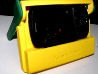
Support for Smartphone by Isarts3d
... keep the headset in a mobile base which is at the bottom of the holder.
moreover, it also serves to store the actual smartphone.
thingiverse
free

Bomboniere by Isarts3d
...e introduction of this key hole because of the way it is flush with the internal divisions, the chocolates hamper this operation.
thingiverse
free

Object holder with clock by Isarts3d
...e same color of the filament.
text translated by google translate from portuguese to english.
contact by email isarts3d@gmail.com
thingiverse
free

Abajour flower style by Isarts3d
...ated by google translator. so few words can get out of context.
any questions or problems, contact me by email isarts3d@gmail.com
thingiverse
free
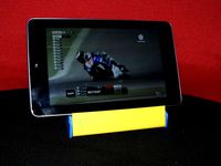
Universal Mobile Stand for Tablet by Isarts3d
...re the headset in a practical way.
for those who want to contact me, i leave my email is available, which is isarts3d@gmail.com
thingiverse
free

Center table classic style by Isarts3d
...would be expensive to produce all marble.
i made several renderings, experiencing different types of marbles. enjoy the pictures.
thingiverse
free

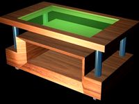
PROTOTYPE OF COLONIAL STYLE CENTER TABLE by Isarts3d
...pipes to support the lid.
for the installation of two ports, it is necessary to use hinges and clasps, which may be of metal.
thingiverse
free

Support for tablet in the car by Isarts3d
...t remove the top bracket and place the tablet. then fits the top of the bracket and has urged the tablet, with a frame around it.
thingiverse
free

SUPPORT FOR KNIFE by Isarts3d
...tten in portuguese, and automatically translated by google translator. for that reason they, may leave some words out of context)
thingiverse
free
PROTOTYPE OF A MINIATURE WOOD CENTER TABLE C / NICHE COVER AND GLASS by Isarts3d
...els).
i made several renderings, trying different settings and color wooden soundboard, whose images are available to be seen.
Conceptual
3ddd
free
conceptual furniture
...conceptual furniture
3ddd
сайт;
turbosquid
$10

Conceptual Robot
...d
royalty free 3d model conceptual robot for download as max on turbosquid: 3d models for games, architecture, videos. (1262561)
turbosquid
$15
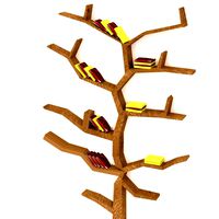
Conceptual Trees
...e 3d model conceptual trees for download as obj, fbx, and 3dm on turbosquid: 3d models for games, architecture, videos. (1440904)
turbosquid
$14

Conceptual Bed
... available on turbo squid, the world's leading provider of digital 3d models for visualization, films, television, and games.
turbosquid
$1
Conceptual gun 7
... available on turbo squid, the world's leading provider of digital 3d models for visualization, films, television, and games.
turbosquid
$1
Conceptual gun 6
... available on turbo squid, the world's leading provider of digital 3d models for visualization, films, television, and games.
turbosquid
$1

Conceptual gun 5
... available on turbo squid, the world's leading provider of digital 3d models for visualization, films, television, and games.
turbosquid
$1
Conceptual gun 4
... available on turbo squid, the world's leading provider of digital 3d models for visualization, films, television, and games.
turbosquid
$1

Conceptual gun 3
... available on turbo squid, the world's leading provider of digital 3d models for visualization, films, television, and games.
turbosquid
$1
Conceptual gun 2
... available on turbo squid, the world's leading provider of digital 3d models for visualization, films, television, and games.
Sustainable
turbosquid
$199

Sustainability Home
... available on turbo squid, the world's leading provider of digital 3d models for visualization, films, television, and games.
turbosquid
$10

Sustainable Speaker by People People
...odel sustainable speaker by people people for download as max on turbosquid: 3d models for games, architecture, videos. (1142184)
3d_export
$10

Skyscraper of the future on self-sustainment
...ar panels on the roof and at the same time collects rainwater, filters and supplies all residents of the house through pipe lines
3ddd
$1

Mid-Century Modern Viola Coffee Table
...modern viola coffee table ø20 x 18,75 cm certified sustainable bamboo,...
3ddd
$1
Neighbourhood Chair Pearl ByALEX
...design challenge for alex swain was to find a sustainable alternative to traditional hardwood. he discovered bamboo - as...
3ddd
free

Chair rig acacia adjustable barstool
...acacia adjustable barstool raising the bar. handcrafted round of sustainable acacia wood twists up/down three-and-a-quarter inches to park at...
3d_ocean
$9

Corques Sofa
...sofa uses cork as a basic shell material. this sustainable cork comes from production leftovers in portuguese bottle cork...
3d_export
$20

skovby set 26-table 63-chair
...effort and professional pride he created a foundation for sustainable and functional furniture design, which his son villy rasmussen...
3ddd
$1

Drommen bed
...drommen king bed designed by jannis ellenberger frame: solid sustainable acacia wood headboard: upholstered in ivory poly/linen with foam...
3ddd
free

M-Aduio Keystation 61es
...йка)
в архиве max2011 и max2014
polys: 88 022
ps. если вы купите эту модель 235 раз, я смогу купить ее себе настоящую :d :d :d
Self
3ddd
$1
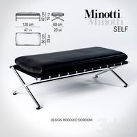
Self
... банкетка
каталог minotti 2010модель selfдизайнер rodolfo dordoniш\д\в 60\120\42
3ddd
$1
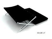
Minotti Self
...minotti self
3ddd
minotti
банкетка minotti self
3ddd
$1
Minotti Self
...minotti self
3ddd
minotti , self
текстуры и материалы прилагаются.
3ddd
$1
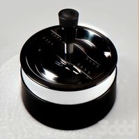
Self cleaning ashtrays
...self cleaning ashtrays
3ddd
пепельница
self cleaning ashtrays
turbosquid
$15
Book self
...
royalty free 3d model book self for download as max and fbx on turbosquid: 3d models for games, architecture, videos. (1502520)
3d_export
free
self-tapping screw
...self-tapping screw
3dexport
self-tapping screw 55 мм
turbosquid
$12

Book Self
...lty free 3d model book self for download as max, obj, and fbx on turbosquid: 3d models for games, architecture, videos. (1473695)
turbosquid
$4
Self with Desk
...d model self with desk for download as 3ds, max, obj, and fbx on turbosquid: 3d models for games, architecture, videos. (1511139)
turbosquid
$2

Book Self
...ree 3d model book self for download as max, fbx, 3ds, and obj on turbosquid: 3d models for games, architecture, videos. (1544366)
turbosquid
$2

Book self
...ree 3d model book self for download as 3ds, max, fbx, and dwg on turbosquid: 3d models for games, architecture, videos. (1300384)
Building
archibase_planet
free
Building
...building high-rise building office building construction
building n050115 - 3d model (*.gsm+*.3ds) for exterior 3d visualization.
3d_export
$5
building
...building
3dexport
clasic building
3ddd
$1
building
...building
3ddd
здание
building
archibase_planet
free
Building
...lanet
building office office building construction
building n090914 - 3d model (*.gsm+*.3ds+*.max) for exterior 3d visualization.
archibase_planet
free
Building
...net
building tower construction high-rise building
building n100214 - 3d model (*.gsm+*.3ds+*.max) for exterior 3d visualization.
3d_export
free
Building
...building
3dexport
low poly building;
3d_export
free
Building
...building
3dexport
low poly building;
3d_export
free
Building
...building
3dexport
low poly building;
3d_export
free
Building
...building
3dexport
low poly building;
3d_export
free
Building
...building
3dexport
low poly building;
Design
3ddd
$1
LINE DESIGN (Doors Design)
...line design (doors design)
3ddd
дверь
modern doors design - line design concept
3ddd
$1
VER DESIGN
...ver design
3ddd
ver design
кресло ver design
3ddd
$1
VER DESIGN
...ver design
3ddd
ver design
диван ver design
3ddd
$1
Bagno design
...bagno design
3ddd
bagno design , унитаз
санитария bagno design
3ddd
free
VER DESIGN
...ver design
3ddd
ver design , стеллаж
полка ver design
3ddd
$1
VER DESIGN
...ver design , лежак , шезлонг
шезлонг ver design
3d_export
free
designer
..., trees and much more. the model has 3 types of parts: - 4 cells - 6 cells - 8 cells the *.max file contains 5 colored materials.
3d_export
$19
level design
...level design
3dexport
you can use this design (level design) in your own game.
3d_export
$7
Crusher design
...crusher design
3dexport
crusher design
3d_export
$4
interior design
...interior design
3dexport
interior design