Thingiverse
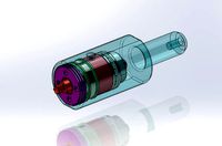
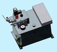
Compact housing for PID controller and Solid State Relay by glassy
by Thingiverse
Last crawled date: 3 years ago
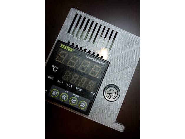
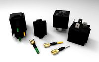
Wanted a compact SESTOS D1S-VR-220 PID controller and Ink Bird SR-25 DA Solid State Relay Module enclosure, with a switch, fusebox and possibility to monitor SSR On-light.
So here it is.
https://youtu.be/IEsE7TQns0Mhttps://youtu.be/RfjG2W9W8D4
Fuse holder dimensions are: body_length 35mm; front_diameter 14,9mm; front length 5,7mm; thread diameter 12,40mm.
-Switch dimensions are: 11mm / 30mm.
-Also used four M3x6 countersunk screws for fixing back to front. They screw int directly into the plastic (no need for nuts);
one M3x6 countersunk screw and one M3 nut for tightening the PID controller in place (from the side);
-one M3x10 countersunk screw and one M3 nut for tightening the SSR inside the housing.
The following order of assembly worked for me:
attach all the wires to SSR (use thin ones for control clamps)
move the SSR in (see that SSR LED is right below its opening on top) and secure it with the screw and nut (tighten the screw through the hole on the top)
solder wire to the side contact of the fuse housing and install the fuse from the front. Use
long tweezers to screw on the nut;
install the switch into the back part (might need a touch with a flat file to fit it in) depending on your print tolerance and pass in all the wires through the holes in the back part. The oval hole I used for the mains power, the round for the heater and the key-like hole for the thermo-pair (mine was already with contacts pressed on hence the shape of the hole to get in one contact after other);
put a nut from inside of the side wall and screw in the M3x6 screw slightly from outside so the nut just doesn't fall out. Press in the PID controller from the front (the front opening might need a touch with a flat file to fit it in);
solder the wire to the end contact of the fuse holder.
connect wires to the PID controller and the solder the other ends to the switch.
Place the back part into the front part and secure it with remaining four M3x6 screws.
If you found my design useful or inspiring and would like to buy me a cup of espresso you are welcome to tip me:
https://www.paypal.com/cgi-bin/webscr?cmd=_s-xclick&hosted_button_id=U25V96GZNVL3N&source=url
Thank you!
Similar models
thingiverse
free

PID Controller Case by AndrewOlvera
... through hole to secure.
wire
countersunk screws 4-40 or m3
screws for heat sink
screws for feet
optional feet or print from file
thingiverse
free

PID control box by bbo
... power cord plugin in the back.
print the two parts separately to minimize delamination.
filament extruder temperature controller
thingiverse
free

DIN rail mount SSR 25 DA by mottamx
... for a 6x6mm nut to fit (slide in). align the hole with a wire or a small screwdriver tip (with the ssr), then insert the screws.
thingiverse
free

PID Control Housing - 3D Touch BFB by valentFx
... housing for pid controller, ssr, switch, fuse, powerinput. i used this to temperature control the print bed for a bfb 3d touch.
thingiverse
free

PID Control Box - Kiln/Foundry
...double sided tape on the overlapping surfaces to fix the heat sink to the control box.
be careful playing with mains electricity!
thingiverse
free

PID Box by night--wolf
...nt , and wires in the back.
may have to adjust holes alittle bit with a drill,
and file the square hole for the pid controller.
thingiverse
free

Screw power switch for combat robots by JEQuad
...a soldering iron 16-20 awg silicon wire so something similar depending your use steps: file one side of the...
grabcad
free

SSR-40 DA
...ssr-40 da
grabcad
this is a solid state relay that controls 24-380vac with pid
thingiverse
free

sous vide box by jwtje
...sh surface. i always make holes oversized because holes will always come out smaller than drawn. so the holes are 3,5mm diameter.
thingiverse
free

My PowerSwitch by Wipo
...2 mm higher) but all in all i just mounted it like this and it seems to fit well. one needs to drill two holes in the side panel.
Glassy
3d_ocean
$2

Glassy Ashtrays
...glassy ashtrays
3docean
ashtray bar cigarettes glas glassy smoking
three glassy ashtrays (clear, brown, black)
3d_ocean
$15

Glassy chairs
...ul furniture glassy house modern set stool
this are glassy bar chairs in the composition of 5 colours. colours are easy to edit:)
turbosquid
free

Glassy Mosque
...ee 3d model glassy mosque for download as blend, dae, and obj on turbosquid: 3d models for games, architecture, videos. (1712996)
turbosquid
$1

Glassy flowers
... available on turbo squid, the world's leading provider of digital 3d models for visualization, films, television, and games.
3d_export
$6

Glassy lamp 3D Model
...glassy lamp 3d model
3dexport
lamp glass steel bulb gray modern classic
glassy lamp 3d model sams 94124 3dexport
3d_ocean
$1

Set of 22 Glassy Arrows
... stubby, tapered – there’s loads to choose from: check out the preview images. shader. they are ready to render in 3ds max. al...
3d_ocean
$9

10 Glassy Materials for Cinema 4D R12
...d r12
3docean
• 10 c4d glass materials with different colors • opens with cinema 4d r12 • render setup included in the .c4d file
3d_export
$15

Table 3D Model
...table 3d model 3dexport table design interior good glassy furniture table 3d model vn 60029...
3d_export
$6

Woody Door 3D Model
...door 3d model 3dexport msaatchi woody door interior simple glassy vray wood material woody door 3d model msaatchi 4380...
3d_export
$12

Lift 3D Model
...height skyscraper transparent lift move up down saving time glassy elevator lift 3d model dmitry87 38144...
Pid
3ddd
$1

Водные горки: Compact Slide, Aquatube, Multislide, Freefall, Kamikaze
...-http://ru.polin.com.tr/lecatalogue/productdetail.aspx?pid=363 multi slide -http://www.polin.com.tr/lecatalogue/productdetail.aspx?pid=24 aquatube - http://ru.polin.com.tr/lecatalogue/productdetail.aspx?pid=367#!prettyphoto compact slide -http://ru.polin.com.tr/lecatalogue/productdetail.aspx?pid369 ...
3ddd
free

Circa lighting, люстра, бра
...designer thomas o'brien item # chd1495 | designer e.f. chapmanhttp://www.circalighting.com/details.aspx?pid1889 http://www.circalighting.com/details.aspx?pid=572 ...
3ddd
$1

Hinkley Lighting
...hinkley lighting 3ddd hinkley lighting http://www.hinkleylighting.com/products/product-detail.aspx?pid2644 ...
3ddd
$1

Jessica Mcclintock Collection
...jessica mcclintock collection 3ddd комод , jessica mcclintock http://www.americandrew.com/productpage.cfm?pid9365 ...
3ddd
$1

Circa lighting item CHC1112
...circa lighting item chc1112 3ddd circa light http://www.circalighting.com/details.aspx?pid339 ...
3ddd
free

SICILIA
...sicilia 3ddd sicilia , ванна , угловая http://www.victoryspa.net/produkt.php?lg=10&pid=19 ...
3ddd
$1

Councill LOGAN SIDEBOARD
...councill logan sideboard 3ddd сouncill , комод http://www.councill.com/product.asp?pid5046&cid;=108 ...
3ddd
$1

Водные горки: Tsunami, Space Hole, Space Boat.
...на продукцию: tsunami -http://ru.polin.com.tr/lecatalogue/productdetail.aspx?pid=336 space hole -http://ru.polin.com.tr/lecatalogue/productdetail.aspx?pid=335 space boat -http://ru.polin.com.tr/lecatalogue/productdetail.aspx?pid334 ...
3ddd
$1

Ozcan SENFONI
...ozcan senfoni 3ddd ozcan потолочный светильник фабрики ozcanhttp://www.ozcanaydinlatma.com.tr/senfoni.aspx?pageid=151&pid=1541 ...
3ddd
$1

EFLM CH7004 Slipper Chair
...eflm ch7004 slipper chair 3ddd eflm http://www.ef-lm.com/product_detail.aspx?pid13146&lo;=16 ...
Relay
turbosquid
$50
Relay Spaceship
... model relay spaceship for download as skp, 3ds, dae, and obj on turbosquid: 3d models for games, architecture, videos. (1655800)
3ddd
$1
Scavolini / Grand Relais
...scavolini / grand relais
3ddd
scavolini
scavolini модель grand relais дизайн gianni pareschi
3ddd
$1
Сантехника Globo Relais
... унитаз , зеркало
сантехника globo relais
умывальник,зеркало,унитаз.
3d_export
$8
relay automatic assembly line
...relay automatic assembly line
3dexport
relay automatic assembly line
3ddd
free
Унитаз и биде Relais
... биде , унитаз
унитаз art.re001 bi и биде art.re009 bi
turbosquid
free

Relay 8 pin
... available on turbo squid, the world's leading provider of digital 3d models for visualization, films, television, and games.
cg_studio
$110
Power relay station3d model
...el
cgstudio
.3ds .fbx .max .obj - power relay station 3d model, royalty free license available, instant download after purchase.
3ddd
$1
Стол обеденный -Scavolini- Grand Relais
...s
3ddd
обеденный , scavolini
обеденный стол scavolini - grand relais, в трёх расцветках.
3d_export
$10
relay jd1912 12v 40a with connector
...lowing bodies: 1. relay jd1912 12v 40a - 1 piece; 2. connector housing - 1 piece; 3. terminal with a part of the wire - 4 pieces.
3ddd
free

Globo Relais furnitures
... , раковина
раковина с консолью st070.ne
зеркалоsp070.bi
стакан re0381x
мыльница re0391x
Compact
3d_export
$5

compact freezer
...compact freezer
3dexport
the compact freezer is product about refrigeration machine
3d_ocean
$8
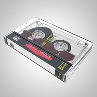
Compact Cassette
...
80s album analog audio cartridge cassette compact digital electronics lp mp3 music play record sound tape vinyl
compact cassette
design_connected
$20
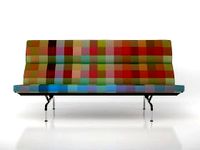
Eames Compact
...eames compact
designconnected
herman miller eames compact computer generated 3d model. designed by eames, charles.
3d_ocean
$2

Compact Disc
...compact disc
3docean
album audio cd compact disc dvd laser disc movie music
a cd
3d_export
$10

land compacter
...land compacter
3dexport
turbosquid
$1
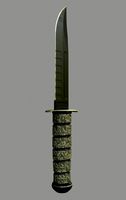
Compact knife
...quid
royalty free 3d model compact knife for download as obj on turbosquid: 3d models for games, architecture, videos. (1557900)
3d_export
$12
compact rotary broach
...compact rotary broach
3dexport
compact tool for drilling hexagonal holes in lathes!
turbosquid
free

Lada Compact
... 3d model lada compact for download as max, max, max, and fbx on turbosquid: 3d models for games, architecture, videos. (1623122)
turbosquid
$59

Compact Truck
... available on turbo squid, the world's leading provider of digital 3d models for visualization, films, television, and games.
turbosquid
$50
Compact kitchen
... available on turbo squid, the world's leading provider of digital 3d models for visualization, films, television, and games.
State
turbosquid
$9

Lyon States
...osquid
royalty free 3d model lyon states for download as stl on turbosquid: 3d models for games, architecture, videos. (1431758)
turbosquid
$5

Empire state
... free 3d model empire state for download as 3ds, obj, and c4d on turbosquid: 3d models for games, architecture, videos. (1310013)
turbosquid
$150

USA States
... available on turbo squid, the world's leading provider of digital 3d models for visualization, films, television, and games.
3d_export
$350

USA states 3D Model
...usa states 3d model
3dexport
usa states
usa states 3d model wickiupinfo 62636 3dexport
turbosquid
free

Empire State Building
...quid
free 3d model empire state building for download as c4d on turbosquid: 3d models for games, architecture, videos. (1509366)
turbosquid
$199

us state department
...royalty free 3d model us state department for download as c4d on turbosquid: 3d models for games, architecture, videos. (1658806)
turbosquid
$59

State House Building
...oyalty free 3d model state house building for download as max on turbosquid: 3d models for games, architecture, videos. (1248175)
turbosquid
$19

Colorado State Seal
...royalty free 3d model colorado state seal for download as max on turbosquid: 3d models for games, architecture, videos. (1291867)
turbosquid
$18

BISHKEK-STATE-CIRCUS
...oyalty free 3d model bishkek-state-circus for download as max on turbosquid: 3d models for games, architecture, videos. (1388670)
turbosquid
$1

State Park Trailhead
...oyalty free 3d model state park trailhead for download as fbx on turbosquid: 3d models for games, architecture, videos. (1648408)
Solid
turbosquid
$70

Solider
...er
turbosquid
royalty free 3d model solider for download as on turbosquid: 3d models for games, architecture, videos. (1232788)
3d_export
$6

newjoy - solid
...;br>shelf - solid sd-1400 - 120х30х74<br>table - solid sd-1401 - 123х65х89<br>bookcase - solid sd-1500 - 85х35х176
3d_ocean
$3

Vray Solid Glass
...vray solid glass
3docean
3dmax glass material solid glass vray
vray solid glass for 3dmax
turbosquid
$5

Toy Solider
...royalty free 3d model toy solider for download as png and stl on turbosquid: 3d models for games, architecture, videos. (1398359)
turbosquid
$1

Solid Table
...y free 3d model solid table for download as max, obj, and fbx on turbosquid: 3d models for games, architecture, videos. (1418669)
3d_export
$8

solid wood chair
...solid wood chair
3dexport
solid wood chair. have texture
turbosquid
$20

Solid Snake
... available on turbo squid, the world's leading provider of digital 3d models for visualization, films, television, and games.
turbosquid
$15

Chair solid
... available on turbo squid, the world's leading provider of digital 3d models for visualization, films, television, and games.
turbosquid
$11

archimedean solids
... available on turbo squid, the world's leading provider of digital 3d models for visualization, films, television, and games.
turbosquid
$5

Bed Solid
... available on turbo squid, the world's leading provider of digital 3d models for visualization, films, television, and games.
Controller
3d_ocean
$4
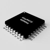
Controller TQFP32
...qfp32
3docean
chip controller cpu electronic gpu mcu micro controller silicon smd tqfp wafer
a micro controller in tqfp32 package
3d_ocean
$4
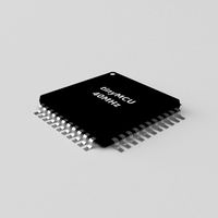
Controller TQFP44
...44
3docean
chip controller cpu electronic gpu mcu micro controller package smd tqfp tqfp44
a micro controller in a tqfp44 package
3d_export
$15
control unit
...control unit
3dexport
control unit
3ddd
$1
Yacht control
...yacht control
3ddd
yacht control
3d_export
$5
controle pgdm
...controle pgdm
3dexport
carcaca controle pgdm
turbosquid
free
controler
... available on turbo squid, the world's leading provider of digital 3d models for visualization, films, television, and games.
3ddd
$1
Control
...
http://www.schmitz-leuchten.de/html-ru/einzelleuchten-lampentyp-details.php?lamptype_no=700&group;=917&id;=731
3d_ocean
$4
Controller TQFP100
...100
3docean
chip computer cpu electronic gpu mcu micro controller pin platine silicon wafer
a micro controller in tqfp100 package
3d_ocean
$4
Controller TQFP64
...qfp64
3docean
chip computer cpu gpu mcu micro controller package silicon tqfp tqfp64 wafer
a micro controller in a tqfp64 package
3d_ocean
$7

Remote controller
... control switcher tv remote
remote controller for tv, sound systems etc easy to edit textures photo real rendered with mental ray
Housing
archibase_planet
free
House
...t
house residential house private house wooden house
house wooden n290815 - 3d model (*.gsm+*.3ds) for exterior 3d visualization.
archibase_planet
free
House
...use residential house private house wooden house
house wood stone n140815 - 3d model (*.gsm+*.3ds) for exterior 3d visualization.
archibase_planet
free

House
...ibase planet
house residential house building private house
house n050615 - 3d model (*.gsm+*.3ds) for exterior 3d visualization.
archibase_planet
free

House
...ibase planet
house residential house building private house
house n030615 - 3d model (*.gsm+*.3ds) for exterior 3d visualization.
archibase_planet
free
House
...ibase planet
house residential house building private house
house n230715 - 3d model (*.gsm+*.3ds) for exterior 3d visualization.
archibase_planet
free

House
...ibase planet
house residential house building private house
house n240615 - 3d model (*.gsm+*.3ds) for exterior 3d visualization.
archibase_planet
free

House
...ibase planet
house residential house building private house
house n290815 - 3d model (*.gsm+*.3ds) for exterior 3d visualization.
archibase_planet
free

House
...ibase planet
house residential house building private house
house n110915 - 3d model (*.gsm+*.3ds) for exterior 3d visualization.
archibase_planet
free
House
...ibase planet
house residential house building private house
house n120915 - 3d model (*.gsm+*.3ds) for exterior 3d visualization.
archibase_planet
free
House
...ibase planet
house residential house building private house
house n210915 - 3d model (*.gsm+*.3ds) for exterior 3d visualization.