Thingiverse
CobbleBot Horizontal X Axis Mod V3 by CthulhuLabs
by Thingiverse
Last crawled date: 3 years ago
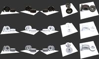
This is version 3 of my CobbleBot X Axis mod. Don't bother looking for verison 2, I did not post it. This has completely removed the issue of X backlash for me and I can now properly print with my printer.
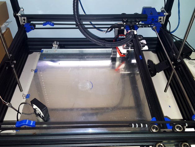
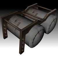
This mod basically attaches a drive shaft to the X stepper motor that then drives two belt pulleys. One at the top of the X plane and one at the bottom. This keeps each end of the Y axis moving as one. The stepper is mounted outside the frame of the gantry and the drive shaft runs just underneath the gantry. The coupler for the drive shaft is inside the stepper mount. There is a slot in the stepper mount for turning the set screws on the coupler.
In addition to the printed parts you are going to need four 625 radial bearings, two idler pulleys, a 5mm drive shaft, two 5mm pulleys, and a 5mm to 5mm coupler. Here are the ones I used:
Bearing - http://openbuildspartstore.com/ball-bearing-625-2rs-5x16x5/
Idler - http://openbuildspartstore.com/smooth-idler-pulley-wheel-kit/
Pulley - http://www.amazon.com/gp/product/B00THZJNTI?psc=1&redirect=true&ref_=oh_aui_detailpage_o01_s00
Coupler - http://www.amazon.com/EnPoint-Flexible-Aluminum-Coupling-Backlash/dp/B016F2E92G/ref=sr_1_7?s=industrial&ie=UTF8&qid=1447884138&sr=1-7&keywords=enpoint+5mm+coupler
The drive shaft is a 5mm drill rod that I got from McMaster Carr, but their website doesnt allow me to directly link to it. It is literally 5mm which the hole in the bearings are actually a little smaller than 5mm. To compensate for this I had to put the drill rod into a drill and use sand paper to take off a few thousandths to get the bearings over the drive shaft.
You will also need screws and t nuts to mount everything to the vslot rails.
As always I have included the google sketchup files so people can easily make changes.
EDIT: Added some additional pictures of the motor mount. You can see the slot on the top for accessing the set screws for the coupler.
Update 2016-01-18:
Modified the X-Axis-Idler-Mount so it can get closer to the rails
Modified the X-Axis-Drive-Shaft-Mount so it can get closer to the rails.
Modified the X-Axis-Drive-Shaft-Mount to strengthen the area around the bearings.
Update: 2016-02-04:
Created a new X-Axis-Drive-Shaft-Mount that is very different than my other design. This design can be printed without supports and with the bearing holder laying flat. The print quality is much better with it. You should print four of this one, two of which you should invert so the bearing mount is on the other side. This allows you to spread the bearings out evenly along the drive shaft rather than just at the ends.
Update: 2016-04-08:
Change the X-Axis-Idler-Mount so that the tension is adjustable and prints without supports. Requires 2 35mm M3 bolts and 2 M3 nuts to hold the two halves together. For the Idler adjustments you need 2 15mm M5 bolts and 2 M5 nuts plus a 30mm length of 5mm diameter rod.
Update: 2017-09-20:
Redesigned the X-Axis-Drive-Shaft-Mount mount yet again. This time in Fusion360. The part is stronger and has two attachment points instead of one. It can still be printed without supports. I recommend at least 50% infill for strength. You will need 2x M4 nuts and appropriate t-slot bolts for mounting. I added a chamfer to make pressing the bearing in easier. I recommend a C clamp for that.
Similar models
thingiverse
free

CobbleBot Horizontal X Axis Mod V3 for moving bed by tomtom2770
...ts and m3 screws. to hold the belt in place you can close the gap with another m3 screw.
designed by tim ogermann and tom cinbis
thingiverse
free

CobbleBot Horizontal X Axis Mod by CthulhuLabs
...s i am having issues meeting tolerances on the x. i am including the sketchup files so you can make any adjustments you may need.
thingiverse
free

Ender 5 Y-axis Single Shaft Mod by eggzzzzzzzzz
...extrusion.
you need a different stepper bracket, two 608 bearings, an 8mm shaft, plus pulleys for the motor shaft and 8mm shaft.
thingiverse
free

5mm-8mm Coupler Mod-XC51100 bearing by Kannonballer
... prolong the life of your stepper motor, eliminate any drag that can happen when the coupler works its way down during operation.
thingiverse
free

Ender 5 Y-Axis Drive Support Bracket
...-nuts each. uses the same f688 bearing as the oem brackets. tight fit if your printer is tuned. i printed .2mm layer, 50% infill.
thingiverse
free

Shaft Coupler for stepper motor 8mm x 5mm and 8mm x 6.35mm
.... one is 8mm to 5mm and the other one is 8mm to 6.35mm shaft diameters.use 2 x m3 capscrew and nut for each to clamp it to shafts
thingiverse
free

Claw coupler by mrmimo
...lts.
i attach two hubs - one for 5mm and one for 8mm shaft. i also add a generic hub with no hole at all so you can customize it.
thingiverse
free
5mm to 8mm Z axis shaft coupler by mrice
...ible shaft couplers on z axis rods, for 5mm motor shafts and 8mm threaded rods. use two m3x10mm screws and nuts to tighten down.
grabcad
free

shaft coupler
...shaft coupler
grabcad
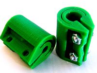
on my stepper axis i have made this shaft coupler with 5mm hole and 2 locker.
thingiverse
free

28BYJ-48 Stepper Shaft - z-axis Coupler by Solarmax
...herry-60-3d-printer/ by vulcaman. however, they could be used for other printers using the 28byj-48 stepper and 5mm threaded rod.
Cthulhulabs
thingiverse
free

Retraction Test by CthulhuLabs
...over filled. seemed to be retraction related. am currently using this piece to dial in the retraction and deal with other issues.
thingiverse
free

Adjustable Belt Tensioner by CthulhuLabs
...i recommend using nylon bolts for the adjustment screws so you can cut off the excess when you are done tightening the tensioner.
thingiverse
free

Screw Terminal Block by CthulhuLabs
...lacing this directly on plastic you don't really need plate 1. its mainly there as an electrical insulator on metal surfaces.
thingiverse
free

Mounting Plate for dc42's IR Probe For Coreception (Elf) 3D Printer by CthulhuLabs
...reception (elf) 3d printer by cthulhulabs
thingiverse
mount for dc42's ir probe on the sainsmart coreception 300 3d printer.
thingiverse
free

2020 V Slot Mount Base by CthulhuLabs
...ures two 5m mount holes as well as notches to help align 15mm long tnuts with those holes. figured it would be useful for others.
thingiverse
free

SnapMaker Dremel Flex Shaft Mount by CthulhuLabs
...dremel flex shaft
please note that i have not tested this at all. i am not sure i have it even in the correct place on the mount.
thingiverse
free

CobbleBot X axis belt block by CthulhuLabs
...hers to get the height adjusted properly.
update:
check out this remix: http://www.thingiverse.com/thing:1072943 its much better.
thingiverse
free

SnapMaker Z Spacer Block by CthulhuLabs
...the build volume i made this spacer that will go at the bottom.
requires 4x 60mm m4 bolts to attach the z axis to the base plate.
thingiverse
free

Screw Together Belt Tensioner by CthulhuLabs
...ls thicker than the ones i was finding on here. the screw holes are places so that they do not get in the way of the belt travel.
thingiverse
free

SnapMaker Part Cooler by CthulhuLabs
...osition or you will hit it when homing the z axis. i did not realize this when i designed this as i had already moved the screen.
Cobblebot
thingiverse
free

Cobblebot rises by NucleoBLAST
...cobblebot rises by nucleoblast
thingiverse
the pieces of the new cobblebot revolution.
thingiverse
free

Cobblebot LCD Box by Linax
... i got from cobblebot didnt fit the lcd so i designed a box for it.
can be monted on the bottom 60mm or on any of the 20mm rails.
thingiverse
free

Cobblebot X-Axis by t3pnarcosis
...ted a smaller version of the cobblebot x block. still has a strong design at about half the size, no need to use shims or spacer.
thingiverse
free

COBBLEBOT Z MOUNT by Andreascha78
...h on z axis on the cobblebot, and relocates the lead screw bushing closer to the frame.
results may vary according to your setup.
thingiverse
free

Cobblebot Roller Bearing Shims or Washers by Mapembert
...d on assembly here:http://suburbnerd.blogspot.com/2015/11/cobblebot-roller-bearing-fix-with-3-d.html
https://youtu.be/_95jtjwnvda
thingiverse
free

cobblebot cable mangement m5 by cyde
... basic, but can be used anywhere a m5 bolt can be used.
scad files provided so people can tinker.
can be printed with no support.
thingiverse
free

Cobblebot Indicator holder by t3pnarcosis
...cobblebot indicator holder by t3pnarcosis
thingiverse
i used this with a harbor freight indicator to help level out my bed.
thingiverse
free

Cobblebot Proximity Sensor Mount by mbarry8859
...mple to mount my blue tip prox sensor to my cobblebot v2. there are others out there, but i wanted one that fit a little better.
thingiverse
free

Cobblebot Endstop by cyde
...bolt needed to the 20x20 frame
and 2 m3 bolt/nuts to attach the endstop board.
its quick and dirty but works (mounted both ways).
thingiverse
free

Arduino Holder for CobbleBot Vanguard by ThorMJ
...posts that go through the arduino are tapered; if you slice at 0.2 or 0.3, the arduino will lock in place when you press it down.
V3
3d_export
$5

Poison-v3
...poison-v3
3dexport
poison-v3
3ddd
$1

Curtain v3
...curtain v3
3ddd
полупрозрачная штора v3
turbosquid
free

v3
... available on turbo squid, the world's leading provider of digital 3d models for visualization, films, television, and games.
3d_export
$5

potato v3
...potato v3
3dexport
turbosquid
$69

Skeletor v3
...royalty free 3d model skeletor v3 for download as ztl and obj on turbosquid: 3d models for games, architecture, videos. (1712713)
turbosquid
$49

Zombie v3
...
royalty free 3d model zombie v3 for download as obj and ztl on turbosquid: 3d models for games, architecture, videos. (1342458)
turbosquid
$2

Bitcoin v3
...
royalty free 3d model bitcoin v3 for download as c4d and prj on turbosquid: 3d models for games, architecture, videos. (1182845)
turbosquid
$29
Turret V3
...alty free 3d model turret v3 for download as ma, obj, and fbx on turbosquid: 3d models for games, architecture, videos. (1217498)
turbosquid
$20
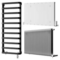
Radiators v3
... free 3d model radiators v3 for download as max, max, and obj on turbosquid: 3d models for games, architecture, videos. (1607437)
turbosquid
$10
Wheel V3S
...e 3d model wheel v3s for download as 3ds, obj, fbx, and blend on turbosquid: 3d models for games, architecture, videos. (1344250)
Horizontal
3ddd
$1

Zephyr Horizont
...zephyr horizont
3ddd
вытяжка , zephyr
вытяжка zephyr horizont
design_connected
$13

Mr.Tubes Horizontal
...mr.tubes horizontal
designconnected
tonone mr.tubes horizontal computer generated 3d model.
3d_export
$5

Horizontal bars
...orizontal bars
3dexport
this is a large horizontal bar for rhythmic gymnastics, as well as for pull-ups and many other exercises
3d_export
$5
Horizontal circular saw
...horizontal circular saw
3dexport
horizontal circular saw
turbosquid
$13

Horizontal tank
...id
royalty free 3d model horizontal tank for download as fbx on turbosquid: 3d models for games, architecture, videos. (1709417)
turbosquid
$1

Decor horizontal
...
royalty free 3d model decor horizontal for download as sldpr on turbosquid: 3d models for games, architecture, videos. (1256236)
3ddd
free
tiling horizontal decoratives
...tiling horizontal decoratives
3ddd
штукатурка
tiling horizontal decorative texture
turbosquid
$19

The horizontal bar
... model the horizontal bar for download as , fbx, stl, and obj on turbosquid: 3d models for games, architecture, videos. (1684719)
turbosquid
$10

Horizontal Bar
...ree 3d model horizontal bar for download as max, obj, and fbx on turbosquid: 3d models for games, architecture, videos. (1435728)
turbosquid
$15
Horizontal Bar
...d model horizontal bar for download as 3ds, max, obj, and fbx on turbosquid: 3d models for games, architecture, videos. (1317823)
Mod
design_connected
$13

MOD. 4233 - MOD. 4234 Table Lamp
...mod. 4233 - mod. 4234 table lamp
designconnected
arcahorn mod. 4233 - mod. 4234 table lamp computer generated 3d model.
design_connected
$11

MOD.1095
...mod.1095
designconnected
mod.1095 computer generated 3d model. designed by sarfatti, gino.
3ddd
$1

fireplaces mod Spec
...fireplaces mod spec
3ddd
камин
fireplaces mod spec 180x90x125h
3ddd
free

Flos Mod. 2129
... mod
фабрика: flos
модель: mod. 2129
описание: подвесной светильник, металл, белый, черный.
сайт: www.flos.com
turbosquid
$34

Mod Lamp.c4d
... available on turbo squid, the world's leading provider of digital 3d models for visualization, films, television, and games.
turbosquid
$32
MOD A 001
... available on turbo squid, the world's leading provider of digital 3d models for visualization, films, television, and games.
turbosquid
$29
Maars Mod
... available on turbo squid, the world's leading provider of digital 3d models for visualization, films, television, and games.
turbosquid
$15

Mod 70..
... available on turbo squid, the world's leading provider of digital 3d models for visualization, films, television, and games.
turbosquid
$10

MOD Sofa
... available on turbo squid, the world's leading provider of digital 3d models for visualization, films, television, and games.
turbosquid
$1

Mod-Lite
... available on turbo squid, the world's leading provider of digital 3d models for visualization, films, television, and games.
Axis
3ddd
$1

Мария Axis
...
3ddd
кухня , классическая , axis
модель кухни.
3d_export
$22
Axis robot 6-axis robotic arm
...ing parts drawings, standard parts purchased parts list, can be produced directly according to the drawings, welcome to download!
3ddd
free

Versatile Axis
...ddd
nexus , плитка
http://bvtileandstone.com/ceramic-porcelain/versatile-axis/
3d_export
$19
robot 2 axis
...robot 2 axis
3dexport
robot 2 axis
turbosquid
$40

Axis R5F
... available on turbo squid, the world's leading provider of digital 3d models for visualization, films, television, and games.
turbosquid
$40

Axis S5F
... available on turbo squid, the world's leading provider of digital 3d models for visualization, films, television, and games.
turbosquid
$30

Axis Athlon
... available on turbo squid, the world's leading provider of digital 3d models for visualization, films, television, and games.
turbosquid
$10

Linear Axis
... available on turbo squid, the world's leading provider of digital 3d models for visualization, films, television, and games.
3d_export
$15

drawing axis
...drawing axis
3dexport
simple rendering of the scene file
3ddd
$1

versatile axis ARC
...versatile axis arc
3ddd
versatile , плитка
versatile axis arc red dot design award