GrabCAD
Classic Escapement - Graham (Modified)
by GrabCAD
Last crawled date: 1 year, 11 months ago
This is the continuation of my former project Classic Escapement - Graham (Ideal).
Based on the book CLOCK AND WATCH ESCAPEMENT MECHANICS by Mark V. Headrick (Copyright 1997) as a fine source, I try to present rigorously the essence of escapement design. The book is public and you can find it here: http://www.nawcc-index.net/Articles/Headrick-EscMechanics.pdf, so you can read and compare (with the book) everything I present here. I recommend you to download the book in order to use it when your computer is offline.
All parts, assemblies and simulation/animation are made with Inventor 2014, so some specific references are bonded to this software.
This is the presentation of the Modified Graham escapement explained in the book between page 11 („5: The Importance of the Simulation”) and page 15.
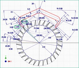
Firstly you have to look to the picture showing the Inventor sketch „Wheel - Palette modified.jpg”. The difference from the Ideal escapement (see https://grabcad.com/library/classic-escapement-graham-ideal-1) is that the left and right ends of the palette are thinned, so they are now able to enter between the teeth of the wheel. You notice the angle of 2° on each side of the palette, accordingly with the explanations in the book at the page 11.
Watching the Video you see immediately the movement of the palette, due to the pendulum which is jointly to it. Now the rotation of the wheel is permanent, step by step. Why? Because of the imposed motion, this is why. Again, when the mechanism is presented from the back you understand that a thread and a weight must be spooled on the reel to produce the motion. They are not present because threads/ropes are not allowed in Dynamic Simulation in Inventor. Instead, a torque (of only 6 N·mm) is applied to the reel.
The wheel feeds the movement of the pendulum so the pendulum is permanently maintained swinging. This is made because of the perpendicular placement of the red faces of the palette shown in the picture „Contact and impulse faces.jpg”. This is really important, and the book emphasis the aspect. A small part of the wheel energy is transferred to the pendulum each time the palette sweep the teeth with these faces. You understand that the potential energy of the virtual weight which hangs on the reel is consumed on this way almost strictly to feed the pendulum movement. Longer the contact face - greater useful energy is transferred from the wheel. This is why we carefully thin the arms of the palette, and that two degrees are awarded sparingly.
Included are the files „Output Grapher (10s).jpg” and „Output Grapher (60s).jpg” where you can see the graphs of movement of the wheel and the palette. The points considered are the same A and B as in the previous project (Ideal). When the time is longer (60s) you can see an increase of the amplitude of palette oscillation. This can be adjusted by changing the length of the pendulum rod.
Enjoy!
Based on the book CLOCK AND WATCH ESCAPEMENT MECHANICS by Mark V. Headrick (Copyright 1997) as a fine source, I try to present rigorously the essence of escapement design. The book is public and you can find it here: http://www.nawcc-index.net/Articles/Headrick-EscMechanics.pdf, so you can read and compare (with the book) everything I present here. I recommend you to download the book in order to use it when your computer is offline.
All parts, assemblies and simulation/animation are made with Inventor 2014, so some specific references are bonded to this software.
This is the presentation of the Modified Graham escapement explained in the book between page 11 („5: The Importance of the Simulation”) and page 15.
Firstly you have to look to the picture showing the Inventor sketch „Wheel - Palette modified.jpg”. The difference from the Ideal escapement (see https://grabcad.com/library/classic-escapement-graham-ideal-1) is that the left and right ends of the palette are thinned, so they are now able to enter between the teeth of the wheel. You notice the angle of 2° on each side of the palette, accordingly with the explanations in the book at the page 11.
Watching the Video you see immediately the movement of the palette, due to the pendulum which is jointly to it. Now the rotation of the wheel is permanent, step by step. Why? Because of the imposed motion, this is why. Again, when the mechanism is presented from the back you understand that a thread and a weight must be spooled on the reel to produce the motion. They are not present because threads/ropes are not allowed in Dynamic Simulation in Inventor. Instead, a torque (of only 6 N·mm) is applied to the reel.
The wheel feeds the movement of the pendulum so the pendulum is permanently maintained swinging. This is made because of the perpendicular placement of the red faces of the palette shown in the picture „Contact and impulse faces.jpg”. This is really important, and the book emphasis the aspect. A small part of the wheel energy is transferred to the pendulum each time the palette sweep the teeth with these faces. You understand that the potential energy of the virtual weight which hangs on the reel is consumed on this way almost strictly to feed the pendulum movement. Longer the contact face - greater useful energy is transferred from the wheel. This is why we carefully thin the arms of the palette, and that two degrees are awarded sparingly.
Included are the files „Output Grapher (10s).jpg” and „Output Grapher (60s).jpg” where you can see the graphs of movement of the wheel and the palette. The points considered are the same A and B as in the previous project (Ideal). When the time is longer (60s) you can see an increase of the amplitude of palette oscillation. This can be adjusted by changing the length of the pendulum rod.
Enjoy!
Similar models
grabcad
free

Classic Escapement - Graham (Ideal)
... the other way is to manually insert the joints, and entering/leaving the dynamic simulation seems to be more complicated.
enjoy!
grabcad
free

Classic Escapement - Recoil (Common)
...utu.be/poie2rmdn6k (little recoil)
professional adjustment of the entrance drop: https://youtu.be/q6hc31fen2i (noticeable recoil)
grabcad
free

Classic Escapement - Recoil (Brocot)
...looking to the remarkable simulation of ken kuo, and reading the documented description here: https://youtu.be/vh1rh6wgv60
enjoy!
grabcad
free

Classic Escapement - Swiss Lever
....be/heas0l1jans
watch kinematic chain: https://youtu.be/dao0mbabnle
ultimate swiss creation: https://youtu.be/mqjfrt-2hdk
enjoy!
grabcad
free

Classic Escapement - Graham (BHI)
...dead beat escapement. the rest of the details are similar to my mentioned projects (both ideal and modified). however,...
thingiverse
free

Parametric Graham Escapement by syvwlch
...cad, and plan to eventually build up to a full clock. i'm amazed by how far, how fast i got with openscad, btw, it rocks! :-)
3dwarehouse
free

Clockwork Graham Escapement SketchyPhysics
...differ. the length of the pendulum regulates the period of oscillation (tick-tock). the different lengths give different periods.
grabcad
free

Escapement - non slip pawls solution
...inventor 2014 and the resulting animation was obtained by using dynamic simulation module included in inventor professional 2014.
grabcad
free

Coupled pendulum (longitudinal)
...ant to see real collisions, you have to add some „2d contact” joints (between weights and between weights and the frame).
enjoy!
thingiverse
free

Club-Tooth Escapement by syvwlch
... to the pendulum on one swing is a little larger than on the other. i need to tweak the pallet face sizes to adjust for that. :-)
Graham
3d_export
free

ashley graham
...ashley graham
3dexport
ashley graham 3d model low poly
turbosquid
$15

GRAHAM TABLE LAMP
... available on turbo squid, the world's leading provider of digital 3d models for visualization, films, television, and games.
3ddd
$1

Graham & Brown Taffetia Wallpaper
...graham & brown taffetia wallpaper
3ddd
graham & brown taffetia wallpaper
turbosquid
$3

Joshua Graham Terminus Book
... available on turbo squid, the world's leading provider of digital 3d models for visualization, films, television, and games.
3ddd
$1

PotteryBarn / Graham Metal Lanterns
...terybarn.com/products/graham-metal-lanterns/?pkey=clanterns-lights&cm;_src=lanterns-lights ||nofacet-_-nofacet-_--_-
turbosquid
$12

Bread Roll Graham Granary Bun
...ee 3d model bread roll graham granary bun for download as max on turbosquid: 3d models for games, architecture, videos. (1224477)
3ddd
$1

Graham & Brown Midsummer Wallpaper, Cream, 56505
...graham & brown midsummer wallpaper, cream, 56505
3ddd
graham & brown midsummer wallpaper, cream, 56505
3ddd
$1

Graham & Brown Petal Wallpaper, Red Cream
...graham & brown petal wallpaper, red cream
3ddd
graham & brown petal wallpaper, red cream
turbosquid
$19

Alter London Graham Dining Chair
... london graham dining chair for download as max, obj, and fbx on turbosquid: 3d models for games, architecture, videos. (1271029)
3ddd
$1

Graham & Brown Midsummer Wallpaper, Hot Pink, 56507
...graham & brown midsummer wallpaper, hot pink, 56507
3ddd
graham & brown midsummer wallpaper, hot pink, 56507
Escapement
turbosquid
$25

Robot escape
...squid
royalty free 3d model robot escape for download as max on turbosquid: 3d models for games, architecture, videos. (1395249)
turbosquid
$10

Fire Escape
...osquid
royalty free 3d model fire escape for download as max on turbosquid: 3d models for games, architecture, videos. (1406933)
turbosquid
$1

Fire Escape
...quid
royalty free 3d model fire escape for download as blend on turbosquid: 3d models for games, architecture, videos. (1568818)
turbosquid
free

Fire Escape
... available on turbo squid, the world's leading provider of digital 3d models for visualization, films, television, and games.
turbosquid
free

Escape Signs
... available on turbo squid, the world's leading provider of digital 3d models for visualization, films, television, and games.
design_connected
$18

Escape Sun Lounger
...escape sun lounger
designconnected
cane-line escape sun lounger computer generated 3d model.
turbosquid
$45

Fire Escape 2
...quid
royalty free 3d model fire escape 2 for download as fbx on turbosquid: 3d models for games, architecture, videos. (1506959)
turbosquid
$1

Escape sports car
...odel escape sports car for download as jpg, 3ds, obj, and md3 on turbosquid: 3d models for games, architecture, videos. (1500588)
turbosquid
$29

Fire Escape Stairs
... available on turbo squid, the world's leading provider of digital 3d models for visualization, films, television, and games.
turbosquid
$12

ROYAL ESCAPE CRAFT
... available on turbo squid, the world's leading provider of digital 3d models for visualization, films, television, and games.
Classic
3ddd
$1

classic mirror
...classic mirror
3ddd
classic mirror for classic interior design
3d_ocean
$19

Classic curtains
...classic curtains
3docean
architectural classic classical curtains decoration details drapes
classic curtains 3d max2011 fbx obj
3d_ocean
$12

classic watch
...classic watch
3docean
classic old watch
quality model classic watches
3d_export
$5

classic tools
...classic tools
3dexport
classic tools for modern and classic spaces inlaid carving
3d_export
$5

classic tools
...classic tools
3dexport
classic tools for modern and classic spaces inlaid carving
3d_export
$5

classic tools
...classic tools
3dexport
classic tools for modern and classic spaces inlaid carving
turbosquid
$50

classic
...turbosquid
royalty free 3d model classic for download as max on turbosquid: 3d models for games, architecture, videos. (1182819)
turbosquid
$20

classic
...turbosquid
royalty free 3d model classic for download as 3ds on turbosquid: 3d models for games, architecture, videos. (1346242)
3d_export
$25

classic guitar
...classic guitar
3dexport
the classical guitar is a member of the guitar family used in classical music.
3d_ocean
$19

Sofa classic
...
3docean
classic classical couch design furnishings furniture interior sofa style traditional
sofa classic max2011 fbx obj unwrap
Modified
turbosquid
$5

modify car
...bosquid
royalty free 3d model modify car for download as max on turbosquid: 3d models for games, architecture, videos. (1390511)
turbosquid
$35

Soleste modified
...e 3d model soleste modified for download as 3dm, stl, and jpg on turbosquid: 3d models for games, architecture, videos. (1646606)
turbosquid
$35

Screwdriver-Modified
... available on turbo squid, the world's leading provider of digital 3d models for visualization, films, television, and games.
turbosquid
$20

APS modified
... available on turbo squid, the world's leading provider of digital 3d models for visualization, films, television, and games.
turbosquid
$5

Modified skull
... available on turbo squid, the world's leading provider of digital 3d models for visualization, films, television, and games.
3d_export
$8

Maruti 800 Modified
...obile engineers. this concept will also helpful to modified car enthusiast. this is made in solidworks & rendered in keyshot.
3d_ocean
$5

Spacecraft with Subdivision Modifier
...raft with subdivision modifier
3docean
fantasy spacecraft vehicle
the model was created in blender using the subdivision modifier
turbosquid
$10

Modified 9mm pistol
...royalty free 3d model modified 9mm pistol for download as fbx on turbosquid: 3d models for games, architecture, videos. (1560956)
3d_export
$10

ak-47 modified
...ak-47 modified
3dexport
turbosquid
$10

modified evo x
...ree 3d model modified evo x for download as obj, fbx, and stl on turbosquid: 3d models for games, architecture, videos. (1461606)