Thingiverse
Chariot / carriage by CherHubert
by Thingiverse
Last crawled date: 3 years ago
--- Français (English below) ---
Voici deux variantes d'un chariot conçu pour se déplacer le long d'un profilé aluminium 20x20 de type V-Slot. Les déplacements sont pilotés par une courroie GT2 dont la tension est réglée par le tendeur. La liaison avec les tiges reliées à l'effecteur est assurée par deux aimants fraisés distants de 45mm entre axes.
L'effecteur magnétique d'entre-axe 45mm associé à ces chariots se trouve ici : https://www.thingiverse.com/thing:2024371
J'ai conçu deux versions de ce chariot pour vérifier s'il y a une différence de qualité d'impression entre les deux modèles. Je suppose que la variante avec les aimants au centre de du chariot offre le meilleur résultat. En effet, les tiges qui relient le chariot à l'effecteur exercent des contraintes sur le chariot, les repoussant vers l'extérieur de l'imprimante. Plus les points d’application des forces (donc les aimants) sont éloignés du centre du chariot et plus le bras de levier est important. Par conséquent, les mouvements indésirables devraient être amplifiés avec le modèle de chariot possédant les fixations d'aimants en haut. Reste à voir si les contraintes exercées par les tiges sont suffisantes pour affecter la qualité d'impression... Sinon l'avantage de déporter les aimants vers le haut est que l'on gagne 4cm de hauteur d'impression.
N'hésitez pas à me faire vos retours d’expérience en postant un commentaire.
NB : Les supports matériels nécessaires sont inclus dans le design, inutile d'activer cette fonctionnalité du slicer.
L'assemblage d'un chariot compte deux pièces imprimées :
un chariot
un tendeur
Quincaillerie pour un chariot :
3x Roues :
1x roue type Solid V Wheel (pneu + 2 roulements 625ZZ + rondelle de précision m5)
1x Vis M5x25 (pour fixer la roue)
1x rondelle courte M5
1x Réglage de butée Home :
1x Vis M3x20
2x Ecrou M3
1x Tendeur de courroie :
1x Vis M3x25
1x Rondelle courte M3
1x Ecrou M3
1x Serrage sur profilé alu 20x20
1x Vis M3x25
1x Ecrou M3
2x Aimants fraisés D12 d4 e4.75
Préparation
Imprimez et nettoyez les deux pièces
Supprimez les supports d'impression du chariot
Vérifiez que tout s’emboîte correctement
Assemblage
Inutile de rentrer dans une longue et ennuyeuse description, ça se monte comme sur la photo :)
--- English ---
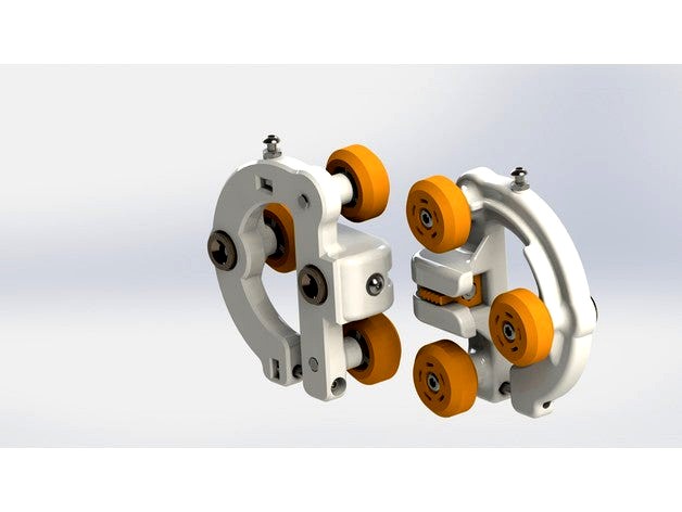
Here are two variants of a carriage adapted to slide along a 20x20 V-Slot type aluminium profile. The moves are controlled by a GT2 belt whose tension is adjusted by the tensioner. The connection with the rods connected to the effector is provided by two countersunk magnets spaced by 45mm between axes.
The displacement is controlled by a GT2 belt whose tension is adjusted by the tensioner. The connection with the rods connected to the end effector is provided by two spaced countersunk magnets 45mm between axes.
The magnetic effector with 45mm between-axle associated with these carriage can be found here : https://www.thingiverse.com/thing:2024371
I designed two versions of the carrier to test if there is a difference in print quality between the two models. I guess the variant with magnets on the centre of the carrier provides the best result. Indeed, the rods which connect the carriage to the effector exert constraints on the carriage, pushing them outwardly of the printer. More the points of application of forces (thus the magnets) are away from the centre of the carriage, and more the lever arm is important. Therefore, undesirable movements should be amplified with the carriage model having the magnet mountings on the top. It remains to see if the stresses exerted by the rods are sufficient to affect the print quality. . . Otherwise the advantage to deport the magnets up is that we gain 4cm print height.
Do not hesitate to make me your feedback by posting a comment.
NB: All necessary materials support are included in the design, no need to activate this feature in the slicer.
The assembly of a carriage has two printed parts :
a carriage
a tensioner
Hardware for one carriage :
3x Wheels:
1x wheel Wheel Type Solid V (tire + 2 x 625ZZ bearing + 1x M5 precision washer)
1x M5x25 screws (to fix the wheel)
1x M5 short washer
1x Home end stop adjustment screw :
1x M3x20 screw
2x M3 Nut
1x Belt tensioner :
1x M3x25 screw
1x M3 short Washer
1x M3 nut
1x Tightening on aluminium profile 20x20
1x M3x25 screw
1x M3 nut
2x countersunk D12 Magnets d4 e4.75
Preparation
Print and clean the two parts
Remove the print support material
Make sure all fits correctly
Assembly
No need to go into a long and boring description, it's mounted as show on the picture. :)
Voici deux variantes d'un chariot conçu pour se déplacer le long d'un profilé aluminium 20x20 de type V-Slot. Les déplacements sont pilotés par une courroie GT2 dont la tension est réglée par le tendeur. La liaison avec les tiges reliées à l'effecteur est assurée par deux aimants fraisés distants de 45mm entre axes.
L'effecteur magnétique d'entre-axe 45mm associé à ces chariots se trouve ici : https://www.thingiverse.com/thing:2024371
J'ai conçu deux versions de ce chariot pour vérifier s'il y a une différence de qualité d'impression entre les deux modèles. Je suppose que la variante avec les aimants au centre de du chariot offre le meilleur résultat. En effet, les tiges qui relient le chariot à l'effecteur exercent des contraintes sur le chariot, les repoussant vers l'extérieur de l'imprimante. Plus les points d’application des forces (donc les aimants) sont éloignés du centre du chariot et plus le bras de levier est important. Par conséquent, les mouvements indésirables devraient être amplifiés avec le modèle de chariot possédant les fixations d'aimants en haut. Reste à voir si les contraintes exercées par les tiges sont suffisantes pour affecter la qualité d'impression... Sinon l'avantage de déporter les aimants vers le haut est que l'on gagne 4cm de hauteur d'impression.
N'hésitez pas à me faire vos retours d’expérience en postant un commentaire.
NB : Les supports matériels nécessaires sont inclus dans le design, inutile d'activer cette fonctionnalité du slicer.
L'assemblage d'un chariot compte deux pièces imprimées :
un chariot
un tendeur
Quincaillerie pour un chariot :
3x Roues :
1x roue type Solid V Wheel (pneu + 2 roulements 625ZZ + rondelle de précision m5)
1x Vis M5x25 (pour fixer la roue)
1x rondelle courte M5
1x Réglage de butée Home :
1x Vis M3x20
2x Ecrou M3
1x Tendeur de courroie :
1x Vis M3x25
1x Rondelle courte M3
1x Ecrou M3
1x Serrage sur profilé alu 20x20
1x Vis M3x25
1x Ecrou M3
2x Aimants fraisés D12 d4 e4.75
Préparation
Imprimez et nettoyez les deux pièces
Supprimez les supports d'impression du chariot
Vérifiez que tout s’emboîte correctement
Assemblage
Inutile de rentrer dans une longue et ennuyeuse description, ça se monte comme sur la photo :)
--- English ---
Here are two variants of a carriage adapted to slide along a 20x20 V-Slot type aluminium profile. The moves are controlled by a GT2 belt whose tension is adjusted by the tensioner. The connection with the rods connected to the effector is provided by two countersunk magnets spaced by 45mm between axes.
The displacement is controlled by a GT2 belt whose tension is adjusted by the tensioner. The connection with the rods connected to the end effector is provided by two spaced countersunk magnets 45mm between axes.
The magnetic effector with 45mm between-axle associated with these carriage can be found here : https://www.thingiverse.com/thing:2024371
I designed two versions of the carrier to test if there is a difference in print quality between the two models. I guess the variant with magnets on the centre of the carrier provides the best result. Indeed, the rods which connect the carriage to the effector exert constraints on the carriage, pushing them outwardly of the printer. More the points of application of forces (thus the magnets) are away from the centre of the carriage, and more the lever arm is important. Therefore, undesirable movements should be amplified with the carriage model having the magnet mountings on the top. It remains to see if the stresses exerted by the rods are sufficient to affect the print quality. . . Otherwise the advantage to deport the magnets up is that we gain 4cm print height.
Do not hesitate to make me your feedback by posting a comment.
NB: All necessary materials support are included in the design, no need to activate this feature in the slicer.
The assembly of a carriage has two printed parts :
a carriage
a tensioner
Hardware for one carriage :
3x Wheels:
1x wheel Wheel Type Solid V (tire + 2 x 625ZZ bearing + 1x M5 precision washer)
1x M5x25 screws (to fix the wheel)
1x M5 short washer
1x Home end stop adjustment screw :
1x M3x20 screw
2x M3 Nut
1x Belt tensioner :
1x M3x25 screw
1x M3 short Washer
1x M3 nut
1x Tightening on aluminium profile 20x20
1x M3x25 screw
1x M3 nut
2x countersunk D12 Magnets d4 e4.75
Preparation
Print and clean the two parts
Remove the print support material
Make sure all fits correctly
Assembly
No need to go into a long and boring description, it's mounted as show on the picture. :)
Similar models
thingiverse
free

FTX KANYON DF4J connecteur rapide éclairage by PrintPat
...posés et maintenue avec une pointe de cyano.
pour la carrosserie le système est maintenue par de vis m3 tête fraiser avec écrous.
thingiverse
free

Effecteur magnetique pour HotEnd Merlin - Magnetic effector for Merlin HotEnd by CherHubert
...when in use, be sure to always ventilate it in order to avoid overheating and thus its deformation. (it's a slicer parameter)
thingiverse
free

Tendeur de Courroie Axe X Discoeasy 200 Dagoma by Petit_Homard_Breton
...fait que les fixations des roulements sont intégrées au tendeur. version de gilly_wings:https://www.thingiverse.com/thing:2018092
thingiverse
free

Porte aimant tulipe by ledjo
...optimise en passant un coup de papier de verre sur le bas de l'aimant et en mettant de la colle a l'interieur des petales
thingiverse
free

Cache avant pour D-Bot by gilly_wings
...ng.
this hides clips directly on the carriage fixing screws.
two versions, one simple and the other for the autolevelling system.
thingiverse
free

Tendeur de courroie X pour DiscoEasy200 by gilly_wings
... d'origine.
insérer une vis et un écrou m3 dans le tendeur
placer les roulements à l'aide d'un tube de styla à bille.
thingiverse
free

Support alimentation plateau chauffant by Demoniac
...lisées pour assembler le boitier sont de type m3 ainsi que deux boulons de type m4 avec rondelles pour fixer l'alimentation.
thingiverse
free

Support plateau Dagoma aimante reglable en hauteur by nicosky
...imprimer :
reglage hauteur bisot x4
reglage hauteur plot x4
pave aimant x2
capot serrage x2
chariot plateau x2
support plateau x2
thingiverse
free

support palpeur pour chariot Z de Z122 by rarnomix
...mprunté a erebius et j'ai utilisé quelques rondelles de 5 pour la détection. le bridage du palpeur se fait par une vis m3x16.
thingiverse
free

Evolution2 Prothese de main ( droite ) et gauche avec velcro by YAN-D
...es ronds en velcro ,possibilité de remplacer les aimants par du velcro....la version droite gauche ne convient que pour du velcro
Cherhubert
thingiverse
free
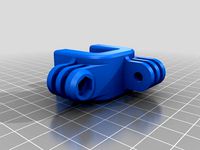
Petit serre-joint GoPro by CherHubert
...petit serre-joint gopro by cherhubert
thingiverse
mini serre-joint avec montages types gopro
mini clamp with gopro fixtures
thingiverse
free

GoPro HERO 2 Frame by CherHubert
...e
fr : boîtier conçues pour être imprimées sans supports matériels.
en : frame designed to be printed without material supports.
thingiverse
free

Poignée imitation volant en fonte by CherHubert
...née de meuble et bouton d'autoradio imitation volant en fonte.
modélisé avec fusion 360, source ici : https://a360.co/2vqg3xe
thingiverse
free

CHACRAS (CherHubert Amazing Case for Ramps-Arduino-Screen) for Lowrider2 Y mounting by WrightWells
...2 y mounting by wrightwells
thingiverse
changes location of the power input and adds holes to allow fitting to the y plate bolts
thingiverse
free

Support casque / helmet holder by CherHubert
...h :
variable tilt motorcycle helmet wall mount.
you will need a 6mm diameter threaded rod and two nuts to assemble the two parts.
thingiverse
free

Toupie - Fidget hand spinner by CherHubert
...:
1 x fidget spinner-corps.stl printed
2 x fidget spinner-bouton.stl printed
1 x 625 ball bearing (d16 d5 e5)
5 x balls about d16
thingiverse
free

Boitier Camera Pi V2 avec Leds IR by CherHubert
...v2 équipée de leds infrarouges.
si vous êtes aussi intéressé par le serre-joint de plateau qui se trouve sur la photo, il est ici
thingiverse
free

Support flechettes / Dart holder by CherHubert
...he photos), the darts are very close to each other, the center distance is 17.5mm
3x5, more spaced with a center distance of 20mm
thingiverse
free

Support écran / monitor stand by CherHubert
...pport dimension : 260x182 outside 204x123 inside, 100mm height
print duration : 32h33 with a 0.5mm nozzle and 0.3mm layers height
thingiverse
free

Toupie - Fidget hand spinner by CherHubert
....stl printed
2 x spinner-bouton.stl printed
1 x 625 ball bearing (d16 d5 e5)
2 x balls about d16
the black part was bomb-painted.
Chariot
turbosquid
$5

Chariot
... available on turbo squid, the world's leading provider of digital 3d models for visualization, films, television, and games.
3d_export
$10

Chariot 3D Model
...chariot 3d model
3dexport
chariot other kolesnica waggon telega
chariot 3d model zavhoz 4111 3dexport
3d_export
free

chariot 1
...chariot 1
3dexport
3d_ocean
$59

3D old cars and chariots
...d chariot 3d model 3d vehicle car chariot old car old chariot old vehicle vehicle
3d old cars and old chariots low and hight poly
3d_export
$25

Chariot 3D Model
...el
3dexport
chariot transport horse
chariot 3d model download .c4d .max .obj .fbx .ma .lwo .3ds .3dm .stl issevin 112361 3dexport
turbosquid
$25

Santa Chariot
... available on turbo squid, the world's leading provider of digital 3d models for visualization, films, television, and games.
turbosquid
$3

Mine chariot
... available on turbo squid, the world's leading provider of digital 3d models for visualization, films, television, and games.
turbosquid
free

Roman Chariot
... available on turbo squid, the world's leading provider of digital 3d models for visualization, films, television, and games.
turbosquid
$10

Chariot - Sumerian
...- sumerian for download as 3ds, lwo, obj, blend, dae, and stl on turbosquid: 3d models for games, architecture, videos. (1349655)
turbosquid
$10

Chariot - Assyrian
...- assyrian for download as 3ds, lwo, obj, blend, dae, and stl on turbosquid: 3d models for games, architecture, videos. (1349636)
Carriage
archibase_planet
free
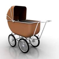
Carriage
...arriage
archibase planet
perambulator baby carriage pram
carriage n250908 - 3d model (*.gsm+*.3ds) for interior 3d visualization.
3d_export
free
carriage
...carriage
3dexport
old fashion carriage model, more files here:
turbosquid
$140
Carriage
...urbosquid
royalty free 3d model carriage for download as max on turbosquid: 3d models for games, architecture, videos. (1482052)
turbosquid
$25
Carriage
...urbosquid
royalty free 3d model carriage for download as max on turbosquid: 3d models for games, architecture, videos. (1285944)
3d_export
free
carriage
...carriage
3dexport
game cart
3d_ocean
$15
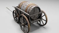
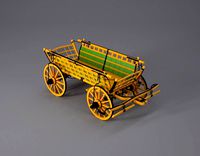
Barrel Carriage
...ieval oak old transport wheels wine wood
this model contains a barrel and a carriage. it is a medieval type of wood oak carriage.
turbosquid
$40
Carriage
...ty free 3d model carriage for download as obj, fbx, and blend on turbosquid: 3d models for games, architecture, videos. (1290094)
turbosquid
free
Carriage
...yalty free 3d model carriage for download as ma, obj, and fbx on turbosquid: 3d models for games, architecture, videos. (1239157)
3d_export
$5
Medieval carriage
...medieval carriage
3dexport
medieval carriage in fairy style
turbosquid
$58

Carriage
...d model carriage with scene for download as max, obj, and fbx on turbosquid: 3d models for games, architecture, videos. (1276262)