GrabCAD
Channel Slot
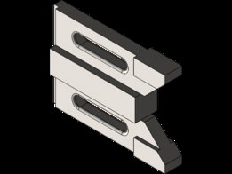
by GrabCAD
Last crawled date: 8 months ago
Mass = 1122.85 grams
Volume = 153814.99 cubic millimeters
Surface area = 32383.21 square millimeter
This project is in mm and the material is Cast Alloy Steel. At first, I sketched out the front view with the center rectangle, 100mm long and 25mm wide, corner rectangle along the top of the center rectangle, 130.50mm long and 35mm wide. Then found the midpoint the left side on a rectangle and placed a construction line of 95.5 mm, on which I constructed a centerpoint straight slot, 48mm long and 11mm wide, using the smart dimensions, I measured 30.5mm from the left side of the corner rectangle to the 1st slot point and then I made sure the measurements from the top line to the middle of the slot equals to 17.5mm. I connected a line to the open point of the construction line to the top of the corner rectangle, which should be 17.5mm from the construction line to the top of the corner rectangle. Then measure the new made line to the right side of the corner rectangle, which should be 35mm. I deleted the bottom right line of the corner of the rectangle, measured a 4mm extending from the center rectangle, top line. Then constructed a line, which is connected to the 4mm open point to the random placement of the ride side of the corner rectangle. I measured 45 degrees between the randomly constructed line and the line on the right of the corner rectangle. After the smart dimensions are placed, I used a trim entities to cut out the hanging line of the right side of the corner rectangle. There should be an automatic measurement of the 8.5mm on the top right side of the corner rectangle. I placed a line from the previously constructed line for the slot horizontally to the side on the angled line. Then I mirrored that top side to the bottom half. And last for the sketch, I measured 5mm from the left side of all rectangles and trimmed out everything that was inside.
Now for the 3D model, I extruded (mid plane) the center rectangle first, 25mm. Then I started another sketch on the front plane and using the converted entities and trim entities I picked the top and bottom corner rectangles and slots except the individual top right and bottom pieces (small rectangles with a 45 degree angle on the bottom right side of them), and extruded it to 12mm. Then I did the same for the rest. The small right-side rectangles extrude to 19mm, the last 5mm long piece is to 8.5mm. Then cut (from the front view) left side by 10mm deep and 5mm long. And finally, I applied 2mm fillet.
Similar models
grabcad
free

Fixture Block
...st part i needed to do was create an arc with a radius of 7.5mm on the mid point of the edge on the angled back side of the part.
grabcad
free

Pin Channel
...nd cut it 15mm deep. and finally, create a rectangle 35mm by 70mm, 100mm away from the top left of the figure, 15mm deep as well.
grabcad
free

Tapered Pin Slot
...80 by r5 and extrude cut it through all. i finally make the cut of rectangle from a sketch 25x40 and cut through the whole model.
grabcad
free

stc_cad_cs
...sure the back side has the middle bas up to the end of the thin line. lastly fillet the slots on both sides by 2mm and that’s it.
grabcad
free

Channel Slot
...ugh all-both and you are done.
mass: 1122.85 grams
volume: 153815.28 cubic millimeters
surface area: 32383.21 square millimeters
grabcad
free

Latch
... line should come out to be 6.17 mm. extrude the form 45mm wide and the apply a 5mm fillet on the edge near the 29 radius circle.
grabcad
free

Plate
...rds, use circular pattern to create 9 of those parts around the circle (make sure to include all features and faces of the part).
grabcad
free

Channel Slot
...e rest of my drawing.
>lastly, i changed the material to cast alloy steel and measured the mass. i had to re-evaluate my mass.
grabcad
free

Sanding brush for feet - 341
...jesql
================================
subscribe, comment, give to like and share.
thank you very much!
greetings.
arpsolidworks
grabcad
free

Channel Slot
...ure all my measurements were on point, i then inserted an extruded cut on the back left side of the model, making it 10mm by 5mm.
Slot
grabcad
free

slot
...slot
grabcad
slot
grabcad
free

Channel Slot
...channel slot
grabcad
channel slot
grabcad
free

Slotted Box
...slotted box
grabcad
slotted box
grabcad
free

excercise Slot
...excercise slot
grabcad
excercise slot
grabcad
free

Slot car
...slot car
grabcad
slot car
grabcad
free

channel slot
...channel slot
grabcad
channel slot
grabcad
free

Slotted mechanisem
...slotted mechanisem
grabcad
slotted mechanisam
grabcad
free

FORSETI_PERFIL_20x20_V-SLOT
...forseti_perfil_20x20_v-slot
grabcad
forseti_perfil_20x20_v-slot
grabcad
free

V-Slot
...v-slot
grabcad
v-slot
grabcad
free

Slotted Block
...slotted block
grabcad
slotted block
Channel
grabcad
free

Channel
...channel
grabcad
spl
grabcad
free

Channel
...channel
grabcad
ftc part
grabcad
free
Channel Slot
...channel slot
grabcad
channel slot
grabcad
free

Pin Channel
...pin channel
grabcad
a pin channel
grabcad
free

Channel Jig
...channel jig
grabcad
channel jig
grabcad
free

pin channel
...pin channel
grabcad
pin channel
grabcad
free

pin channel
...pin channel
grabcad
pin channel
grabcad
free
channel slot
...channel slot
grabcad
channel slot
grabcad
free

pin channel
...pin channel
grabcad
pin channel
grabcad
free

Pin Channel
...pin channel
grabcad
pin channel