Thingiverse
Cart Pulling Robot
by Thingiverse
Last crawled date: 4 years, 2 months ago
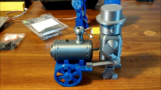
This is another walking toy design. This one pulls a cart and uses a similar construction as a previous design I did.https://www.thingiverse.com/thing:4020131
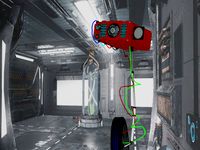
It has a kind of steam punk look with a wooden cart and boiler.
The pivots are made from T-pins I bought at Wal_Mart. They have a 1 mm diameter. The motor is a commonly available 6V 100 rpm N20 gearmotor powered by a 150 mah lipo. The batteries were purcased from Banggood and came with a charger and the small jumper cables. You need to use one of the charging cables to hook the battery to the motor through the switch. The switch is from a tea light. The battery is just stuffed in the boiler. The switch is on top of the boiler. You can access the connector for the battery to recharge it by removing the back of the boiler which is held on by a screw.
Parts:
6V 100 rpm N20 gearmotor
1/8 inch or 3mm dia X 32 mm long rod. I used 1/8 inch brass brazing rod.
2mm X 8mm self tapping screw
150 mah lipo and connectorhttps://www.banggood.com/5PCS-Eachine-E010-3_7V-150mAh-Battery-RC-Quadcopter-Spares-Parts-p-1081736.html?rmmds=myorder&cur_warehouse=CN
switch from a tea light
1mm diameter T-pins
heat shrink tubing
super glue and hot glue
Build notes:
Make sure to remove all burrs, bumps and anything else that might interfere with free movement. I use a small rat tailed file for inside holes and gear teeth, but a hobby knife would work. A sheet of 200 grit sandpaper on a flat surface works for flat parts. A nail file board also works well. There are several 3d printed threaded parts. The internal threads should be cleaned out with a 6mm X 1mm tap. If you don't have a tap you may be able to use a 6mm bolt with a groove dremeled into it. I haven't had to use a die to clean up the external threads. Run a tap through the threaded holes in the frame and cart.
It's best to first wire the motor up with the switch and battery so you can test run it at every stage of assembly. You need the connector on the charger jumper so you can wire it to the switch and motor. Make sure you use heat shrink tubing to avoid shorts. These little batteries have a lot of energy in them and shorting them could cause a fire.
After you get the wiring done, put the motor gear on the motor. If it's loose, it will still work but you can use a drop of hot glue if you like. Then slide the motor into the frame from the shaft side.
The gear and crank assembly is built around an 1/8 inch brass rod but a 3 mm would probably work. The length should about 32 mm. I was able to mount the shaft gear and cranks by driving the rod through them with a small hammer. A block of wood with a hole just a little larger than the shaft diameter will allow you to lay the gear or crank on the block and drive the shaft through it. You may have to use a drill if the holes are too small or super glue if they are too big. The cranks have a line on them. The line goes to the outside and the cranks should be lined up with one crank pointing up and the other crank pointing down so the toy will walk. When your finished there should be a little clearance between the crank and the frame on each side. There should also be clearance between the shaft gear and the frame. The shaft should rotate freely. Use a 2mm X 8mm screw to mount the clamp to the frame. Check the shaft for binding. Now you can slide the motor up until the gears mesh. Turn on the motor and adjust it's position until it's running free without skipping teeth. A little hot glue may help hold this position.
All the screws used in the build are 2 mm X 8 mm. The screws mount the main body and arms to the frame. Another screw is used to hold the motor clamp part to the frame. The clamp holds the shaft, crank, gear assembly in place. There are 4 screws holding the boiler to the cart. They go through the pedestals. The arms use hex pins to key them to the main body. The hex pins are super glued to the arms. After the arms are mounted to the main body they are connected to the cart with 2 more screws. The square hole in front of the boiler allows the switch to be passed through into the boiler. There is a one layer sacrificial bridge in the hole that needs to be cut away with a hobby knife.
The T-pins used for the pivots are held by friction to the parts upper_legs and foot. The mating holes are designed with more clearance so the pins pivot freely. After inserting the pins through the parts they are cut off flush with side cutters. The pictures at the end of the video show the assembly sequence.
The 3 parts of the head are super glued together and then to the main body.
Print instruction:
The parts with a _X2 on the end of the filename require 2 copies be printed for the build. All the other parts only need 1 copy. The boiler back cover needs supports. All the small threaded parts, cranks and gears are printed with 100% infill. The rest use 20%. I sliced it with Cura 4.4 so you can use per model settings to print the whole thing at once. I printed it at .15mm layer height.
Here's a video of the toy with some details. The video has a lot of assembly photos at the end.https://youtu.be/JD8gFildHE0
If I missed a file or some other detail, let me know and I'll try to fix it.
Good luck,
Rick
Similar models
thingiverse
free

Walking Toy Robot
...nprinter at .15mm layer height.
if i missed a file or some other detail, let me know and i'll try to fix it.
good luck,
rick
thingiverse
free

Parametric Stepper Motor Crank for 1/4" or 6.25mm shaft by mredmon
...shers threaded into the handle. you might need to tap the handle but i was able to directly thread the m3 screw into the handle.
thingiverse
free

Watch Winder Geared by JohoJoho
...infos will make this watch winder work for you, since i think the design is really neat.
feel free to ask if anything is unclear.
thingiverse
free

Bullzeye Clock Remix by Legedus83
...les for small screws to connect each other from the back frame. the hex insert part never really fit into it's hole properly.
grabcad
free

Crank Shaft Assembly
...crank shaft assembly
grabcad
crank shaft assembly with crank pin.
48.5 mm stroke
needs a lot of work.
thingiverse
free

Wheel hub - 12mm hex to 5mm by nshaver
...ve gotten much better results by just adding a small hole into the part where i want the threads and then thread them with a tap.
thingiverse
free

MRC/Academy GV2 Front Arm by rcnand
...crews in the kit are self tapping screws so you can either use them as-is or tap and use a m2 screw with a washer/oversized head.
thingiverse
free

Nodemcu ESP8266 SSD1306 Desktop Assistant
...u should glue the parts.
i use two 18650 batteries with holder, and there is a hole for a switch to power him up on the backside.
thingiverse
free

Stepper Shaft Adapter by ahmlol
...rod and two machine-screws as tighteners for the shaft.
comment your improvement ideas or contact me if you need the cad-files :)
thingiverse
free

TRONXY X5 Alternative Z Limit Switch Assembly by BTNZ
...tap on the back for the m3x20 screws to screw into but you could easily drill out the holes for use as clearance holes with nuts.
Pulling
3ddd
$1

Muuto Pull Lamp
...muuto pull lamp
3ddd
muuto , pull lamp
model of pull lamp, designed by muuto
3d_ocean
$24

Pull-down Machine
...n equipement gym gymnastic indoor machine pull pull-down silver sport workout
3d model of black and silver pull-down gym machine.
turbosquid
$19

Pull high
...rbosquid
royalty free 3d model pull high for download as ige on turbosquid: 3d models for games, architecture, videos. (1338664)
turbosquid
$9

Pull Rod
...urbosquid
royalty free 3d model pull rod for download as c4d on turbosquid: 3d models for games, architecture, videos. (1343200)
3ddd
$1

Pull and Bear Sneakers
...pull and bear sneakers
3ddd
обувь , кроссовки
pull and bear sneakers
turbosquid
$38

Pull Station
... free 3d model pull station for download as max, obj, and fbx on turbosquid: 3d models for games, architecture, videos. (1290796)
turbosquid
$20

Pouf with pulls
...ee 3d model pouf with pulls for download as max, obj, and fbx on turbosquid: 3d models for games, architecture, videos. (1186069)
turbosquid
$24

Pull Toy
... available on turbo squid, the world's leading provider of digital 3d models for visualization, films, television, and games.
turbosquid
$8

Pull Saw
... 3d model pull saw for download as ma, max, obj, c4d, and fbx on turbosquid: 3d models for games, architecture, videos. (1178540)
turbosquid
$1

Pull Switch
...model pull switch for download as max, 3ds, fbx, obj, and dxf on turbosquid: 3d models for games, architecture, videos. (1649377)
Cart
archibase_planet
free

Cart
...cart
archibase planet
cart small cart hand-cart
cart f1823 - 3d model for interior 3d visualization.
archibase_planet
free

Cart
...cart
archibase planet
cart small cart hand-cart
cart f1507 - 3d model for interior 3d visualization.
archibase_planet
free

Cart
...cart
archibase planet
library cart small cart hand-cart
library cart - 3d model for interior 3d visualization.
archibase_planet
free

Cart
...
archibase planet
cart trolley small cart hand-cart handcart
cart n220411 - 3d model (*.gsm+*.3ds) for interior 3d visualization.
archibase_planet
free

Cart
...cart
archibase planet
cart trolley small cart
cart n060712 - 3d model (*.gsm+*.3ds) for interior 3d visualization.
archibase_planet
free

Cart
...cart
archibase planet
cart shopping cart trolley
cart n250113 - 3d model (*.gsm+*.3ds) for interior 3d visualization.
archibase_planet
free

Cart
...cart
archibase planet
cart hand-cart dinner wagon handcart
cart - 3d model (*.gsm+*.3ds) for interior 3d visualization.
archibase_planet
free

Cart
...cart
archibase planet
small cart hand-cart handcart
cart fe0876 - 3d model (*.gsm+*.3ds) for interior 3d visualization.
3d_export
$6

the cart
...the cart
3dexport
a cart for animals or people.
3d_export
$10

The cart
...the cart
3dexport
cart with logs. divided into parts
Robot
3d_ocean
$20

Robot
...robot
3docean
character metal robot robot robotic white
robot model for 3dsmax 2009 and greater
3d_ocean
$45
Robot
...robot
3docean
fighing machine robot
a fighting robot from the scrapyard.
3d_ocean
$18
Robot
...robot
3docean
machin robot science fiction
high poly robot.
3d_export
$7
Robot
...robot
3dexport
robot
3d_export
$5
robot
...robot
3dexport
robot
3d_export
free

Robot
...robot
3dexport
robot
turbosquid
$10

Robot/ Alien Robot
...
royalty free 3d model robot/ alien robot for download as max on turbosquid: 3d models for games, architecture, videos. (1442828)
3d_export
$5

robot
...robot
3dexport
robot in blender
3ddd
$1

robot
...robot
3ddd
робот
robot
3ddd
$1

Robot
...robot
3ddd
робот
robot