Thingiverse
Caliper Data Connector by JMadison
by Thingiverse
Last crawled date: 3 years, 1 month ago
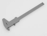
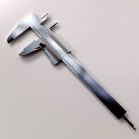
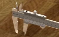
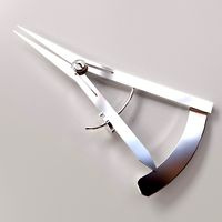
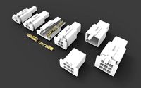
This is a data connector for some of the Chinese calipers and tire depth gauges. If the button layout is the same as shown in the pictures, this connector will probably work.
For step by step instructions for building this connector cable for the SMD caliper data interface board, visit: https://www.instructables.com/id/Caliper-Data-Interface/
Note that as of 03-APR-2019 there is a version 2 of this connector described at the end of this summary.
Version 1
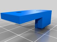
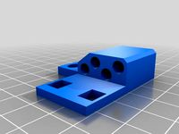
Print both STLs at 0.1mm layer height, 20% infill, no support, with just a skirt, no brim (if you print with a brim it’s a pain to cleanup)
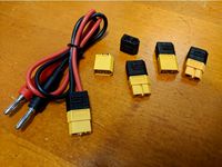
For wire I used 26AWG 1.27mm pitch flat cable. This is the ubiquitous “jumper cable” product you get with Dupont connectors already attached.
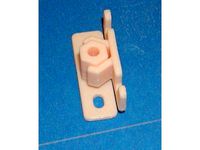
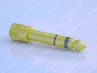
For this connector you need 4 conductors, any color. Strip 2cm of insulation off one end as shown in the pictures. Apply solder to the first 15mm of wire from the tip to stiffen the wire. After cleaning up the print of Connector.stl, use a 1.5mm drill bit to enlarge the exit holes and to remove any material in between. The goal is to be able to insert all 4 insulated conductors bonded together as shown in the picture. Using the ConnectorNoHandle print, place the 4 soldered conductors in the 1.5mm on center cuts and use this as a guide to insert the wires into the connector with a handle. After verifying that you’re able to insert the insulated cable into the exit holes approximately 5mm, withdraw the wire till the bare wires are exposed. Apply some plastic epoxy to the insulation and reinsert the wires. Put the assembly aside and wait for the epoxy to cure. Once cured fold the 4 wires around the end of the connector, cleaning up the soldered ends as needed.
The data and clock signals coming from the caliper are 1.5v. I’ve included a simple circuit to level shift to 5V (VCC in the circuit). The only reason I used a comparator to do the level shifting is that that’s what I had on hand. Use whatever you have available to do the unidirectional level shifting. Note that you DO NOT want a bidirectional circuit.
I’ve also included a simple Arduino sketch so you can see the raw data coming from the caliper.
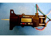
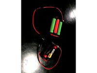
The pin assignments, as shown in the pictures:
Green - GND
Blue - DATA
Purple - CLOCK
Gray - +1.5V
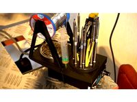
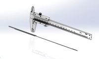
I chose a tire gauge because it’s cheap (~US$4), and it meets the future use as a height data probe for a project I’m starting. If you attach a low force spring to keep the caliper probe extended, then attach the tire gauge to a servo, Vwa-lah, you have a really inexpensive data probe.
https://www.aliexpress.com/item/WSFS-Hot-Digital-depth-gauge-caliper-tread-depth-gauge-LCD-Tyre-tread-gauge/32775295632.html?spm=a2g0s.9042311.0.0.FIUyIk
Note that the price varies. When I bought mine it was offered for less than US$4. I bought a few more at another site for a little less. If the unit body looks like the gauge/caliper in the picture, it’s probably OK.
Update 11-AUG-2017: Modified ConnectorNoHandle.stl so that insulated wires can be epoxied the same as the connector with a handle.
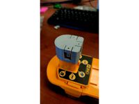
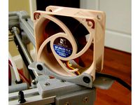
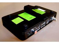
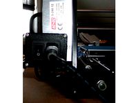
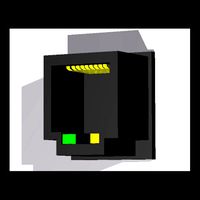
Update 22-AUG-2017: I uploaded a picture of my test setup. The caliper is being powered by a DC-DC regulator (shown in the beige box) to supply 1.5V. The data is being monitored by an ATTiny85, turning the caliper into an I2C device. Whenever the value changes, the ATTiny85 sets a signal wire high. The Arduino Pro mini, acting as the I2C master, then requests 3 bytes from the ATTiny85 via I2C. The ATTiny85 then resets the signal wire. If change notification isn’t needed, the master can, at any time, request the latest value from the ATTiny85 via I2C. If anyone is interested in the Arduino projects for what’s described in this update, let me know and I’ll upload them
Update 28-OCT-2017: See https://www.thingiverse.com/thing:2612218 for an implementation example that uses an I2C interface.
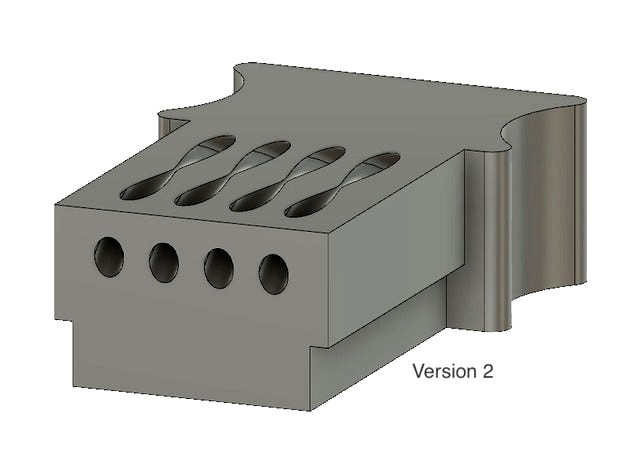
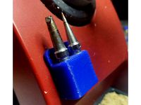
Update: 03-APR-2019
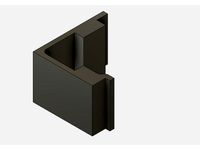
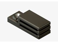
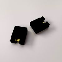
Version 2
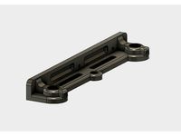
I’ve added an updated connector. The improvements are:
doesn’t have any sharp bends in the contact wires.
forces the contact wires above the plane of the connector.
contact ends are held in place
Downside:
like the original connector, you still need to use a rubber band to keep the connector in place.
cleanup is a bit more difficult than version 1.
Print at 100% fill, no support with just a skirt.
Because it’s such a tiny print I had to slow down the print and travel speed to 30mm/s, 60mm/s. (depending on the accuracy of your printer.)
The hole sizes are 1.4 and 0.8mm. I used a cheap set of PCB drill bits to clean out the holes.
( https://www.aliexpress.com/item/10PCS-package-tungsten-drill-bit-0-6-1-5mm-spiral-hand-drill-woodworking-tools-CNC-drill/32749247271.html )
Strip about 2.5cm of insulation and apply solder to stiffen the wire.
Use PCB cleaner to remove the flux residue.
Trim the soldered ends by removing the last 2mm.
Using the holes at the connector tip as a spacing guide, insert the connector wires and fish the wires through to the tip.
Push and pull the connector wires into the connector shell until the insulation is seated about 3 to 4mm into the shell.
Pull the insulated wires back until you see the bare wires.
Apply plastic epoxy
Push and pull the insulated wires into the housing.
Set aside and wait for the epoxy to cure.
Once cured, trim the ends of the connector wires flush with the connector tip.
For step by step instructions for building this connector cable for the SMD caliper data interface board, visit: https://www.instructables.com/id/Caliper-Data-Interface/
Note that as of 03-APR-2019 there is a version 2 of this connector described at the end of this summary.
Version 1
Print both STLs at 0.1mm layer height, 20% infill, no support, with just a skirt, no brim (if you print with a brim it’s a pain to cleanup)
For wire I used 26AWG 1.27mm pitch flat cable. This is the ubiquitous “jumper cable” product you get with Dupont connectors already attached.
For this connector you need 4 conductors, any color. Strip 2cm of insulation off one end as shown in the pictures. Apply solder to the first 15mm of wire from the tip to stiffen the wire. After cleaning up the print of Connector.stl, use a 1.5mm drill bit to enlarge the exit holes and to remove any material in between. The goal is to be able to insert all 4 insulated conductors bonded together as shown in the picture. Using the ConnectorNoHandle print, place the 4 soldered conductors in the 1.5mm on center cuts and use this as a guide to insert the wires into the connector with a handle. After verifying that you’re able to insert the insulated cable into the exit holes approximately 5mm, withdraw the wire till the bare wires are exposed. Apply some plastic epoxy to the insulation and reinsert the wires. Put the assembly aside and wait for the epoxy to cure. Once cured fold the 4 wires around the end of the connector, cleaning up the soldered ends as needed.
The data and clock signals coming from the caliper are 1.5v. I’ve included a simple circuit to level shift to 5V (VCC in the circuit). The only reason I used a comparator to do the level shifting is that that’s what I had on hand. Use whatever you have available to do the unidirectional level shifting. Note that you DO NOT want a bidirectional circuit.
I’ve also included a simple Arduino sketch so you can see the raw data coming from the caliper.
The pin assignments, as shown in the pictures:
Green - GND
Blue - DATA
Purple - CLOCK
Gray - +1.5V
I chose a tire gauge because it’s cheap (~US$4), and it meets the future use as a height data probe for a project I’m starting. If you attach a low force spring to keep the caliper probe extended, then attach the tire gauge to a servo, Vwa-lah, you have a really inexpensive data probe.
https://www.aliexpress.com/item/WSFS-Hot-Digital-depth-gauge-caliper-tread-depth-gauge-LCD-Tyre-tread-gauge/32775295632.html?spm=a2g0s.9042311.0.0.FIUyIk
Note that the price varies. When I bought mine it was offered for less than US$4. I bought a few more at another site for a little less. If the unit body looks like the gauge/caliper in the picture, it’s probably OK.
Update 11-AUG-2017: Modified ConnectorNoHandle.stl so that insulated wires can be epoxied the same as the connector with a handle.
Update 22-AUG-2017: I uploaded a picture of my test setup. The caliper is being powered by a DC-DC regulator (shown in the beige box) to supply 1.5V. The data is being monitored by an ATTiny85, turning the caliper into an I2C device. Whenever the value changes, the ATTiny85 sets a signal wire high. The Arduino Pro mini, acting as the I2C master, then requests 3 bytes from the ATTiny85 via I2C. The ATTiny85 then resets the signal wire. If change notification isn’t needed, the master can, at any time, request the latest value from the ATTiny85 via I2C. If anyone is interested in the Arduino projects for what’s described in this update, let me know and I’ll upload them
Update 28-OCT-2017: See https://www.thingiverse.com/thing:2612218 for an implementation example that uses an I2C interface.
Update: 03-APR-2019
Version 2
I’ve added an updated connector. The improvements are:
doesn’t have any sharp bends in the contact wires.
forces the contact wires above the plane of the connector.
contact ends are held in place
Downside:
like the original connector, you still need to use a rubber band to keep the connector in place.
cleanup is a bit more difficult than version 1.
Print at 100% fill, no support with just a skirt.
Because it’s such a tiny print I had to slow down the print and travel speed to 30mm/s, 60mm/s. (depending on the accuracy of your printer.)
The hole sizes are 1.4 and 0.8mm. I used a cheap set of PCB drill bits to clean out the holes.
( https://www.aliexpress.com/item/10PCS-package-tungsten-drill-bit-0-6-1-5mm-spiral-hand-drill-woodworking-tools-CNC-drill/32749247271.html )
Strip about 2.5cm of insulation and apply solder to stiffen the wire.
Use PCB cleaner to remove the flux residue.
Trim the soldered ends by removing the last 2mm.
Using the holes at the connector tip as a spacing guide, insert the connector wires and fish the wires through to the tip.
Push and pull the connector wires into the connector shell until the insulation is seated about 3 to 4mm into the shell.
Pull the insulated wires back until you see the bare wires.
Apply plastic epoxy
Push and pull the insulated wires into the housing.
Set aside and wait for the epoxy to cure.
Once cured, trim the ends of the connector wires flush with the connector tip.
Similar models
thingiverse
free
Digital Cailper Plug by noteasy2
...software:
it can be download from other designer as shown in the link below.https://github.com/makingstuffchannel/digitalcalipers
thingiverse
free
Wire end trap connector and mount by boutrous
...wire end trap connector and mount by boutrous
thingiverse
a wire trap for 4 conductor soldered connections.
thingiverse
free

Caliper Data Connector by CactiFantastico
... between the pins.
the fusion models use user parameters for most of the geometry so holes and other sizes can be easily changed.
thingiverse
free
Using a Cheap Tire Gauge as a Probe by JMadison
...etest.ino demos the caliper and byj48 classes.
caliperi2ctest.ino is a subset of probetest.ino that only demos the caliper class.
thingiverse
free
XT60 Connector Strain Relief by keoni29
...h an insulation diameter up to 4 mm / 14awg
multi cable - this accepts a 2-conductor cable with an insulation diameter up to 3 mm
thingiverse
free
Soldering Iron Tip Holder by isakh1
...5.5mm, you can drill it larger if needed.
this is for a magnum soldering iron
i sprayed the solder station with red enamel paint.
thingiverse
free

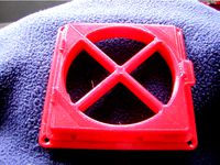
Skyzone Fan Button by Naralex
...e
solder as shown in the picture. we glue to the mask. we use!
suitable for these mask: https://www.thingiverse.com/thing:1255710
thingiverse
free
Ryobi Battery Connector Clip for Charging by projek_01
...tive terminal to the back terminal with a 1.2k ohm resistors to enable charging. please perform and use at your own risk.
thanks!
thingiverse
free
18650 Battery Holder/Sled x1,2,3,4 by ScottieD369
...gative(-) side of battery and spring get hot. if case then go back to tab,tab system. (i will make a set of those in future post)
thingiverse
free
solder iron and tip holder by lordleuter
...you like, or add features.
this is a stand for the tips and solder wire reel.
i have put it on my solder station for ease of use.
Jmadison
thingiverse
free
2020 Extrusion Cable Clip by JMadison
...trusion cable clip by jmadison
thingiverse
simple cable clip used to keep cables in place when running through a 2020 extrusion.
thingiverse
free
Flat Cable Mounting Clip by JMadison
...clip by jmadison
thingiverse
used to secure two 10 conductor flat cables.
uses a single m3 flathead screw.
print without support
thingiverse
free
60mm Fan mount by JMadison
...an. no grill, only mounts to one side.
the fan mounting holes use 5mm fan screws. the 2 other mounting holes are for m3 screws.
thingiverse
free
DIRECTV Genie mini mounting bracket by JMadison
...genies and only the new model we got this year has this receptacle. the holes on the wall bracket are for #6/m3 flathead screws.
thingiverse
free
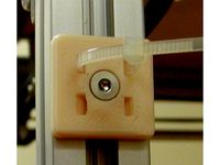
2020 Extrusion Cable Tie Mounts by JMadison
...hese are designed for cable ties less than 3mm wide.
the hole is for m3 flathead screws.
these should be printed without support.
thingiverse
free
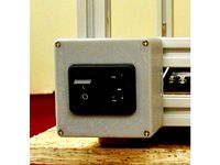
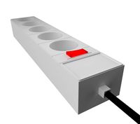
UM2 Clone Power Switch Box by JMadison
...elf tapping flathead screws (other sizes will probably work)
snap in switch+receptacle: http://www.ebay.com/itm/like/221725745452
thingiverse
free
ABS Fume filter by JMadison
...strong fan to push air through the larger capacity version. i found a 67cfm fan (or so it claims). i'll see how it performs.
thingiverse
free
Anet A8 Switch Box by JMadison
...ck nuts (or regular and use locktite)
(2) m3 nuts
other:
i didn't remove the power supply to take the photos, i have a spare.
thingiverse
free
False Front Cabinet Clip by JMadison
...e project i’m building i needed 16 of them and i’m too cheap to buy them. this version is slightly less beefy than the original.
thingiverse
free
Ultimaker2 Clone Gantry Z Axis Top Remix by JMadison
... also makes it easier to ream the 12mm holes because the holes go all the way through.
the locking screws are m3 x 8 button head.
Caliper
turbosquid
$7
CALIPER
...
royalty free 3d model caliper for download as stl and sldas on turbosquid: 3d models for games, architecture, videos. (1249938)
3d_export
$5
caliper
...caliper
3dexport
turbosquid
$15
Caliper
...ree 3d model caliper for download as blend, obj, fbx, and dae on turbosquid: 3d models for games, architecture, videos. (1653770)
turbosquid
$79
Caliper
... available on turbo squid, the world's leading provider of digital 3d models for visualization, films, television, and games.
turbosquid
$20
Caliper
... available on turbo squid, the world's leading provider of digital 3d models for visualization, films, television, and games.
3d_export
$15
Caliper 3D Model
...caliper 3d model
3dexport
caliper paquimetro dimension dimens??o
caliper 3d model tlsurf 21469 3dexport
turbosquid
$5
Vernier Caliper
...lty free 3d model vernier caliper for download as 3ds and obj on turbosquid: 3d models for games, architecture, videos. (1604280)
turbosquid
$40
Vernier Caliper
...ee 3d model vernier caliper for download as 3ds, max, and obj on turbosquid: 3d models for games, architecture, videos. (1298113)
turbosquid
$15
Vernier caliper
... 3d model vernier caliper for download as ige, obj, and sldas on turbosquid: 3d models for games, architecture, videos. (1227110)
turbosquid
$15
Castroviejo Caliper
... castroviejo caliper for download as blend, obj, fbx, and dae on turbosquid: 3d models for games, architecture, videos. (1649701)
Data
turbosquid
$3
Data cylinder
...quid
royalty free 3d model data cylinder for download as stl on turbosquid: 3d models for games, architecture, videos. (1333495)
3d_export
free

Olar Data Armchair
...olar data armchair
3dexport
olar data armchair
turbosquid
$9

DATA black coin
...id
royalty free 3d model data black coin for download as max on turbosquid: 3d models for games, architecture, videos. (1495567)
turbosquid
$9

DATA gold coin
...uid
royalty free 3d model data gold coin for download as max on turbosquid: 3d models for games, architecture, videos. (1495565)
3d_export
$35
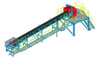
Conveyor data 3D Model
...conveyor data 3d model
3dexport
conveyors
conveyor data 3d model robertmelinda 83052 3dexport
turbosquid
$85

Dubai City 3d model with extra data August 2020 GIS data
...nload as c4d, c4d, c4d, dae, dxf, 3ds, c4d, obj, fbx, and stl on turbosquid: 3d models for games, architecture, videos. (1600663)
turbosquid
$60

Chinese MSGothic set1to21 data
...free 3d model chinese msgothic set1to21 data for download as on turbosquid: 3d models for games, architecture, videos. (1216976)
turbosquid
$9

DaTa eXchange black coin
...ty free 3d model data exchange black coin for download as max on turbosquid: 3d models for games, architecture, videos. (1495575)
turbosquid
$9

DaTa eXchange gold coin
...lty free 3d model data exchange gold coin for download as max on turbosquid: 3d models for games, architecture, videos. (1495569)
3d_export
$5

Kingston Data Traveler 3D Model
...kingston data traveler 3d model
3dexport
kingston data traveler 3d model shasiru 7868 3dexport
Connector
turbosquid
$5
Connector
... available on turbo squid, the world's leading provider of digital 3d models for visualization, films, television, and games.
turbosquid
$2
Connector
... available on turbo squid, the world's leading provider of digital 3d models for visualization, films, television, and games.
3d_export
$5
Connector 3D Model
...connector 3d model
3dexport
connector штекер 3d
connector 3d model manch111 83121 3dexport
3d_export
$14
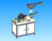
connector production equipment
...connector production equipment
3dexport
connector production equipment
3d_export
$10

connector xt60
...e designing, and will help save your precious time. the scale of the model is 1:1. the dimensions are for reference in the image.
turbosquid
free
Audio connectors
...del audio connectors for download as obj, fbx, blend, and dae on turbosquid: 3d models for games, architecture, videos. (1424706)
3d_export
$20
car connectors dj70
...quot; connector 9-pin "dj7091a-2.8-11/21" terminal (male) "dj611-2.8" terminal (female) "dj622-2.8"
turbosquid
$30

Cinch connector
... available on turbo squid, the world's leading provider of digital 3d models for visualization, films, television, and games.
turbosquid
$15
Jumper Connector
...umper connector for download as 3ds, obj, fbx, blend, and dae on turbosquid: 3d models for games, architecture, videos. (1494917)
turbosquid
$15
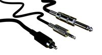
RCA Connector
...l rca connector for download as 3ds, obj, fbx, blend, and dae on turbosquid: 3d models for games, architecture, videos. (1376648)