Thingiverse
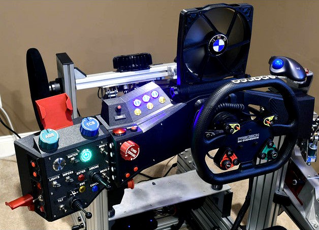
Button Box System for SimLab Vertical mount by RCHeliGuy
by Thingiverse
Last crawled date: 3 years, 3 months ago
1/12/2021 Added a Replay Binnacle V4 that is 2mm taller to accommodate 2 additional buttons and added 5mm holes for magnets for them. Added Stop Replay and Slow Motion Labels in my button box label project.
1/12/2021 Updated the SideLeftButtonPanel to a V4 to keep the threaded insert hole from showing through.
1/7/2021 Updated Replay Binnacle with 8mm hole for fan 12V plug. Updated Wiring Enclosure Cover with larger 12V hole.
1/4/2021 Added many pictures to help with assembly. Added ribbon extension cables. Added parts for optional fan at bottom.
Note: The pictures showing the wiring enclosure section has multiple cuts with a hot knife to make it fit and to give the replay binnacle additional space for wiring. The files have been updated with those changes. The Wiring enclosure pictures show overhang above the vertical profile. That overhang has been removed from the files so that a person who has their wheel set lower than mine would not have a problem.
Another person is having one printed up right now and I should learn what instructions and images need to be added to help make this an easier process.
1/3/2021 I just reorganized this into Fusion 360, STL pairs and removed the gcode and PrusaSlicer files that only confused things. I backfilled a couple missing files.
Note: This currently requires that the front of your Vertical mount be 50mm in front of the vertical profile supports for clearance at the top and bottom. There is a picture with a red arrow showing where this would be an issue.
I've included a Bill of Materials spreadsheet for what I have in my box. It is about 95% complete. Please think this project through before starting. I've been focusing on this for weeks and do not have comprehensive instructions.
Update planned: I'm planning to drill a hole in the Replay binnacle after my 12V connector hardware arrives on 1/5/2021. I'll update the associated files after I make sure I have it positioned properly.
Magnetic Labels are still in process.
Have included the Fusion 360 files so people can modify sections to their own liking.
Warning!! The wiring in this is dense and it will take patience especially for the wiring enclosure. The wiring will take time and securing the 7 M3 bolts at the back of the wiring enclosure with full wiring in place will be a bit challenging.
In some cases there are definite assembly order issues, so you may find that you need to remove something to get something else screwed down.
It may make sense to either use a glue gun or some other way to secure the magnets to the backs of the panels.
I also made sure to use a master label to ensure all of the polarities matched. The magnets are all pointing the exact same way so the labels can be put anywhere.
I've found that I sometimes need to drill holes that are printed vertically.
I also have found a hot knife can be helpful if you have a clearance issue. I have tried to update the files to take any issues I found into account.
I'm using a small chisel to clear supports where panels meet together. I have small reliefs in the corners of the panels so a chisel can completely clear a corner.
This is a project for a maker who has tools on hand and can work with things.
I found I needed a small ball head allen wrench for the M3 bolts.
This is a none trivial project. There are large print volumes. I've found using a brim and an enclosure helps reduce chances of warping on the larger prints.
The key features are the following:
Clamps directly to the SimLab Vertical Mount plate.
Has modular wiring so that each panel or part can be wired up independently and then plugged in using a ribbon cable.
Magnetic Labels for easy reassignment using 5x2mm magnets.
Tactile ridges and edges to easily find controls while in VR
Peripheral:
HMD hangar using M5 socket head bolts
Phone holder for Samsung Galaxy 8 with cover using M5 socket head bolts.
Also uses : Button Box Ribbon cable 8P / 16P / 20P 2.54 head connector mount
Parts published as I "complete" them.
Unless you sees a picture of a printed part, it hasn't been printed yet.
Naming:
Related sections start with the same prefix:
This section attaches to the front of the SimLab Vertical Mount.
FrontFrameButtonPanel
Print face down on textured build plate
FrontFramewithButtons
Print face down on textrued build plate
This section houses the Bodnar 64 input button board and 12V input and has the Replay Binacle above it. It attaches to the back of the SimLab Vertical Mount and bolts to the Front section.
WiringEnclosure
Print back down on smooth build plate.
There is a lip on the front
This will require using supports.
WiringEnclosureReplaySection
Print the back down ( side opposite the buttons )
WiringEnclosureRearCover
Print face down on textured build plate.
12VPowerMount
This section is the entire left side of the button box.
SideFrame
print face down on textured build plate
SideLeftButtonPanel
bottom down on smooth build plate
SideTopRotaryPanel
print face down on textured build plate
SideFrontButtonPanel
print face down on textured build plate
SideRearCover
print face down on textured build plate
Additional parts.
M3 bolts various sizes
M3 square nuts
M3 threaded inserts
M5 threaded inserts
M5 bolts
8, 16, 20 pin ribbon cables
8, 16, 29 pin 2.54mm Socket Header Connector ISP Male Double-spaced Straight needle Curved needle connectors.
12mm opening Switches, toggles, buttons
22mm Joysticks
30mm backlit buttons
19mm backlit buttons
PWM Fan controller board - to control cooling fan.
12V plug M and F
F-F Jumpers
F-M Jumpers
Some soldering required.
Designed around a Bodnar BBI-64 button board and has M3 threaded insert holes to match.
I'd love to hear from people and see what they derive from this and I'll try to answer questions.
Good luck!
Similar models
thingiverse
free

Filastruder Face Plate V3 by Nimikins
..., and just cut a hole with this plate over it. made a few changes with the added autostart wiring. i will update when i print it.
thingiverse
free

Geeetech.com Full Graphic LCD Enclosure by Rhys79
... at your own risk until i report back. i got busy with other things (new job, etc), so i apologize that this update took so long.
thingiverse
free

MPCNC LCD Enclosure by The_Shrike
...thingiverse reprap lcd enclosure, intended for an mpcnc or similar application, includes: lcd enclosure faceplate - print face side...
thingiverse
free

DuetWifi 1.04 enclosure for Kossel by WTF_Deluxe
... as a final note, i found applying super glue to the m3 nuts helps keep them in place when it comes to bolting the fan in place.
thingiverse
free

Enclosure case for STC-1000 thermostat by rAthus
...be bolted upside down so you can chose wether the visible face is the top or the bottom layer, depending on which looks better :d
thingiverse
free

The Orville Badges by NBennie
...nd, engineering, medical, and security. i will be adding updated models with holes for magnets and also a back plate for magnets.
thingiverse
free

Extrusion Enclosure by Robotics92
...f my enclosure with longer aluminium extrusions. the holes on top are for a m3 brass insert. the two front holes are for magnets.
thingiverse
free

Shifter & buttons for simulator - wireless/wired by jkoljo
...: added a stronger paddle hinge to fix the small flex in the paddle. print hinge with high infill. pla, pett or petg recommended.
thingiverse
free

12V to 5V USB Step Down Converter Enclosure by hopek1986
...rter enclosure by hopek1986
thingiverse
small enclosure for mini 12v to 5v usb (hw 384) step down converter with cap. m3 screws,
thingiverse
free

Wemos D1 Wifi (ESP8266)
...g. also i added a hole for reset button and other hole for some extra input wires. i used this enclosure for my garage gate unit.
Rcheliguy
thingiverse
free

Simlab vertical Fairings by RCHeliGuy
...thingiverse
something to dress up the plate that holds the vertical profile in place
requires one m8x16 bolt and t-nut to mount.
thingiverse
free

Racing Glove Holder by RCHeliGuy
...rig.
fits 40 series 120mm uprights on a profile rig.
uses a single m8x16 bolt to attach
has a rib that fit in the 40 series slot.
thingiverse
free

Profile 8020 End Cap by RCHeliGuy
...20 end cap by rcheliguy
thingiverse
an 8020 end cap didn't exists, so i made one to finish off the open end of my dead pedal
thingiverse
free

Single Angled Exhaust for flexible configuration by RCHeliGuy
...grees and 70mm in diameter these can be printed in any number and turned to point in any direction.
each will take an m8x16 bolt.
thingiverse
free

Phone Holder by RCHeliGuy
...e for her phone for video meetings, so i bumped the dimensions a bit.
both have m5 bolt holes.
smaller = 25mm oc
larger = 37mm oc
thingiverse
free

Neutrik 2,4 Pole mount by RCHeliGuy
...eries profile
https://www.amazon.com/gp/product/b07z3fxr8l
it uses 2 x m3x12 bevel head bolts to hold the receiver to the mount.
thingiverse
free

SimLab SC2 mount cover V3 by RCHeliGuy
... cap bolts.
i've removed the original stl file which had a couple flaws and replaced it with something a bit cleaner looking.
thingiverse
free

Trackball Mouse Support by RCHeliGuy
...ack of my pse usb mount back and then melted those holes open to insert more m3 threaded inserts as shown in one of the pictures.
thingiverse
free

Cup Holder ( Sim Racing God ) by RCHeliGuy
...iate.
this has the same dimensions as my other 32 oz camelbak cup holder.
it has 8mm bolt holes 40mm apart for a profile sim rig.
thingiverse
free

SimRig Camelbak Cup holder by RCHeliGuy
... adapter ( 28" long )
and a magnetic tube clip
the bite tube can clip to your 4 or 5 point shoulder harness for long races.
Simlab
3d_ocean
$59

Eratros supercar concept
...in blender3d 2.73 version.realistic renderings were created with my simlab composer 2015 rendering software,similar to keyshot and to other...
thingiverse
free
Simlab vertical Fairings by RCHeliGuy
...thingiverse
something to dress up the plate that holds the vertical profile in place
requires one m8x16 bolt and t-nut to mount.
thingiverse
free

Simlab GT1 Evo 480 P1X Front Mount Spacers by AndrewUK1990
...drewuk1990
thingiverse
this is a 10mm spacer to allow direct fitment of a simlab p1x front mount dash onto a gt1 evo 480 simrig.
thingiverse
free

SimLab PSE USB DIN mount by RCHeliGuy
...n takes 4 x m3x20mm bolts and locknuts to secure the din face as well as 2 x m8 x 30mm bolts to secure it to the upright profile.
thingiverse
free

MFG Crosswind 105mm Pedals for SimLab P1(X) Chassis by RCHeliGuy
...y foot pedal deck is not a stock p1 or p1x.
coming soon: a 3d printed mfg crosswind adjustable mount to fit inside the simlab p1.
thingiverse
free

PSE USB mount for SimLab Vertical by RCHeliGuy
... or very small screwdriver can help to center the nuts.
the usb mount takes 4 x m3x20mm bolts and locknuts to secure the din face
thingiverse
free
SimLab SC2 mount cover V3 by RCHeliGuy
... cap bolts.
i've removed the original stl file which had a couple flaws and replaced it with something a bit cleaner looking.
thingiverse
free

SimLab Vertical Mount Facia USB Mount by RCHeliGuy
... or very small screwdriver can help to center the nuts.
the usb mount takes 4 x m3x20mm bolts and locknuts to secure the din face
thingiverse
free

Crosswind mount for Simlab P1(X) by RCHeliGuy
...bolts can be used if you have them. these lengths are for an exact fit.
i really like the very beefy m6 inserts that i linked to.
thingiverse
free

2DOF SimLab GT2 Motion Simulator
...tem/33059491619.html
shrink tube:https://www.banggood.com/custlink/3vg3gzvq0f
pliers:https://www.banggood.com/custlink/k3k34i3k64
Button
archibase_planet
free
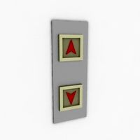
Buttons
...buttons
archibase planet
lift elevator call buttons
elevator call buttons - 3d model for interior 3d visualization.
3ddd
$1
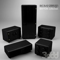
Button
... button , john reeves
набор мебели button от дизайнера john reeves
3d_export
$5
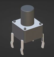
Button
...button
3dexport
smd button<br>verts 2.180<br>faces 3.848
turbosquid
$4

Button
...
turbosquid
royalty free 3d model button for download as fbx on turbosquid: 3d models for games, architecture, videos. (1297941)
turbosquid
$1

Button
...
turbosquid
royalty free 3d model button for download as fbx on turbosquid: 3d models for games, architecture, videos. (1392935)
turbosquid
$9
buttons
...id
royalty free 3d model buttons for download as max and fbx on turbosquid: 3d models for games, architecture, videos. (1404875)
turbosquid
$6

button
...uid
royalty free 3d model button for download as 3dm and max on turbosquid: 3d models for games, architecture, videos. (1669204)
turbosquid
$5

Button
...uid
royalty free 3d model button for download as max and fbx on turbosquid: 3d models for games, architecture, videos. (1710868)
turbosquid
$3

Button
...quid
royalty free 3d model button for download as ma and obj on turbosquid: 3d models for games, architecture, videos. (1510524)
turbosquid
$3
Button
...quid
royalty free 3d model button for download as ma and obj on turbosquid: 3d models for games, architecture, videos. (1509961)
Vertical
3ddd
$1
Vertical curtain
...vertical curtain
3ddd
роллеты
vertical curtain
modern curtain
design_connected
$11
Mr.Tubes Vertical
...mr.tubes vertical
designconnected
tonone mr.tubes vertical computer generated 3d model.
3ddd
free

Vertical gardening
... фитомодуль , фитостена
vertical gardening
2000x1000x165
vizpark
$5

Einstein Vertical
...tical is a set of 3d brick textures for modern buildings, including mulit-textures and 4k tileable textures with material layers.
turbosquid
$5

brazier vertical
... free 3d model brazier vertical for download as sldas and ige on turbosquid: 3d models for games, architecture, videos. (1647570)
turbosquid
$18
Vertical blinds
...ee 3d model vertical blinds for download as max, obj, and fbx on turbosquid: 3d models for games, architecture, videos. (1604868)
3d_export
$40

vertical stirling engine
...vertical stirling engine
3dexport
vertical stirling engine
turbosquid
$6
vertical fence
...d model vertical fence for download as c4d, 3ds, dxf, and obj on turbosquid: 3d models for games, architecture, videos. (1571631)
turbosquid
$50

Vertical Garden
... available on turbo squid, the world's leading provider of digital 3d models for visualization, films, television, and games.
turbosquid
$20

vertical flag
... available on turbo squid, the world's leading provider of digital 3d models for visualization, films, television, and games.
System
archibase_planet
free
System
...m
archibase planet
fire alarm system fire alarm box
security light system - 3d model (*.gsm+*.3ds) for interior 3d visualization.
archibase_planet
free
Spider system
...stem spider glass system
spider system to fix glass stefano galli n050912 - 3d model (*.gsm+*.3ds) for interior 3d visualization.
3ddd
$1

Euforia System
...euforia system
3ddd
euforia
euforia system
3d_export
$50
Roof system Truss system 3D Model
...oof system truss system 3d model
3dexport
roof system truss truss stage
roof system truss system 3d model aleksbel 38970 3dexport
3ddd
$1
DVD System
...dvd system
3ddd
dvd , schneider
dvd system
design_connected
free
Seating system
...seating system
designconnected
free 3d model of seating system
3d_export
$5

solar system
...solar system
3dexport
solar system in c4d, with 8k nasa textures
3ddd
$1
Quanta System
...quanta system
3ddd
медицина
quanta system.
лазерное оборудование для медицинских центров
3d_export
$15
solar system
...nd the other the sun, the earth and the moon, the latter has an animation with camera movement included, the files are in spanish
3d_export
$14

missile system
...missile system
3dexport
Box
archibase_planet
free

Box
...box
archibase planet
box carton cardboard box
box 2 - 3d model (*.3ds) for interior 3d visualization.
archibase_planet
free

Box
...box
archibase planet
carton cardboard box box
box 1 - 3d model (*.3ds) for interior 3d visualization.
3d_export
$6
box
...box
3dexport
box
3d_export
$5
Box
...box
3dexport
box
3d_export
$5
box
...box
3dexport
box
3d_export
$5
box
...box
3dexport
box
archibase_planet
free

Box
...box
archibase planet
box box for paper notebook pencil
box - 3d model (*.gsm+*.3ds) for interior 3d visualization.
archibase_planet
free

Box
...box
archibase planet
box carton cardboard box
box n170111 - 3d model (*.gsm+*.3ds) for interior 3d visualization.
archibase_planet
free

Box
...box
archibase planet
box carton cardboard box
box n050411 - 3d model (*.gsm+*.3ds) for interior 3d visualization.
archibase_planet
free

Boxes
...boxes
archibase planet
boxes box case bin
boxes n281213 - 3d model (*.gsm+*.3ds+*.max) for interior 3d visualization.
Mount
3d_export
free

mounting bracket
...mounting plate is the portion of a hinge that attaches to the wood. mounting plates can be used indoors, cabinetry and furniture.
turbosquid
$2

MOUNTING
... available on turbo squid, the world's leading provider of digital 3d models for visualization, films, television, and games.
turbosquid
free

Mounts
... available on turbo squid, the world's leading provider of digital 3d models for visualization, films, television, and games.
turbosquid
free

Mount Fuji
...fuji
turbosquid
free 3d model mount fuji for download as obj on turbosquid: 3d models for games, architecture, videos. (1579977)
3d_export
$5

Headphone mount LR
...headphone mount lr
3dexport
headphone mount l+r
turbosquid
$39

Mount rainier
...quid
royalty free 3d model mount rainier for download as fbx on turbosquid: 3d models for games, architecture, videos. (1492586)
turbosquid
$5

pipe mounting
...quid
royalty free 3d model pipe mounting for download as obj on turbosquid: 3d models for games, architecture, videos. (1293744)
turbosquid
$3

Mounting Tires
...uid
royalty free 3d model mounting tires for download as fbx on turbosquid: 3d models for games, architecture, videos. (1708511)
3d_export
$5

Magnetic GoPro Mount
...pro mount
3dexport
cool magnetic mount for gopro. allows you to mount the camera on flat metal surfaces and get exclusive shots.
turbosquid
$5

Stone Mount
...ty free 3d model stone mount for download as ma, obj, and fbx on turbosquid: 3d models for games, architecture, videos. (1370306)