Thingiverse
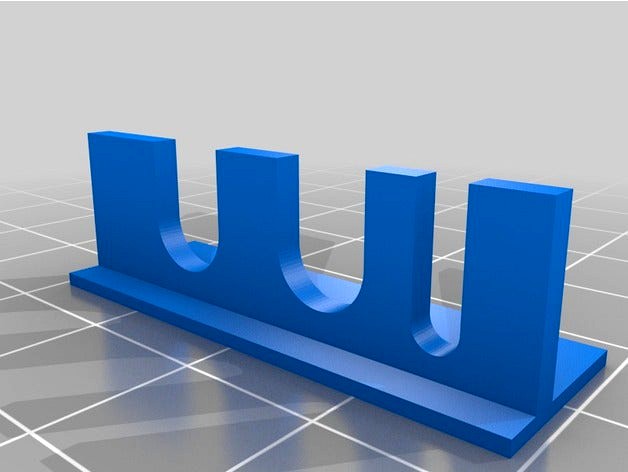
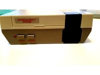
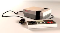
Button and led holder for Mini NES Pi 3 Case by ElTacoLoco
by Thingiverse
Last crawled date: 3 years ago
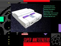
Button and LED holder for Raspberry Pi 3
I made and tried this for the Raspberry Pi 3, but this guide should work with most of the Raspberry PI's but some modells don't have the RUN/Reset pinouts.
The used GPIO pins in this project are the same for Raspberry Pi 3 and Raspberry Pi Zero.
Shutdown - Shuts the Pi down safely from inside the OS.
Reset/Run - Both resets the Pi and will turn it on if it has been shutdown.
LED - lights up whenever the micro usb power cable is connected, the power button
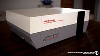
I made this button and led holder for the Mini NES Pi 3 Case By LKM,http://www.thingiverse.com/thing:1887826
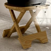
I didn't really spend much time on the button holder, just made it so it should work for me, included the 3D file if anyone feel the need to edit the thing.
The button holder works with all orientations of the Mini NES Pi 3 Case.
What you need:
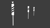
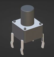
2x Momentary push button.
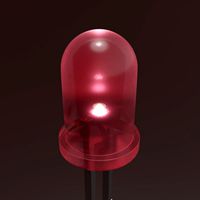
1x 3mm red LED.
1x 150 Ω resistor (higher value is fine if you want a less bright led, but lower value then 68 Ω might break the LED Diode).
Soldering iron & solder wire
6x normal wires or 3x Female To Female jumper wire that you cut in half to get 6x cables with female jumper in one end and a striped wire to solder in the other end.
Heat shrink tubing or electrical tape to insulate the wires.
Superglue
Hot glue gun
2x Male pin header connector or you can solder the cable directly without the pin header connectors.
To get it working i did the following:
1. Reset button:
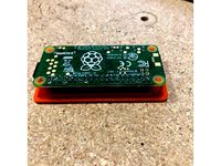
Most Raspberry Pi models have a build in force reboot function, you only need to solder 2 pins to the 2 holes marked "RUN" and the other ends to the Momentary push button. (No programing or further configurations needed)
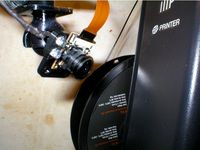
2. LED light:
Simply plugged in 1 female cable to the ground and 1 female cable to the 3.3V pin then solder a 150 Ω resistor to the end of the 3.3V(+) cable and the end of the resistor to the Anode(+) on the LED (the long leg) and soldered the GND(-) cable to the Cathode(-) on the LED (the short leg).
I used a normal 3mm red LED with some hot glue to hold it in place and electrical tape to isolate the metal surface of the legs, but you can also use shrink tube but make shure to isolate each leg separate so you don't short the circuit.
(The 3.3V GPIO PIN are always High (active) when the Raspberry Pi have power connected so the LED will always be active when the Raspberry Pi have power, much like the standby LED on a TV, so you don't need any scripts running in order for it to work with this solution)
3. Off button:
3.1 installing WiringPI:
In order to controll the GPIO input/output on the Raspberry Pi with Retropie I had to install WiringPI.
First check that wiringPi is not already installed. In a terminal, run:
gpio -v
If you get something, then you have it already installed. The next step is to work out if it’s installed via a standard package or from source. If you installed it from source, then you know what you’re doing – carry on – but if it’s installed as a package, you will need to remove the package first. To do this:
sudo apt-get purge wiringpi
hash -r
Then carry on.
If you do not have GIT installed, then under any of the Debian releases (e.g. Raspbian), you can install it with:
sudo apt-get install git-core
If you get any errors here, make sure your Pi is up to date with the latest versions of Raspbian: (this is a good idea to do regularly, anyway)
sudo apt-get update
sudo apt-get upgrade
To obtain WiringPi using GIT:
cd
git clone git://git.drogon.net/wiringPi
If you have already used the clone operation for the first time, then:
cd ~/wiringPi
git pull origin
Will fetch an updated version then you can re-run the build script below.
To build/install there is a new simplified script:
cd ~/wiringPi
./build
The new build script will compile and install it all for you – it does use the sudo command at one point, so you may wish to inspect the script before running it.
Test wiringPi’s installation
run the gpio command to check the installation:
gpio -v
gpio readall
That should give you some confidence that it’s working OK.
Credits for the wiringpi guide where it belongs:
http://wiringpi.com/download-and-install/
WiringPi is released under the GNU Lesser Public License version 3.
3.2 Connecting the power button:
I used this tutorial: https://www.element14.com/community/docs/DOC-78055/l/adding-a-shutdown-button-to-the-raspberry-pi-b
3.3 Programming the power button:
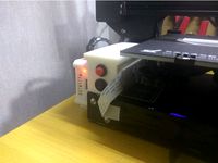
4. Assemble:
I used superglue to get the button/led holder to stick to the case and hotglue to secure the LED in place.
Side note:
I included a breadboard view of how i wired everything.
Be careful I don't take any responsibility if your raspberry pi go up in a puff of smoke or if you hurt yourself or others.
If you are unfamiliar with GPIO/Electronics/Raspberry Pi be careful and read up on it first.
I made and tried this for the Raspberry Pi 3, but this guide should work with most of the Raspberry PI's but some modells don't have the RUN/Reset pinouts.
The used GPIO pins in this project are the same for Raspberry Pi 3 and Raspberry Pi Zero.
Shutdown - Shuts the Pi down safely from inside the OS.
Reset/Run - Both resets the Pi and will turn it on if it has been shutdown.
LED - lights up whenever the micro usb power cable is connected, the power button
I made this button and led holder for the Mini NES Pi 3 Case By LKM,http://www.thingiverse.com/thing:1887826
I didn't really spend much time on the button holder, just made it so it should work for me, included the 3D file if anyone feel the need to edit the thing.
The button holder works with all orientations of the Mini NES Pi 3 Case.
What you need:
2x Momentary push button.
1x 3mm red LED.
1x 150 Ω resistor (higher value is fine if you want a less bright led, but lower value then 68 Ω might break the LED Diode).
Soldering iron & solder wire
6x normal wires or 3x Female To Female jumper wire that you cut in half to get 6x cables with female jumper in one end and a striped wire to solder in the other end.
Heat shrink tubing or electrical tape to insulate the wires.
Superglue
Hot glue gun
2x Male pin header connector or you can solder the cable directly without the pin header connectors.
To get it working i did the following:
1. Reset button:
Most Raspberry Pi models have a build in force reboot function, you only need to solder 2 pins to the 2 holes marked "RUN" and the other ends to the Momentary push button. (No programing or further configurations needed)
2. LED light:
Simply plugged in 1 female cable to the ground and 1 female cable to the 3.3V pin then solder a 150 Ω resistor to the end of the 3.3V(+) cable and the end of the resistor to the Anode(+) on the LED (the long leg) and soldered the GND(-) cable to the Cathode(-) on the LED (the short leg).
I used a normal 3mm red LED with some hot glue to hold it in place and electrical tape to isolate the metal surface of the legs, but you can also use shrink tube but make shure to isolate each leg separate so you don't short the circuit.
(The 3.3V GPIO PIN are always High (active) when the Raspberry Pi have power connected so the LED will always be active when the Raspberry Pi have power, much like the standby LED on a TV, so you don't need any scripts running in order for it to work with this solution)
3. Off button:
3.1 installing WiringPI:
In order to controll the GPIO input/output on the Raspberry Pi with Retropie I had to install WiringPI.
First check that wiringPi is not already installed. In a terminal, run:
gpio -v
If you get something, then you have it already installed. The next step is to work out if it’s installed via a standard package or from source. If you installed it from source, then you know what you’re doing – carry on – but if it’s installed as a package, you will need to remove the package first. To do this:
sudo apt-get purge wiringpi
hash -r
Then carry on.
If you do not have GIT installed, then under any of the Debian releases (e.g. Raspbian), you can install it with:
sudo apt-get install git-core
If you get any errors here, make sure your Pi is up to date with the latest versions of Raspbian: (this is a good idea to do regularly, anyway)
sudo apt-get update
sudo apt-get upgrade
To obtain WiringPi using GIT:
cd
git clone git://git.drogon.net/wiringPi
If you have already used the clone operation for the first time, then:
cd ~/wiringPi
git pull origin
Will fetch an updated version then you can re-run the build script below.
To build/install there is a new simplified script:
cd ~/wiringPi
./build
The new build script will compile and install it all for you – it does use the sudo command at one point, so you may wish to inspect the script before running it.
Test wiringPi’s installation
run the gpio command to check the installation:
gpio -v
gpio readall
That should give you some confidence that it’s working OK.
Credits for the wiringpi guide where it belongs:
http://wiringpi.com/download-and-install/
WiringPi is released under the GNU Lesser Public License version 3.
3.2 Connecting the power button:
I used this tutorial: https://www.element14.com/community/docs/DOC-78055/l/adding-a-shutdown-button-to-the-raspberry-pi-b
3.3 Programming the power button:
4. Assemble:
I used superglue to get the button/led holder to stick to the case and hotglue to secure the LED in place.
Side note:
I included a breadboard view of how i wired everything.
Be careful I don't take any responsibility if your raspberry pi go up in a puff of smoke or if you hurt yourself or others.
If you are unfamiliar with GPIO/Electronics/Raspberry Pi be careful and read up on it first.
Similar models
thingiverse
free
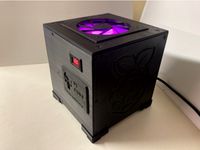
PI CUBE ( octoprint) by madjack911
...r supply 5v 4a (pi4 / temp regulation / fan 40mm / esp8826 / led argb fan 120mm
12v 15a external led power supply
screw m3 and m4
thingiverse
free
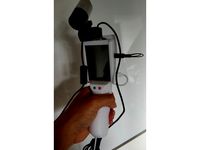
Open CV Handheld Scanner by rolf3d
...t til conf_swapsize=100)
/opencv/build$ sudo /etc/init.d/dphys-swapfile stop
/opencv/build$ sudo /etc/init.d/dphys-swapfile start
thingiverse
free
RKade Mini by DMRadford
...tape to hold the battery leads in place during assembly. the risers in the prints will apply the pressure needed to make contact.
thingiverse
free
Mini SNES Raspberry Pi Zero Case WIP by BitMerge6502
...ion for as inexpensively as possible by using the pi zero as a base computer.
build instructables link coming soon, still a wip.
thingiverse
free

AtarPi by Hassaracker
...tton should now power on and off the pi cleanly to avoid data corruption, not to mention it's a lot easier. more to come ...
thingiverse
free
Raspberry Pi Zero Soldering Holder by PacketPaul
...our pi exactly 8.2 mm above the bottom plate. the pins rest securely in a small box assuring the correct alignment with the pi.
thingiverse
free

Raspberry Pi GPIO Power Blocker for Prusa by Shwalamazula
...spberry-pi-zero-w-preparation-and-installation_2180
power pins are blocked as well. this is for externally-powered raspberry pis.
thingiverse
free
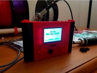
Ender 3 - Box for buttons and cables to the connect leds. by nasp2000
...e box with two dc-dc step down buck. one for 24v to 12v for the leds, and the other 12v to 5v need to raspberry pi.
easy to print
thingiverse
free
![[RPI CUSTOM] Button and led for RPI 3 by jeff38100](/t/8639925.jpg)
[RPI CUSTOM] Button and led for RPI 3 by jeff38100
... just edit the script to power off the led when the rpi is done (and not when it is not powered, as the original script is doing)
thingiverse
free
Raspberry Pi Camera IR LED mount
... to pull the voltage down for the leds. do not try to run 4 leds directly from gpio, use a transistor if you want to switch them.
Eltacoloco
thingiverse
free

M8 to 1/4 inch connector by ElTacoLoco
...o
thingiverse
m8 to 1/4 inch male-male connector.
designed it to connect my 12v bike- and car tire compressor to a air blow gun.
thingiverse
free
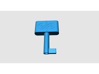
Key to old furniture by ElTacoLoco
...ign diferent size key for other old locks but keeping the handle part, or the other way around designing a new handle to the key.
thingiverse
free

Wall Mount for vacuum cleaner Nilfisk by ElTacoLoco
...ith a bigger hole so you can get a bits holder in to secure a screw against the wall and so you can fit a screw with bigger head.
thingiverse
free
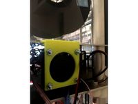
Fan Holder for 40x40x10mm Fan by ElTacoLoco
...iameter instead of 32mm (see v2) to be a better fit but can be harder to print cause of the thin wall so i kept the old 32mm too.
thingiverse
free
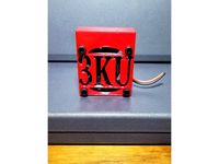
Delta 3KU electronics fan mount by nuroo
...3ku electronics fan mount by nuroo thingiverse remix of eltacoloco#39;s design. just added fan guard in text...
thingiverse
free
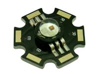
Lens for SMD Power LED (torch distributor/diffuser) snap-fit by ElTacoLoco
...o print with bigger nozzle, updated to v2.
the lens and frame are made to fit for the smd power led model shown in this picture:
thingiverse
free
World of Warcraft Male Undead Warlock Tier 5 by ElTacoLoco
... the file to smal since there are a lot of thin structures and it can be hard to remove the support without breaking of the arms.
thingiverse
free
NES Mini Clone Raspberry Pi Conversion Useful Parts by salona
...and install the necessary script take a look at eltacoloco#39;s excellent thing. https://www.thingiverse.com/thing:2011955 c) a plate that can be...
Nes
turbosquid
$3

NES CONTROLLER
...d
royalty free 3d model nes controller for download as blend on turbosquid: 3d models for games, architecture, videos. (1447807)
3d_export
$5
NES 3D Model
...nes 3d model
3dexport
nin10doh! nintendo nes videogames video-games vidyagamus snes
nes 3d model slottet 100561 3dexport
turbosquid
free
NES Controller
...e 3d model nes controller for download as blend, fbx, and obj on turbosquid: 3d models for games, architecture, videos. (1602782)
turbosquid
$55

Nes Joystick
... 3d model nes joystick for download as c4d, 3ds, fbx, and obj on turbosquid: 3d models for games, architecture, videos. (1569497)
turbosquid
$47
NES mini
...free 3d model nes mini for download as 3ds, max, obj, and fbx on turbosquid: 3d models for games, architecture, videos. (1491229)
turbosquid
$60
Nintendo NES
... available on turbo squid, the world's leading provider of digital 3d models for visualization, films, television, and games.
turbosquid
$7

NES Control
... available on turbo squid, the world's leading provider of digital 3d models for visualization, films, television, and games.
turbosquid
$5
Ne 3
... available on turbo squid, the world's leading provider of digital 3d models for visualization, films, television, and games.
turbosquid
$5

Ne 2
... available on turbo squid, the world's leading provider of digital 3d models for visualization, films, television, and games.
turbosquid
$5

Ne 4
... available on turbo squid, the world's leading provider of digital 3d models for visualization, films, television, and games.
Pi
design_connected
$11

Pi
...pi
designconnected
ligne roset pi chairs computer generated 3d model. designed by thibault desombre.
3d_export
$5

raspberry pi
...raspberry pi
3dexport
carcasa para la raspberry pi
turbosquid
$18
pied
... available on turbo squid, the world's leading provider of digital 3d models for visualization, films, television, and games.
3ddd
$1

Emme pi light
...emme pi light
3ddd
emme pi light
люста emme pi light
3ddd
$1
Emme pi light
...emme pi light
3ddd
emme pi light
бра классическое emme pi light
3ddd
$1

Emme Pi Light
...emme pi light
3ddd
emme pi light
3ddd
$1

Emme Pi Light
...emme pi light
3ddd
emme pi light
design_connected
$16

Pi-Air
...pi-air
designconnected
living divani pi-air lounge chairs computer generated 3d model. designed by harry & camila.
3d_ocean
$15

Manneken Pis
...picting a naked little boy urinating into a fountain’s basin. (wikipedia) the model was sculpted in blender 2.70a rendered wit...
3ddd
$1
Emme pi light
...emme pi light
3ddd
emme pi light
люстра классическая фирма: emme pi light
артикул: 3595/5/cot/12/wh
Button
archibase_planet
free
Buttons
...buttons
archibase planet
lift elevator call buttons
elevator call buttons - 3d model for interior 3d visualization.
3ddd
$1
Button
... button , john reeves
набор мебели button от дизайнера john reeves
3d_export
$5
Button
...button
3dexport
smd button<br>verts 2.180<br>faces 3.848
turbosquid
$4

Button
...
turbosquid
royalty free 3d model button for download as fbx on turbosquid: 3d models for games, architecture, videos. (1297941)
turbosquid
$1

Button
...
turbosquid
royalty free 3d model button for download as fbx on turbosquid: 3d models for games, architecture, videos. (1392935)
turbosquid
$9
buttons
...id
royalty free 3d model buttons for download as max and fbx on turbosquid: 3d models for games, architecture, videos. (1404875)
turbosquid
$6

button
...uid
royalty free 3d model button for download as 3dm and max on turbosquid: 3d models for games, architecture, videos. (1669204)
turbosquid
$5
Button
...uid
royalty free 3d model button for download as max and fbx on turbosquid: 3d models for games, architecture, videos. (1710868)
turbosquid
$3

Button
...quid
royalty free 3d model button for download as ma and obj on turbosquid: 3d models for games, architecture, videos. (1510524)
turbosquid
$3
Button
...quid
royalty free 3d model button for download as ma and obj on turbosquid: 3d models for games, architecture, videos. (1509961)
Mini
turbosquid
$10
Mini Mini Luceplan
...
royalty free 3d model mini mini luceplan for download as max on turbosquid: 3d models for games, architecture, videos. (1227359)
3d_ocean
$39

Mini Cooper
...mini cooper
3docean
cabrioler cooper mini
mini cooper cabrioler
3d_export
$30

Mini lathe
...mini lathe
3dexport
mini lathe
3d_export
$5

mini mouse
...mini mouse
3dexport
mini mouse
3d_export
$5

mini house
...mini house
3dexport
mini house
3d_export
free

Mini Mecha
...mini mecha
3dexport
concept of mini mecha
3d_ocean
$20
Mini Gun
...mini gun
3docean
gatling gun gun machine gun mini gun weapon
model of a mini gatling gun.
3ddd
free
Herve mini
... кофейный , herve
http://www.mobiliavenanti.it/ru/products/hervè-mini
3d_export
$5
mini wall
...mini wall
3dexport
mini wall for living room
3d_export
$5

mini bank
...mini bank
3dexport
mini bank 3d model
Led
3d_export
$5
led
...led
3dexport
the led is cut with all the parts.
3ddd
$1
Monacor / PARL56DMX / LED-320RGBW / LED-345RGBW / LED-300RGB
... прожектор
http://www.monacor.dk/
parl56dmx
led-320rgbw
led-345rgbw
led-300rgb
turbosquid
$10
LED
...led
turbosquid
free 3d model led for download as blend on turbosquid: 3d models for games, architecture, videos. (1691856)
3d_export
$5

led lamp
...led lamp
3dexport
led lamp, brightness animation
3ddd
free
leds-c4
...leds-c4
3ddd
leds-c4
современный торшер
3ddd
free
leds-c4
...leds-c4
3ddd
leds-c4
настольный лампа
turbosquid
$19
LED
... available on turbo squid, the world's leading provider of digital 3d models for visualization, films, television, and games.
turbosquid
$12
Led
... available on turbo squid, the world's leading provider of digital 3d models for visualization, films, television, and games.
turbosquid
free
LED
... available on turbo squid, the world's leading provider of digital 3d models for visualization, films, television, and games.
turbosquid
free

LED
... available on turbo squid, the world's leading provider of digital 3d models for visualization, films, television, and games.
Case
3d_export
$1
case
...case
3dexport
case
archibase_planet
free
Case
...case
archibase planet
showcase show-case glass case
glass-case + cakes - 3d model for interior 3d visualization.
archibase_planet
free
Case
...case
archibase planet
showcase show-case glass case
glass-case for chips - 3d model for interior 3d visualization.
archibase_planet
free
Case
...case
archibase planet
case shelving drawer
case - 3d model for interior 3d visualization.
archibase_planet
free
Case
...case
archibase planet
case rack locker
case - 3d model for interior 3d visualization.
archibase_planet
free
Case
...case
archibase planet
case drawer kitchen furniture
case - 3d model for interior 3d visualization.
archibase_planet
free
Case
...case
archibase planet
case cupboard shelving
glass case - 3d model for interior 3d visualization.
archibase_planet
free
Case
...case
archibase planet
case handbag suitcase
case - 3d model (*.gsm+*.3ds) for interior 3d visualization.
archibase_planet
free

Case
...case
archibase planet
case suitcase
case 5 - 3d model (*.gsm+*.3ds) for interior 3d visualization.
archibase_planet
free
Case
...case
archibase planet
locker case dresser
case - 3d model (*.gsm+*.3ds) for interior 3d visualization.
Holder
archibase_planet
free

Holder
...holder
archibase planet
holder toilet paper holder
holder paper n070712 - 3d model (*.gsm+*.3ds) for interior 3d visualization.
archibase_planet
free

Holder
...e planet
holder rack toilet paper holder
holder toilet roll n240715 - 3d model (*.gsm+*.3ds+*.max) for interior 3d visualization.
archibase_planet
free

Holder
...holder
archibase planet
pen holder support prop
pen holder - 3d model for interior 3d visualization.
archibase_planet
free

Holder
...holder
archibase planet
pole post holder
сhurch cross pole holder - 3d model for interior 3d visualization.
archibase_planet
free
Holder
...holder
archibase planet
holder bathroom ware
shower holder - 3d model (*.gsm+*.3ds) for interior 3d visualization.
archibase_planet
free

Holder
...oilet paper holder
holder paper devon&devon; time black n241113 - 3d model (*.gsm+*.3ds+*.max) for interior 3d visualization.
archibase_planet
free
Holder
...holder
archibase planet
holder hanger hanger for towel
holder 7 - 3d model (*.gsm+*.3ds) for interior 3d visualization.
archibase_planet
free
Holder
...holder
archibase planet
holder hanger hanger for towel
holder 3 - 3d model (*.gsm+*.3ds) for interior 3d visualization.
archibase_planet
free

Holder
...holder
archibase planet
holder towel rack towel-horse
holder - 3d model (*.gsm+*.3ds) for interior 3d visualization.
archibase_planet
free
Holder
...lder
archibase planet
holder hanger hanger for towel
holder towel n250912 - 3d model (*.gsm+*.3ds) for interior 3d visualization.
3
turbosquid
$10
Mountain Bike 3 -3 of 3
...model mountain bike 3 (#3 of 3) for download as fbx and blend on turbosquid: 3d models for games, architecture, videos. (1438752)
turbosquid
$3

Genesis 3 Clothing 3
... available on turbo squid, the world's leading provider of digital 3d models for visualization, films, television, and games.
3d_export
$5
hinge 3
...hinge 3
3dexport
hinge 3
3ddd
$1
Розетка 3
...розетка 3
3ddd
розетка
розетка 3
turbosquid
$50

is-3
... available on turbo squid, the world's leading provider of digital 3d models for visualization, films, television, and games.
turbosquid
$10

Mountain Bike 3 -2 of 3
...model mountain bike 3 (#2 of 3) for download as fbx and blend on turbosquid: 3d models for games, architecture, videos. (1438750)
turbosquid
$10
Mountain Bike 1 -3 of 3
...model mountain bike 1 (#3 of 3) for download as fbx and blend on turbosquid: 3d models for games, architecture, videos. (1438743)
3d_export
$5

3 CATS
...3 cats
3dexport
3 cats pen holder
3ddd
free
3 Буфета
...3 буфета
3ddd
буфет , кантри
3 буфета
turbosquid
$12

Calligraphic Digit 3 Number 3
...hic digit 3 number 3 for download as max, obj, fbx, and blend on turbosquid: 3d models for games, architecture, videos. (1389329)