Thingiverse
Brio - Mechanical (Geared) Interchange/Switch - O1/P1 Track by cgillstrap
by Thingiverse
Last crawled date: 4 years, 9 months ago
Building on a previous design (Brio - Mechanical (Geared) Interchange/Switch - M1 Track)
https://www.thingiverse.com/thing:4793935
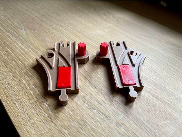
I wanted to see if I could shrink the design into the O1/P1 profile. These turns are really great for tight situations and if you are running battery powered trains you lose a lot of control without the ability to have a switch.
Unfortunately, because of the size, it isn't possible to have the knob in the middle, but I feel the profile of the knob is much less than the stick in some versions (not knocking that approach as that is what Brio does)
I printed these switches with Amolen wood PLA for the track and Prima select red PETG for the functional accessories. The optional sign was printed in grey Prusament PLA.
All the components can be printed in PLA but I have found that the accessories are more durable if printed in PETG
Note about the P1 track: It's not the official Brio dimensions, as creating a female adaptor at the base would otherwise interfere with the switch. I had to extend the track by 17.5mm which means it won't have the same profile as a regular Brio P1 switch. In the end I felt this was a good compromise as the alternative was to only develop the O1 switch.
Assembly Notes
Similar to the M1 instructions, the installation is pretty much self explanatory.
You will need to decide if you want a right or left turn. As the mechanics are under the track, it is not possible to flip this over to reverse directions.
You will want to print one of each of the common accessories and then one of each for the accessories that are paired to the track (RH or LH)
There are a couple of pieces with tight tolerances, to ensure that things do not move once assembled. These are:
Retaining plate: After you insert the 28mm gear, (The big round one) the retaining plate goes over this and slots into the holes on either side. This will be a tight fit by design. I have found success in positioning the peg into the hole and them pushing down firmly on a flat surface on each side to seat. This plate keeps the 28mm cog within the assembly. It should be flush to the bottom once assembled.
20mm Gear and Gear Cap: The gear cap shaft is intentionally .5mm wider than the gear hole. This is to ensure a tight fit with no slippage. One side of the gear is filleted and that is the side that needs to face into the track. That should help push the shaft into the gear. Similar to the retaining plate you may find success if you position the gear and cap and then pushing down the track on a flat surface.
In general I found forcing things too much causes breakages. A tip I found useful was to lubricate parts with liquid soap to help put in place if there was issues. Apologies if you have assembly issues, printing screws or fasteners at these tolerances does not seem like the right answer.
Future Iterations
It may be possible to integrate the Signal Lights (https://www.thingiverse.com/thing:4807078) with this print, but I haven't tried that. The mechanics are the same as in the M1 switch, but I don't think it would look right with where the switch island is.
I do intend to design a much simpler ground level signal as a remix which I will introduce in due course.
As always, interested in comments. I haven't found a mechanical switch of any sort for this pattern so hope people find this useful
https://www.thingiverse.com/thing:4793935
I wanted to see if I could shrink the design into the O1/P1 profile. These turns are really great for tight situations and if you are running battery powered trains you lose a lot of control without the ability to have a switch.
Unfortunately, because of the size, it isn't possible to have the knob in the middle, but I feel the profile of the knob is much less than the stick in some versions (not knocking that approach as that is what Brio does)
I printed these switches with Amolen wood PLA for the track and Prima select red PETG for the functional accessories. The optional sign was printed in grey Prusament PLA.
All the components can be printed in PLA but I have found that the accessories are more durable if printed in PETG
Note about the P1 track: It's not the official Brio dimensions, as creating a female adaptor at the base would otherwise interfere with the switch. I had to extend the track by 17.5mm which means it won't have the same profile as a regular Brio P1 switch. In the end I felt this was a good compromise as the alternative was to only develop the O1 switch.
Assembly Notes
Similar to the M1 instructions, the installation is pretty much self explanatory.
You will need to decide if you want a right or left turn. As the mechanics are under the track, it is not possible to flip this over to reverse directions.
You will want to print one of each of the common accessories and then one of each for the accessories that are paired to the track (RH or LH)
There are a couple of pieces with tight tolerances, to ensure that things do not move once assembled. These are:
Retaining plate: After you insert the 28mm gear, (The big round one) the retaining plate goes over this and slots into the holes on either side. This will be a tight fit by design. I have found success in positioning the peg into the hole and them pushing down firmly on a flat surface on each side to seat. This plate keeps the 28mm cog within the assembly. It should be flush to the bottom once assembled.
20mm Gear and Gear Cap: The gear cap shaft is intentionally .5mm wider than the gear hole. This is to ensure a tight fit with no slippage. One side of the gear is filleted and that is the side that needs to face into the track. That should help push the shaft into the gear. Similar to the retaining plate you may find success if you position the gear and cap and then pushing down the track on a flat surface.
In general I found forcing things too much causes breakages. A tip I found useful was to lubricate parts with liquid soap to help put in place if there was issues. Apologies if you have assembly issues, printing screws or fasteners at these tolerances does not seem like the right answer.
Future Iterations
It may be possible to integrate the Signal Lights (https://www.thingiverse.com/thing:4807078) with this print, but I haven't tried that. The mechanics are the same as in the M1 switch, but I don't think it would look right with where the switch island is.
I do intend to design a much simpler ground level signal as a remix which I will introduce in due course.
As always, interested in comments. I haven't found a mechanical switch of any sort for this pattern so hope people find this useful