Thingiverse
box API for SCAD by Claymore
by Thingiverse
Last crawled date: 3 years ago
Introduction
This thing is just a SCAD script that provide an API to manipulate parts of a models by placing them relative to each other.
When writing SCAD models i found out that the result scripts are not readable. Even when i read them myself many days later i don't understand what i wrote and why i wrote them this way.
The main reason is that i use a lot of constant values computed or measured on parts in real life and even with comments in code this is hard to read. Furthermore when i want to make modifications i don't know where to apply them in code.
This API simplify all my designs by allowing me to place parts relatives to each other.
This thing is designed using this library: http://www.thingiverse.com/thing:2005142
How it works
Boxes basics
Each elementary part of the model (cube, cylinder etc...) can be bounded by a box that you create using the api boxCreate().
Boxes faces are always aligned with x,y,z axis. The boxCreate api just take the size of the box on [x,y,z] before any rotation:
boundingBox = boxCreate ( [1, 1, 1] );
The object returned is an array on which we can get some computed values using indexes (which are all listed at the beginning or the file box.scad).
For instance these indexes returns the size elements of the box. When the box is first created these are just the values we gave:
boundingBox[idx]
boundingBox[idy]
boundingBox[idz]
The following indexes returns the position values on x,y,z of the center of the box. The center of the box is the point that we move using transformations, it can be anywhere in the box. When the box is first created the center is the barycenter of all its points and it is placed at coordinate [0,0,0]:
boundingBox[ix]
boundingBox[iy]
boundingBox[iz]
The following indexes returns the x position of the left face:
boundingBox[ixmin]
boundingBox[ileft]
The equivalences are made such you are the observer that look in the direction of Y axis with Z going top and X going right:
ixmin = ileft
ixmax = iright
iymin = ifront
iymax = iback
izmin = ibottom
izmax = itop
Transformations
The box can be translated, rotated and resized.
The object contains actualy 2 boxes: the outer box that we just saw (global coordinates) and the inner box (local coordinates).
To access to local coordinates, just add an l in indexes :
ilxmin = illeft
ilxmax = ilright
ilymin = ilfront
ilymax = ilback
ilzmin = ilbottom
ilzmax = iltop
When the box is first created the local and global coordinates have the same values. But they will differ when you use transformations:
When you translate the box using boxTranslatexxx or boxMovexxx functions only the global box is translated, the local box stay unmodified,
When you rotate the box using boxRotatexxx functions only the global box is recomputed in order to hold the rotate part of the local box.
When you resize the box using boxResizexxx or boxExtrudexxx functions the local box is resized and the global box is recomputed in order to hold the rotate part of the local box.
Another way to explain this is: The global box is the bounding box of the local box after translation/rotation.
Rendering
The following APIs allow you to get SCAD modules with elementary shapes bounded in a box:
boxRenderCube(bbox): this module builds a SCAD cube bounded in the local box, rotated and translated,
boxRenderCylinderX(bbox): this module builds a SCAD cylinder oriented on the X axis of the local box, rotated and translated,
boxRenderCylinderY(bbox): this module builds a SCAD cylinder oriented on the Y axis of the local box, rotated and translated,
boxRenderCylinderZ(bbox): this module builds a SCAD cylinder oriented on the Z axis of the local box, rotated and translated,
boxRenderConeRight(bbox, sd): this module builds a SCAD cylinder oriented on the X. The small diameter (sd) of the cone is placed on the right face of the local box,
boxRenderConeLeft(bbox, sd): this module builds a SCAD cylinder oriented on the X. The small diameter (sd) of the cone is placed on the left face of the local box,
boxRenderConeBack(bbox, sd): this module builds a SCAD cylinder oriented on the X. The small diameter (sd) of the cone is placed on the back face of the local box,
boxRenderConeFront(bbox, sd): this module builds a SCAD cylinder oriented on the X. The small diameter (sd) of the cone is placed on the front face of the local box,
boxRenderConeTop(bbox, sd): this module builds a SCAD cylinder oriented on the X. The small diameter (sd) of the cone is placed on the top face of the local box,
boxRenderConeBottom(bbox, sd): this module builds a SCAD cylinder oriented on the X. The small diameter (sd) of the cone is placed on the bottom face of the local box.
The cylinders diameters and cone large diameter are computed as the minimum value of the borders of the cylinder's/cone's base.
Note that the resulting object is bounded by the global box.
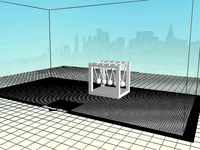
Examples
The images of this thing is the result of the following scripts, as you can see the only scalar values are the initial bounding boxes of the items. These boxes are then moved and rotated with box API transformations and then rendered using box API modules (boxRenderxxx).
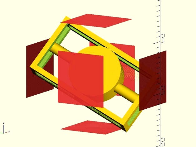
Example 1
In this scene we want the mainBox centered at [0,0,0], the cylinderX sticked to the center of the right face of the mainBox, then the cylinderY is actually a cone based in the center of the cylinderX and rotated by 42°.
include
$fn = 180;
mainBoxSize = [8.4, 9.1, 10.5];
cylinderXSize = [8.5, 1.2, 1.2];
cylinderYSize = [0.8, 5.4, 0.8];
cylinderYRotation = [ 42, 0, 0];
mainBox = boxCreate ( mainBoxSize );
cylinderX = boxMoveLeftTo ( boxCreate ( cylinderXSize ), mainBox[ixmax] );
cylinderY = boxMoveFrontTo (
boxMoveBottomTo (
boxMoveLeftTo (
boxRotate (
boxCreate ( cylinderYSize )
, cylinderYRotation )
, cylinderX[ix] )
, cylinderX[iy] )
, cylinderX[iz]
);
color ( "White" )
boxRenderCube ( mainBox );
color ( "Red" )
boxRenderCylinderX ( cylinderX );
color ( "Green" )
boxRenderConeBack ( cylinderY );
Example 2
This script generates more complex structures with still simple code:
// Test of some modules
test =
boxRotate (
boxMoveTo (
boxRotate (
boxCreate ( [2, 10, 20] )
, [110,30,20]
)
, [10, 20, 30]
)
, [10,0,0]
)
;
testResized = boxResize ( test, 1 );
plane = boxCreate ( [0.0001, 10, 10] );
difference() {
boxRenderCube( testResized );
boxRenderCube( boxResizeX ( test, 1 ) );
boxRenderCube( boxResizeY ( test, 1 ) );
boxRenderCube( boxResizeZ ( test, 1 ) );
}
boxRenderCylinderX ( boxResizeX ( test, 1 ), $fn=100 );
boxRenderCylinderY ( boxResizeY ( test, 1 ), $fn=100 );
boxRenderCylinderZ ( boxResizeZ ( test, 1 ), $fn=100 );
// boxRenderCylinderZ( test );
#translate( [ testResized[ixmax], testResized[iy], testResized[iz] ] )
rotate( [0,0,0] )
boxRenderCube( plane );
#translate( [ testResized[ixmin], testResized[iy], testResized[iz] ] )
rotate( [0,0,0] )
boxRenderCube( plane );
#translate( [ testResized[ix], testResized[iymax], testResized[iz] ] )
rotate( [0,0,90] )
boxRenderCube( plane );
#translate( [ testResized[ix], testResized[iymin], testResized[iz] ] )
rotate( [0,0,90] )
boxRenderCube( plane );
#translate( [ testResized[ix], testResized[iy], testResized[izmax] ] )
rotate( [0,90,0] )
boxRenderCube( plane );
#translate( [ testResized[ix], testResized[iy], testResized[izmin] ] )
rotate( [0,90,0] ) boxRenderCube( plane );
This thing is just a SCAD script that provide an API to manipulate parts of a models by placing them relative to each other.
When writing SCAD models i found out that the result scripts are not readable. Even when i read them myself many days later i don't understand what i wrote and why i wrote them this way.
The main reason is that i use a lot of constant values computed or measured on parts in real life and even with comments in code this is hard to read. Furthermore when i want to make modifications i don't know where to apply them in code.
This API simplify all my designs by allowing me to place parts relatives to each other.
This thing is designed using this library: http://www.thingiverse.com/thing:2005142
How it works
Boxes basics
Each elementary part of the model (cube, cylinder etc...) can be bounded by a box that you create using the api boxCreate().
Boxes faces are always aligned with x,y,z axis. The boxCreate api just take the size of the box on [x,y,z] before any rotation:
boundingBox = boxCreate ( [1, 1, 1] );
The object returned is an array on which we can get some computed values using indexes (which are all listed at the beginning or the file box.scad).
For instance these indexes returns the size elements of the box. When the box is first created these are just the values we gave:
boundingBox[idx]
boundingBox[idy]
boundingBox[idz]
The following indexes returns the position values on x,y,z of the center of the box. The center of the box is the point that we move using transformations, it can be anywhere in the box. When the box is first created the center is the barycenter of all its points and it is placed at coordinate [0,0,0]:
boundingBox[ix]
boundingBox[iy]
boundingBox[iz]
The following indexes returns the x position of the left face:
boundingBox[ixmin]
boundingBox[ileft]
The equivalences are made such you are the observer that look in the direction of Y axis with Z going top and X going right:
ixmin = ileft
ixmax = iright
iymin = ifront
iymax = iback
izmin = ibottom
izmax = itop
Transformations
The box can be translated, rotated and resized.
The object contains actualy 2 boxes: the outer box that we just saw (global coordinates) and the inner box (local coordinates).
To access to local coordinates, just add an l in indexes :
ilxmin = illeft
ilxmax = ilright
ilymin = ilfront
ilymax = ilback
ilzmin = ilbottom
ilzmax = iltop
When the box is first created the local and global coordinates have the same values. But they will differ when you use transformations:
When you translate the box using boxTranslatexxx or boxMovexxx functions only the global box is translated, the local box stay unmodified,
When you rotate the box using boxRotatexxx functions only the global box is recomputed in order to hold the rotate part of the local box.
When you resize the box using boxResizexxx or boxExtrudexxx functions the local box is resized and the global box is recomputed in order to hold the rotate part of the local box.
Another way to explain this is: The global box is the bounding box of the local box after translation/rotation.
Rendering
The following APIs allow you to get SCAD modules with elementary shapes bounded in a box:
boxRenderCube(bbox): this module builds a SCAD cube bounded in the local box, rotated and translated,
boxRenderCylinderX(bbox): this module builds a SCAD cylinder oriented on the X axis of the local box, rotated and translated,
boxRenderCylinderY(bbox): this module builds a SCAD cylinder oriented on the Y axis of the local box, rotated and translated,
boxRenderCylinderZ(bbox): this module builds a SCAD cylinder oriented on the Z axis of the local box, rotated and translated,
boxRenderConeRight(bbox, sd): this module builds a SCAD cylinder oriented on the X. The small diameter (sd) of the cone is placed on the right face of the local box,
boxRenderConeLeft(bbox, sd): this module builds a SCAD cylinder oriented on the X. The small diameter (sd) of the cone is placed on the left face of the local box,
boxRenderConeBack(bbox, sd): this module builds a SCAD cylinder oriented on the X. The small diameter (sd) of the cone is placed on the back face of the local box,
boxRenderConeFront(bbox, sd): this module builds a SCAD cylinder oriented on the X. The small diameter (sd) of the cone is placed on the front face of the local box,
boxRenderConeTop(bbox, sd): this module builds a SCAD cylinder oriented on the X. The small diameter (sd) of the cone is placed on the top face of the local box,
boxRenderConeBottom(bbox, sd): this module builds a SCAD cylinder oriented on the X. The small diameter (sd) of the cone is placed on the bottom face of the local box.
The cylinders diameters and cone large diameter are computed as the minimum value of the borders of the cylinder's/cone's base.
Note that the resulting object is bounded by the global box.
Examples
The images of this thing is the result of the following scripts, as you can see the only scalar values are the initial bounding boxes of the items. These boxes are then moved and rotated with box API transformations and then rendered using box API modules (boxRenderxxx).
Example 1
In this scene we want the mainBox centered at [0,0,0], the cylinderX sticked to the center of the right face of the mainBox, then the cylinderY is actually a cone based in the center of the cylinderX and rotated by 42°.
include
$fn = 180;
mainBoxSize = [8.4, 9.1, 10.5];
cylinderXSize = [8.5, 1.2, 1.2];
cylinderYSize = [0.8, 5.4, 0.8];
cylinderYRotation = [ 42, 0, 0];
mainBox = boxCreate ( mainBoxSize );
cylinderX = boxMoveLeftTo ( boxCreate ( cylinderXSize ), mainBox[ixmax] );
cylinderY = boxMoveFrontTo (
boxMoveBottomTo (
boxMoveLeftTo (
boxRotate (
boxCreate ( cylinderYSize )
, cylinderYRotation )
, cylinderX[ix] )
, cylinderX[iy] )
, cylinderX[iz]
);
color ( "White" )
boxRenderCube ( mainBox );
color ( "Red" )
boxRenderCylinderX ( cylinderX );
color ( "Green" )
boxRenderConeBack ( cylinderY );
Example 2
This script generates more complex structures with still simple code:
// Test of some modules
test =
boxRotate (
boxMoveTo (
boxRotate (
boxCreate ( [2, 10, 20] )
, [110,30,20]
)
, [10, 20, 30]
)
, [10,0,0]
)
;
testResized = boxResize ( test, 1 );
plane = boxCreate ( [0.0001, 10, 10] );
difference() {
boxRenderCube( testResized );
boxRenderCube( boxResizeX ( test, 1 ) );
boxRenderCube( boxResizeY ( test, 1 ) );
boxRenderCube( boxResizeZ ( test, 1 ) );
}
boxRenderCylinderX ( boxResizeX ( test, 1 ), $fn=100 );
boxRenderCylinderY ( boxResizeY ( test, 1 ), $fn=100 );
boxRenderCylinderZ ( boxResizeZ ( test, 1 ), $fn=100 );
// boxRenderCylinderZ( test );
#translate( [ testResized[ixmax], testResized[iy], testResized[iz] ] )
rotate( [0,0,0] )
boxRenderCube( plane );
#translate( [ testResized[ixmin], testResized[iy], testResized[iz] ] )
rotate( [0,0,0] )
boxRenderCube( plane );
#translate( [ testResized[ix], testResized[iymax], testResized[iz] ] )
rotate( [0,0,90] )
boxRenderCube( plane );
#translate( [ testResized[ix], testResized[iymin], testResized[iz] ] )
rotate( [0,0,90] )
boxRenderCube( plane );
#translate( [ testResized[ix], testResized[iy], testResized[izmax] ] )
rotate( [0,90,0] )
boxRenderCube( plane );
#translate( [ testResized[ix], testResized[iy], testResized[izmin] ] )
rotate( [0,90,0] ) boxRenderCube( plane );
Similar models
thingiverse
free
Coner Module by Georgewchilds
...tom and top of cone, diameter of bottom and top of center cone hole.
additional horizontal screw hole is included in scad file.
thingiverse
free
Four in a Line by guberti
...14])cube([3.5,4,88]);
token:
difference(){
cylinder(1.8,4.8,4.8);
cylinder(0.5,4,4);
translate([0,0,1.3])cylinder(0.5,4,4);
}
thingiverse
free
Roundness test by prestige09
...t in your slicer x scale = 1.0024, y scale =1,
depending on the closest value to 200 mm.
thank you for your attention!
<==>
thingiverse
free
Harbor Point Tower Chicago by Idaho_Builder
...2+24],center=true);
translate([-30,160,(4012+24)/2])
color([1,0,1],.5)
rotate([0,0,240])
cube([350,250,4012+24],center=true);
}
}
thingiverse
free
Sphere bracelet by guberti
...,90])cylinder(20,10,10); }
rotate([300,0,0])difference() { translate([10,2,2])sphere(10); rotate([90,90,90])cylinder(20,10,10); }
thingiverse
free
Alesis DM10 Module Mount Arm by BloodlessLove
...,63]) cylinder(162,12.5,12.5,$fn=100);
translate([0,0,227]) #rotate ([90,0,0]) cylinder (h = 26, r=9.8, center = true, $fn=100);}
thingiverse
free
Basketball Hoop by guberti
...
translate([-17,6,37])cube([2,8,8]);
}
translate([-20,10,17])rotate_extrude(convexity = 10)
translate([6, 20, 20])
circle(r = 1);
thingiverse
free
Newton's cradle by guberti
...-40,-10,0])rotate([-30,0,0])cylinder(35,1,1);
translate([0,23,30])translate([-40,-10,0])rotate([90,0,0])cylinder(45,1,1,$fn=100);
thingiverse
free
Holey dice (3D printing test) by guberti
...0,-25,-25]) cylinder(50,15,15); rotate([90,0,0]) cylinder(50,15,15); translate([-3,-25,0])rotate([0,90,0]) cylinder(50,15,15);}
}
thingiverse
free
Dado Box (for use with openscad CSG ops) by merlinjim
...t because i have been reading the tutorials, and they are, in fact, awesome... i decided to tag it with openscadtutorial anyways.
Claymore
turbosquid
$10
Claymore
...bosquid
royalty free 3d model claymore for download as blend on turbosquid: 3d models for games, architecture, videos. (1690137)
turbosquid
$3
Claymore
...urbosquid
royalty free 3d model claymore for download as obj on turbosquid: 3d models for games, architecture, videos. (1385788)
turbosquid
$2
Claymore
...urbosquid
royalty free 3d model claymore for download as max on turbosquid: 3d models for games, architecture, videos. (1232753)
turbosquid
$1
claymore
...bosquid
royalty free 3d model claymore for download as blend on turbosquid: 3d models for games, architecture, videos. (1447119)
turbosquid
$3
Claymore
...
royalty free 3d model claymore for download as blend and obj on turbosquid: 3d models for games, architecture, videos. (1613009)
turbosquid
$18
Claymore
... available on turbo squid, the world's leading provider of digital 3d models for visualization, films, television, and games.
turbosquid
free
claymore
... available on turbo squid, the world's leading provider of digital 3d models for visualization, films, television, and games.
turbosquid
free
Claymore
... available on turbo squid, the world's leading provider of digital 3d models for visualization, films, television, and games.
3d_ocean
$3

Claymore Sword
...scottish shphere steel sword
scottish old medieval claymore steel iron leather brown shphere cylinders game sword blade nice epic
3d_export
$5
claymore skybreaker
...claymore skybreaker
3dexport
Api
turbosquid
$18
Apis
...is
turbosquid
royalty free 3d model apis for download as max on turbosquid: 3d models for games, architecture, videos. (1470014)
3ddd
$1
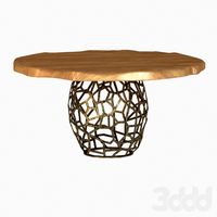
Обеденный стол Brabbu Apis
...обеденный стол brabbu apis
стек не свернут
вес 4500 полигонов
сайтhttp://brabbu.com/en/casegoods/apis-dining-table.php
3d_ocean
$12

Brabbu Apis Table
... and prepared for photo-realistic renderings, close-ups, cg visualization. the table is ready to be inserted in your scene out...
3d_export
free
universal robot aubo i3
...the open system platform supports multiple communication methods、sdk and api and can establish communication with multiple peripheral equipment such...
3d_ocean
$49

Robot Bee
...robot bee 3docean animal animals api bee beetle bugs bumblebee flower flowers fly honey honeybee...
3ddd
$1
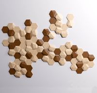
Wooden wall tiles by Monoculo Design Studio
...studio 3ddd плитка spanish firm monoculo design studio’s bee api wood tiles allow you to create any kind of...
thingiverse
free

No API = No SPAM
...the api, and all the spam will go the fuck away!!!!
or at least, secure it! require a key and vet anyone requesting one.
morons!
3d_sky
free

Dining table Brabbu Apis
... table brabbu apis stack not collapsed weight 4500 polygons websitehttp://brabbu.com/en/casegoods/apis-dining-table.php
thingiverse
free
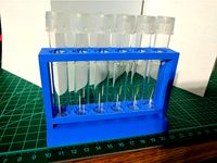
API Test Tube Stand by kern2011
...api test tube stand by kern2011
thingiverse
fits 6 api test tubes.
1-17-17- fixed tolerances for version 2
thingiverse
free

API test tube rack
...ted using 3m command strips or other double sided foam adhesive tapes.
holds 7 api test tubes or test tube of the same diameter.
Scad
3dfindit
free
SCAD
...scad
3dfind.it
catalog: te connectivity
thingiverse
free
THING, SCAD by kaixie
...thing, scad by kaixie
thingiverse
thing, scad
thingiverse
free

questionMark-scad by thingiversedeveloper
...questionmark-scad by thingiversedeveloper
thingiverse
trying out the scad
thingiverse
free
Clothespin scad by carlesoriol
...clothespin scad by carlesoriol
thingiverse
clothespin scad. don't pring the spring!!
thingiverse
free
Mr. SCAD by plangdon
...mr. scad by plangdon
thingiverse
max's first cad design - mr. scad
thingiverse
free

bague scad by TristanJ
...bague scad by tristanj
thingiverse
...
thingiverse
free
coupling scad config by wanick
...coupling scad config by wanick
thingiverse
scad file config sizes
thingiverse
free
made in open scad by BasejCar
...made in open scad by basejcar
thingiverse
made in open scad. use geb.scad
thingiverse
free
Test scad ring by NathanMichaelMoore
...test scad ring by nathanmichaelmoore
thingiverse
test upload of my first scad thing
thingiverse
free

Minimalist SCAD Spheres by nevitdilmen
...minimalist scad spheres by nevitdilmen
thingiverse
minimalist scad spheres
resize before printing
Box
archibase_planet
free
Box
...box
archibase planet
box carton cardboard box
box 2 - 3d model (*.3ds) for interior 3d visualization.
archibase_planet
free
Box
...box
archibase planet
carton cardboard box box
box 1 - 3d model (*.3ds) for interior 3d visualization.
3d_export
$6
box
...box
3dexport
box
3d_export
$5
Box
...box
3dexport
box
3d_export
$5
box
...box
3dexport
box
3d_export
$5
box
...box
3dexport
box
archibase_planet
free
Box
...box
archibase planet
box box for paper notebook pencil
box - 3d model (*.gsm+*.3ds) for interior 3d visualization.
archibase_planet
free
Box
...box
archibase planet
box carton cardboard box
box n170111 - 3d model (*.gsm+*.3ds) for interior 3d visualization.
archibase_planet
free
Box
...box
archibase planet
box carton cardboard box
box n050411 - 3d model (*.gsm+*.3ds) for interior 3d visualization.
archibase_planet
free
Boxes
...boxes
archibase planet
boxes box case bin
boxes n281213 - 3d model (*.gsm+*.3ds+*.max) for interior 3d visualization.