Thingiverse
Bot_Legs_Project (Exoskeleton) by Maddoctor
by Thingiverse
Last crawled date: 4 years, 4 months ago
Assistive Technology.
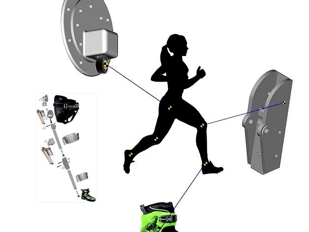
The idea is to make a walking aid for persons who have some motor controls but not enough strength to actually walk. The motors would amplify their intended movement allowing greater mobility.
There's and SWF Video of the motors moving in "thing files" (download) section.
This is an open source project - can you apply your talents to add value? Please do....
Constructive feedback, ideas, designs and insights are welcome.
Just add a comment or a hyperlink.
NB: -- In spite of my username, I'm not a doctor and have no medical training whatsoever! I can't say this work is fit for any purpose other than research.
The STL files are Joints and linkages for 20X20 Bosch Rexroth aluminum extrusion.
Used with GLA750 Linear Actuators (run at 18V DC) and a Mystic 'seat type' kite surfing harness.
I got my 50 mm actuators here: https://gimsonrobotics.co.uk/categories/linear-actuators/products/gla750-12v-dc-small-linear-actuator
I used both plastic (M8 Male) and metal (M6 Male) rod end bearings available from RS Online:http://ie.rs-online.com/web/c/pneumatics-hydraulics-power-transmission/power-transmission-rod-ends-spherical-bearings/rod-ends/?searchTerm=rod+end
and a good many bearings, bushings and bolts "recycled" from an old pair of roller skates.
Leg supports also house switches or other sensors to tell the (optional) Arduino or stand-alone controllers when to drive the motors and when to stop.
There are various control options:
Dual DC Motor drivers - with or without Joystick control / with or without Arduino.
An Arduino and a couple of solid state relay boards (dual H Bridge) to drive the motors at 18V.
Sept 2016 - I got some new controllers to try out. Thus far, the "Cytron 10A 5-25V Dual Channel DC Motor Drivers", purchased from: http://www.robotshop.com/eu/en/10a-5-30v-dual-channel-dc-motor-driver.html
look very promising indeed. (Control option 1)
These controllers come with inbuilt "test" buttons - forward and backwards for each of the 2 motor channels.
The test buttons can be wired directly to the switches on the legs, meaning there's no requirement for Arduino and coding, if simple control fits your needs.
However, they can still be interfaced to Arduino for more advanced control options if That's your requirement.
The Cytron boards also support joystick control - right out of the box!
Two control units will be required (one for each leg) but there is a pleasing simplicity to the (option 1) control layout.
An added benefit is that some protections are built in to the controller board (against short circuits and so on) - so they're pretty robust. So far - I'm very happy with them.
Dual H Bridges (Control option 2)http://mg.elecrow.com/arduino-compatible/shield.htmlhttp://www.homotix.eu/product.php~idx~~~586~~locale~~~225~~Dual+Channel+H_Bridge+Motor+Shield+_8A+22V~.html
Choose your own batteries - I'm using 18v Ni-Cd 'battery drill' batteries (Makita) for the testing - there's probably better choices for endurance, performance, size etc. out there. For function testing - the drill batteries serve the purpose.
The 20X20 aluminium extrusion provides multiple attachment points for linkages, batteries cover panels/enclosures etc. It is strong / lightweight and readily available.
Thigh Support files uploaded. - You may need to print them at 95% scale as the thigh support is right on printer limits for size (200X200X200). If you have a square print bed - place them on the bed at 45 degree angle to maximise the print size.
Note - All Leg supports are best printed at 100% Infill.
I added a general purpose strap attachment point for the harness - for additional supports, back brace etc. Can be attached where needed in your particular situation. For back support -- Straps could be used from the hip motor mount, crossing at the chest and attaching to this clip at the mid point (top) of the back of the harness.
The Arduino code is pretty raw, it's just to get the motors moving. (For control option 2) but it does need more work.
You'll need the excellent driver that was created by Christoph Bober in order to use the .ino file - you'll find it on his site here:http://www.christophbober.com/?p=70
(I just put the .h and the .cpp file in the same directory as the .ino but I believe there are more elegant ways to do it.)
Currently in the duino code - I have only 2 switches are controlling 2 motors. There really needs to be 4 switch inputs. However, It provides a starting point from which to evolve your control solution.
I started writing a build steps manual - I've uploaded a PDF of the build steps document at it's current state of completion. Further updates expected.
An additional stiffener support is needed between the Hip_Harness_Attchmt and the Hip_Motor_Mount. A section of aluminium extrusion to act as a stiffener on the harness will ensure the hip motor movement transfers to the leg rather than causing the harness to crumple.
You can use this project as a starting point, if you choose to implement voice control from a smartphone or inertial referencing - I won't try to stop you :o) -- Just remember to share.
For those who need it, this is a quality of life thing.
I re-used some things I found on Thingiverse - modified them etc. If you deserve credit for any work here please let me know.