Thingiverse
BOR 90 Inspired Trimaran by Tunabarrage
by Thingiverse
Last crawled date: 4 years, 6 months ago
CatchTheWind update
Wingsail parts are done, however due to some complications recently I didn't have a chance to work on the attachment and camber translation mechanisms yet. They will be uploaded later. As it stands, using a short nail glued to the top of the deck that sits in a small hole drilled into the leading edge bottom part, along with properly tensioned rigging going to the rigging mounts on the hulls will allow rotation and let the boat sail.
To assemble the wing, use epoxy or super glue or acetone weld the parts together. The leading edges should be combined first, followed by the trailing edges to the leading edges. attach the bottom part of the wing together using an m3 screw with a washer between the printed parts. Use standard 1.75mm filament as connection for the top two flaps. Once all assembly is complete, use vinyl wrap or shrink wrap or similar to 'skin' the wing.
Inspiration:
The BOR90, or USA 17, as Team Oracle like to call it, was a masterpiece of nautical racing design and materials engineering. Sailed to victory in the 33rd Americas Cup, this fantastic boat brought about a large interest in competitive sailing and design, which affected the recently completed 34th America’s cup, which was raced in foiling 72 foot long rigid winged catamarans.
Goal:
To create a trimaran design inspired by USA 17 that could both be used eventually as an RC or model platform, while also providing ample buoyancy to support a large amount of coins/weight and maintaining a favorable aesthetic. Emphasis is to be placed on ease of 3D printing and minimal support structures.
Theory:
The main hull of the trimaran will provide most of the displacement necessary to support weight, with the outriggers providing stability and ancillary displacement. At model sizes/weights, internal bracing for the hull sections is not necessary and would only serve to increase weight at the cost of buoyancy.
Hull section intersections will be designed with minimal tolerances in order to provide acceptable friction fit assembly of the trimaran, while all other areas of the parts will incorporate a .4mm tolerance to accommodate any printing/printer inaccuracies.
Buoyancy works by creating a pressure differential between water (or any fluid) and another fluid that is separated by a solid object in such a way that the net pressure created by the external fluid acts against the force of gravity and thus causes the object to float. For boats, this works by displacing a given volume of water with the hull of the boat. The density of air is much less than that of water, so the total system of hull+air is less dense than the water that is being displaced with the system, and weighs less for a given volume. To optimize for greater buoyancy, one should design for a hull system that provides the greatest displacement with the lowest weight.
Of course, if the only design consideration was to optimize displacement vs weight, a trimaran is suddenly not very efficient. If I had simply created a massive box with the same relative size as the completed trimaran, it would hold much more weight because it has a much higher displacement. However, my design also intends to create an aesthetically pleasing boat that is based off of an existing design (USA 17), and be usable for RC sailing. Thus, there are many factors that must be considered, including:
Hydrodynamics of the hulls and waterline,
Interaction of the trimaran with waves and common sailing conditions,
Ability to actually sail (eg provide lift with the foils and sail, be steerable etc.)
Structural strength and stiffness so that deformation and flex of the parts do not jeopardize sailing characteristics.
Implementation:
Many of the design decisions that I made were already made or heavily influenced by the design of USA 17, as their R&D team had much higher budgets and experience than I do. Some of the designs borrowed were wave piercing outriggers, crossbeam geometry, and hull layout. These three already satisfy points 1, 2, and 4 from above. However, everything had to be modified to support RC/model scales and speeds, and thus point 3.
In order to provide enough displacement at this size, all 3 of the hulls were increased in width relative to their length, which on a full scale trimaran would introduce too much drag. In this scale, however, the extra buoyancy takes precedence. Similarly, at the speeds of the full scale tri, smaller control surfaces are needed to allow for effective control. At low speeds, however, larger control surfaces relative to boat size are needed. The rudder, and both foils were increased in size. Additionally, the two foils are asymmetrical in order to provide greater lift when sailing.
3D-printability is conserved through limited use of overhangs, and generally simple single walled hull sections without cross-bracing. All hull sections can be friction-fit together.
Testing:
After printing and fitting all of the parts together, I’m happy to say that it floats! Not only does it float, but it supports quite a lot of coins, to boot. However, there are some changes that could have helped the design both structurally, as well as with ease of printing and assembly and it’s ability to sail.
The large middle hull section of the main hull was too weak without any crossbracing or internal supports. I cracked the hull while removing printing supports, and after epoxying the piece back together and joining it with the rear part of the main hull, found that the fit was not snug enough to provide a waterproof seal. This can be remedied by increasing wall thickness from 2mm to 3mm, or, more preferably, adding internal hull crossbracing and struts. This change will be added in version 2.
The outriggers actually provide enough buoyancy to support the entire weight of the craft on their own, but I placed too much focus on buoyancy in the front of the outriggers to combat nosediving while sailing. If the boat ever does fly both of the other hulls, it will probably flip backwards because the center of buoyant force in the outriggers is too far forward of the center of mass/gravity.
In version 2, I will increase the outriggers depth and width in the last 1/3rd of their length, in order to move the center of buoyant force back. It is important to note that this will only be an issue if it is both windy enough to cause the trimaran to fly both of its other hulls, and when travelling upwind.
Printing the hull sections vertically is, I’ve found, the best orientation to reduce printing supports and increase surface quality of the hulls. However, some of the parts made this difficult, such as the rear part of the main hull. Because of the rudder supports located on the end of this part, printing it vertically required heavy supports and greatly decreased the quality on the rear of the hull.
In version 2, I will be separating the rudder mount from the rear of the hull so that the rear hull can be printed vertically with the flat end flat on the bed. The separated rudder mount will also allow for servo and control design flexibility in the future, as well as easy replacement if necessary.
Conclusion:
Though there were some flaws that need to be addressed in my design for version 2, the first version is still functional and good looking. It appears similar to its inspiration, USA 17, and still supports weight in the form of coins. It was relatively easy to 3D print, and also shows that large models can be made with a relatively small 3D printer as long as it is designed for. Assembly could have been easier, but ultimately required relatively little finishing work (Note: I have sanded and epoxied all of the joints because I personally wanted a better looking final product, but this is not necessary in order to have a functional trimaran).
All in all, this has been an incredibly fun project from start to finish. I enjoyed the challenge of designing both a beautiful and simultaneously functional boat. It allowed me to seriously explore surface modelling in solidworks, and has increased my mastery of 3D Modelling more than any other project I’ve completed. In the future, I will be using this model to learn and perfect the mould making functionality in solidworks, and hopefully create a fiberglass version of this trimaran.
Build log and initial thoughts/descriptions:
This is a semi-scaled trimaran inspired by the BOR90/USA 17 Trimaran sailed to victory in the 2010 America's Cup. With a total length of 500mm, a width of nearly 450mm, and a total displacement volume of 559527 Cubic mm, this model is broken down into parts that will fit in a 20cmx20cm build plate printer.
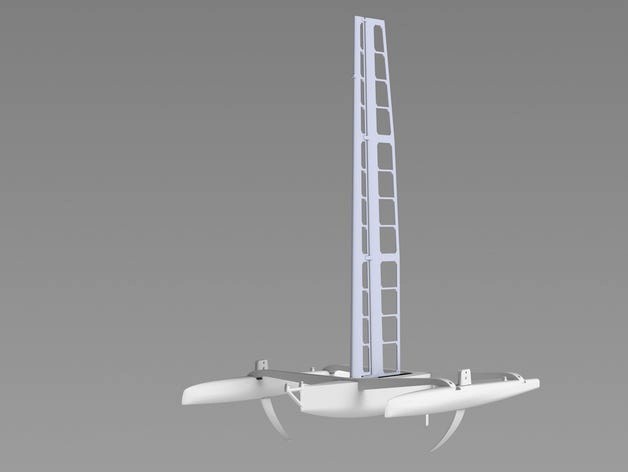
7/15 - About halfway done with the wing, decided to throw up a render of it on the hull.
7/14 - Finished printing all the parts! Everything fits together and looks good, total print time was something like 60 hours (jeez..); it's REALLY big. I'm about halfway done designing the wing for the #CatchTheWind Challenge, it's 150mm long by 600mm high by about 20mm wide. It's using a NACA0015 for the front element and NACA0006 for the rear element, and will be broken down into about 12 parts for printing. I will be epoxying/painting/waterproofing the hull in the coming days and will shoot a video and take more pictures of it floating/holding coins.
Use epoxy or strong glue to join the hull parts together, and then M3 screws to attach the hulls to the crossbeams.
I am also working on a functional rigid wingsail for this model which will be 600mm tall, but for the purposes of the #MakeItFloat challenge, this part shouldn't be included as it will add a substantial amount of weight.
About the model:
Designed using Solidworks 2014
Mass and buoyancy simulations were used to match center of mass with center of Buoyant Force, which will be aligned along z direction with center of mass of the wingsail when it is completed.
The outriggers have a larger buoyant force applied towards the bows, so that when travelling in waves, the trimaran is less likely to pitch pole.
A daggerboard/keel will be added after completion of the wingsail so that the force balancing to provide forward motion when sailing is correct (for the #CatchTheWind Challenge).
Required parts:
2x CrossBeam_Left
2x CrossBeam_right
2x Outrigger Front
2x Outrigger Rear
1x Hull Front
1x Hull Middle
1x Hull rear
1x Outrigger Middle Port
1x Outrigger Middle Starboard
1x Foil port
1x Foil Starboard
1x Rudder
4x M3x30mm screws
4x M3x20mm screws
1x M3x25mm Screw
6x M3 Locknut
1x M3 Washer
1x M3 nut
Wingsail parts are done, however due to some complications recently I didn't have a chance to work on the attachment and camber translation mechanisms yet. They will be uploaded later. As it stands, using a short nail glued to the top of the deck that sits in a small hole drilled into the leading edge bottom part, along with properly tensioned rigging going to the rigging mounts on the hulls will allow rotation and let the boat sail.
To assemble the wing, use epoxy or super glue or acetone weld the parts together. The leading edges should be combined first, followed by the trailing edges to the leading edges. attach the bottom part of the wing together using an m3 screw with a washer between the printed parts. Use standard 1.75mm filament as connection for the top two flaps. Once all assembly is complete, use vinyl wrap or shrink wrap or similar to 'skin' the wing.
Inspiration:
The BOR90, or USA 17, as Team Oracle like to call it, was a masterpiece of nautical racing design and materials engineering. Sailed to victory in the 33rd Americas Cup, this fantastic boat brought about a large interest in competitive sailing and design, which affected the recently completed 34th America’s cup, which was raced in foiling 72 foot long rigid winged catamarans.
Goal:
To create a trimaran design inspired by USA 17 that could both be used eventually as an RC or model platform, while also providing ample buoyancy to support a large amount of coins/weight and maintaining a favorable aesthetic. Emphasis is to be placed on ease of 3D printing and minimal support structures.
Theory:
The main hull of the trimaran will provide most of the displacement necessary to support weight, with the outriggers providing stability and ancillary displacement. At model sizes/weights, internal bracing for the hull sections is not necessary and would only serve to increase weight at the cost of buoyancy.
Hull section intersections will be designed with minimal tolerances in order to provide acceptable friction fit assembly of the trimaran, while all other areas of the parts will incorporate a .4mm tolerance to accommodate any printing/printer inaccuracies.
Buoyancy works by creating a pressure differential between water (or any fluid) and another fluid that is separated by a solid object in such a way that the net pressure created by the external fluid acts against the force of gravity and thus causes the object to float. For boats, this works by displacing a given volume of water with the hull of the boat. The density of air is much less than that of water, so the total system of hull+air is less dense than the water that is being displaced with the system, and weighs less for a given volume. To optimize for greater buoyancy, one should design for a hull system that provides the greatest displacement with the lowest weight.
Of course, if the only design consideration was to optimize displacement vs weight, a trimaran is suddenly not very efficient. If I had simply created a massive box with the same relative size as the completed trimaran, it would hold much more weight because it has a much higher displacement. However, my design also intends to create an aesthetically pleasing boat that is based off of an existing design (USA 17), and be usable for RC sailing. Thus, there are many factors that must be considered, including:
Hydrodynamics of the hulls and waterline,
Interaction of the trimaran with waves and common sailing conditions,
Ability to actually sail (eg provide lift with the foils and sail, be steerable etc.)
Structural strength and stiffness so that deformation and flex of the parts do not jeopardize sailing characteristics.
Implementation:
Many of the design decisions that I made were already made or heavily influenced by the design of USA 17, as their R&D team had much higher budgets and experience than I do. Some of the designs borrowed were wave piercing outriggers, crossbeam geometry, and hull layout. These three already satisfy points 1, 2, and 4 from above. However, everything had to be modified to support RC/model scales and speeds, and thus point 3.
In order to provide enough displacement at this size, all 3 of the hulls were increased in width relative to their length, which on a full scale trimaran would introduce too much drag. In this scale, however, the extra buoyancy takes precedence. Similarly, at the speeds of the full scale tri, smaller control surfaces are needed to allow for effective control. At low speeds, however, larger control surfaces relative to boat size are needed. The rudder, and both foils were increased in size. Additionally, the two foils are asymmetrical in order to provide greater lift when sailing.
3D-printability is conserved through limited use of overhangs, and generally simple single walled hull sections without cross-bracing. All hull sections can be friction-fit together.
Testing:
After printing and fitting all of the parts together, I’m happy to say that it floats! Not only does it float, but it supports quite a lot of coins, to boot. However, there are some changes that could have helped the design both structurally, as well as with ease of printing and assembly and it’s ability to sail.
The large middle hull section of the main hull was too weak without any crossbracing or internal supports. I cracked the hull while removing printing supports, and after epoxying the piece back together and joining it with the rear part of the main hull, found that the fit was not snug enough to provide a waterproof seal. This can be remedied by increasing wall thickness from 2mm to 3mm, or, more preferably, adding internal hull crossbracing and struts. This change will be added in version 2.
The outriggers actually provide enough buoyancy to support the entire weight of the craft on their own, but I placed too much focus on buoyancy in the front of the outriggers to combat nosediving while sailing. If the boat ever does fly both of the other hulls, it will probably flip backwards because the center of buoyant force in the outriggers is too far forward of the center of mass/gravity.
In version 2, I will increase the outriggers depth and width in the last 1/3rd of their length, in order to move the center of buoyant force back. It is important to note that this will only be an issue if it is both windy enough to cause the trimaran to fly both of its other hulls, and when travelling upwind.
Printing the hull sections vertically is, I’ve found, the best orientation to reduce printing supports and increase surface quality of the hulls. However, some of the parts made this difficult, such as the rear part of the main hull. Because of the rudder supports located on the end of this part, printing it vertically required heavy supports and greatly decreased the quality on the rear of the hull.
In version 2, I will be separating the rudder mount from the rear of the hull so that the rear hull can be printed vertically with the flat end flat on the bed. The separated rudder mount will also allow for servo and control design flexibility in the future, as well as easy replacement if necessary.
Conclusion:
Though there were some flaws that need to be addressed in my design for version 2, the first version is still functional and good looking. It appears similar to its inspiration, USA 17, and still supports weight in the form of coins. It was relatively easy to 3D print, and also shows that large models can be made with a relatively small 3D printer as long as it is designed for. Assembly could have been easier, but ultimately required relatively little finishing work (Note: I have sanded and epoxied all of the joints because I personally wanted a better looking final product, but this is not necessary in order to have a functional trimaran).
All in all, this has been an incredibly fun project from start to finish. I enjoyed the challenge of designing both a beautiful and simultaneously functional boat. It allowed me to seriously explore surface modelling in solidworks, and has increased my mastery of 3D Modelling more than any other project I’ve completed. In the future, I will be using this model to learn and perfect the mould making functionality in solidworks, and hopefully create a fiberglass version of this trimaran.
Build log and initial thoughts/descriptions:
This is a semi-scaled trimaran inspired by the BOR90/USA 17 Trimaran sailed to victory in the 2010 America's Cup. With a total length of 500mm, a width of nearly 450mm, and a total displacement volume of 559527 Cubic mm, this model is broken down into parts that will fit in a 20cmx20cm build plate printer.
7/15 - About halfway done with the wing, decided to throw up a render of it on the hull.
7/14 - Finished printing all the parts! Everything fits together and looks good, total print time was something like 60 hours (jeez..); it's REALLY big. I'm about halfway done designing the wing for the #CatchTheWind Challenge, it's 150mm long by 600mm high by about 20mm wide. It's using a NACA0015 for the front element and NACA0006 for the rear element, and will be broken down into about 12 parts for printing. I will be epoxying/painting/waterproofing the hull in the coming days and will shoot a video and take more pictures of it floating/holding coins.
Use epoxy or strong glue to join the hull parts together, and then M3 screws to attach the hulls to the crossbeams.
I am also working on a functional rigid wingsail for this model which will be 600mm tall, but for the purposes of the #MakeItFloat challenge, this part shouldn't be included as it will add a substantial amount of weight.
About the model:
Designed using Solidworks 2014
Mass and buoyancy simulations were used to match center of mass with center of Buoyant Force, which will be aligned along z direction with center of mass of the wingsail when it is completed.
The outriggers have a larger buoyant force applied towards the bows, so that when travelling in waves, the trimaran is less likely to pitch pole.
A daggerboard/keel will be added after completion of the wingsail so that the force balancing to provide forward motion when sailing is correct (for the #CatchTheWind Challenge).
Required parts:
2x CrossBeam_Left
2x CrossBeam_right
2x Outrigger Front
2x Outrigger Rear
1x Hull Front
1x Hull Middle
1x Hull rear
1x Outrigger Middle Port
1x Outrigger Middle Starboard
1x Foil port
1x Foil Starboard
1x Rudder
4x M3x30mm screws
4x M3x20mm screws
1x M3x25mm Screw
6x M3 Locknut
1x M3 Washer
1x M3 nut