Thingiverse
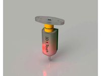
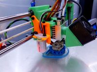
BLTouch / 3DTouch Alternative Z-Probe by svogel7808
by Thingiverse
Last crawled date: 2 years, 11 months ago
This is a remix of the Solenoid Probe by willfly : thing:4390007
A Big thanks to willfly.
I have been thinking of ways to make my own bed level sensor with bin parts that is similar to the BLTouch and Touch-MI probes, but with simplicity in mind.
I got the details to make the coil and plunger from willfly’s design.
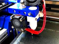
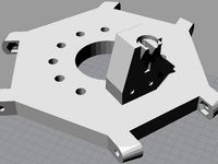
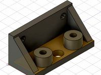
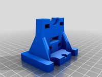
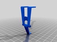
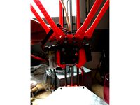
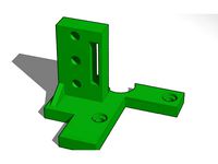
The dimensions are similar to a BLTouch, and thus the same mounts could possibly be used.
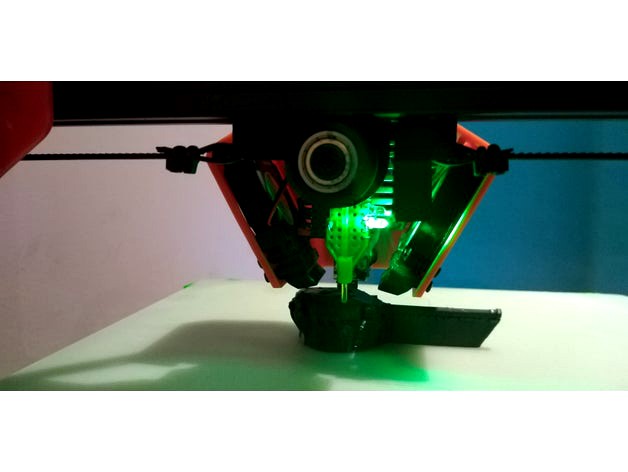
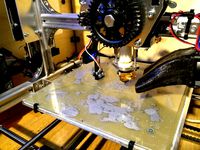
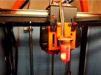
The bed levelling process is similar to that of a BLTouch, but this is a dumb sensor without any alarm triggers and auto testing features, similar to the Touch-Mi probe.
This can be used as a Tuch-Mi probe with the manual deploy option enabled. Stowing will be done by moving the Z-probe close enough to the bed till the magnet pulls the probe towards the set screw.
Assembly:
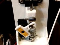
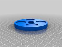
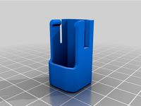
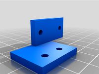
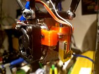
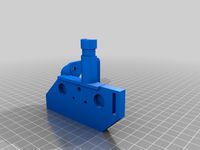
Print the Solenoid_Spool and Body.
Superglue the Spool and Body Together.
I just glued the veroboard and connector in place as well.
Solenoid and Servo Controller:
Extract from willfly :
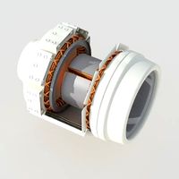
“The coil is wound from 0.14mm enamelled copper wire, length approx. 24 m. The coil resistance is 25 ohm, leading to a current draw of 200 mA for 100 ms when the coil is operating.
The wound coil length is 10 mm. An M3 screw at the top grabs the stowed plunger. It has to be adjusted so that it is not actually touching the plunger, or else probe won't deploy -
the electromagnet has less repulsive force compared to the magnetic attraction of the 5mm rare earth magnet used.”
The current draw of approx. 200ma at 5 volt. I obtained the copper wire from a 80mm 5v fan I had in the parts bin. I unwound the stator coils giving me two lengths of coil that I soldered and insulated to create a continuous wire length.
The solenoid is controlled via a modified 9g servo motor controller.
Remove the board from the servo, unsolder the motor and POT.
Solder two 2k2 resistors to the board in place of the POT to create a 1:1 voltage divider.
The board is then connected to the printer main board to a servo connector.
The servo controller can manage up to 700ma.
I installed the controller in my printer's main board and PSU enclosure.
Probe:
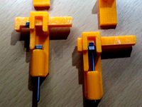
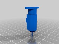
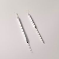
The probe is from the shaft of a faulty 30mm cooling fan from the hot end of my 3d Printer, superglued to a 5mmx2mm neodymium magnet. Alternatively use a 2mm ferrous metal wire cut to about a 10mm length.
The other end is similar, but I glued a length of PETG filament instead of wire to keep weight down.
Sensor:
The sensor is made from the hall effect sensor from the 5V fan. This had 4 pins with two as outputs, and two for power. A 3 pin Hall sensor should also work.
The 4 pin sensor allowed me to connect two LED’s. One for stowed (Safe/Triggered - Green) and one for deployed (Pin Dropped – Red)
A 2n222 - NPN transistor's base is connected to the the hall sensors output, the Collector to Z_Min enstop signal and Emitter is connected to the printer’s Z-MIN end stop Gnd.
I assembled the hall sensor and LED's on a piece of vero board and glued it in place.
Configuration:
Please note - This is not a tutorial on configuring z-probes.
You will need to reconfigure Marlin and flash your Printer.
Please do your own research as I will not take responsibility for any damages to self or property, or your sanity.
The Servo-Hall probe is configured as a servo probe in Marlin.
Marlin v2.0.7.2 has a new wizard to simplify the configuration the Z-Probe offset making setup much easier.
A Side note:
I first tried to use the coil without a servo controller to simplify the design. A single 2n222 or similar transistor can drive the coil to deploy the probe, stowing will be done the same way as the Touch-Mi probe by lowering the Z-Axis until
the probe is stowed by magnetic pull.
An output on the main board could drive the base of the transistor to do this. However, I struggled to configure Marlin for my board (MKS SGEN L V1.0).
I still want to configure/edit Marlin to employ a self test and some fail safes for dumb probes as this.
Please do not hesitate to assist and provide your comments for improvements and point out any mistakes.
Please keep in mind that the idea is to keep the design simple and cheap.
Thanks
A Big thanks to willfly.
I have been thinking of ways to make my own bed level sensor with bin parts that is similar to the BLTouch and Touch-MI probes, but with simplicity in mind.
I got the details to make the coil and plunger from willfly’s design.
The dimensions are similar to a BLTouch, and thus the same mounts could possibly be used.
The bed levelling process is similar to that of a BLTouch, but this is a dumb sensor without any alarm triggers and auto testing features, similar to the Touch-Mi probe.
This can be used as a Tuch-Mi probe with the manual deploy option enabled. Stowing will be done by moving the Z-probe close enough to the bed till the magnet pulls the probe towards the set screw.
Assembly:
Print the Solenoid_Spool and Body.
Superglue the Spool and Body Together.
I just glued the veroboard and connector in place as well.
Solenoid and Servo Controller:
Extract from willfly :
“The coil is wound from 0.14mm enamelled copper wire, length approx. 24 m. The coil resistance is 25 ohm, leading to a current draw of 200 mA for 100 ms when the coil is operating.
The wound coil length is 10 mm. An M3 screw at the top grabs the stowed plunger. It has to be adjusted so that it is not actually touching the plunger, or else probe won't deploy -
the electromagnet has less repulsive force compared to the magnetic attraction of the 5mm rare earth magnet used.”
The current draw of approx. 200ma at 5 volt. I obtained the copper wire from a 80mm 5v fan I had in the parts bin. I unwound the stator coils giving me two lengths of coil that I soldered and insulated to create a continuous wire length.
The solenoid is controlled via a modified 9g servo motor controller.
Remove the board from the servo, unsolder the motor and POT.
Solder two 2k2 resistors to the board in place of the POT to create a 1:1 voltage divider.
The board is then connected to the printer main board to a servo connector.
The servo controller can manage up to 700ma.
I installed the controller in my printer's main board and PSU enclosure.
Probe:
The probe is from the shaft of a faulty 30mm cooling fan from the hot end of my 3d Printer, superglued to a 5mmx2mm neodymium magnet. Alternatively use a 2mm ferrous metal wire cut to about a 10mm length.
The other end is similar, but I glued a length of PETG filament instead of wire to keep weight down.
Sensor:
The sensor is made from the hall effect sensor from the 5V fan. This had 4 pins with two as outputs, and two for power. A 3 pin Hall sensor should also work.
The 4 pin sensor allowed me to connect two LED’s. One for stowed (Safe/Triggered - Green) and one for deployed (Pin Dropped – Red)
A 2n222 - NPN transistor's base is connected to the the hall sensors output, the Collector to Z_Min enstop signal and Emitter is connected to the printer’s Z-MIN end stop Gnd.
I assembled the hall sensor and LED's on a piece of vero board and glued it in place.
Configuration:
Please note - This is not a tutorial on configuring z-probes.
You will need to reconfigure Marlin and flash your Printer.
Please do your own research as I will not take responsibility for any damages to self or property, or your sanity.
The Servo-Hall probe is configured as a servo probe in Marlin.
Marlin v2.0.7.2 has a new wizard to simplify the configuration the Z-Probe offset making setup much easier.
A Side note:
I first tried to use the coil without a servo controller to simplify the design. A single 2n222 or similar transistor can drive the coil to deploy the probe, stowing will be done the same way as the Touch-Mi probe by lowering the Z-Axis until
the probe is stowed by magnetic pull.
An output on the main board could drive the base of the transistor to do this. However, I struggled to configure Marlin for my board (MKS SGEN L V1.0).
I still want to configure/edit Marlin to employ a self test and some fail safes for dumb probes as this.
Please do not hesitate to assist and provide your comments for improvements and point out any mistakes.
Please keep in mind that the idea is to keep the design simple and cheap.
Thanks
Similar models
thingiverse
free

BigBox Dual Hybrid mounting bracket for BLTOUCH z probe by w1ebr
... bltouch dupont connector wiring. one additional wire is needed to hook up the servo mechanism in the bltouch to the rumba board.
thingiverse
free
SteelNeedleProbe by FrankenKai
...rint head,
ususal due to the glitches in the servo control pwm and the servo itself the standard servo probe is not that acurate.
grabcad
free

Holder for calibrations of the hall probe
...be
grabcad
hall probe holder for calibrations of the hall probe between concentrator in helmholtz coil magnetic field apparatus.
grabcad
free

CR Touch
...grabcad
cr touch:
metal probe
optical switch
independent solenoid
bl touch:
plastic probe
hall effect sensor
embedded solenoid
grabcad
free

MICRO SOLENOID
...er. when an electric current is run through the coil, it can create a consistent magnetic field inside a defined region of space.
thingiverse
free
CrashProbe (Z auto leveling by Crash) by Dexerit
...8 x0 y0 ;home x and y only
g29 ;3 point bed probe
g1 z.5 f200 ;force probe retraction
source: http://reprap.org/wiki/crashprobe
thingiverse
free
SCTouch DIY BLTouch Z Probe by chanders
...ere is interest i’ll update with a non-manual solution.
https://www.facebook.com/shivanand.chanderbally/videos/10155084090041863/
thingiverse
free
Brushless Motor using CPU FAN hall sensor circuit by Manders36
... brushless fan by harvesting the hall sensor and controller from a 12v cpu fan, hand wound coils, and 4 strong neodymium magnets.
thingiverse
free
Wolfstock effect with Z probe by cpdude
...with a built-in z probe mount.
oh...and it uses a 8mm wide magnet to hold the probe in the up position. i deploy it manually.
thingiverse
free
K8200/3Drag Z-probe for Marlin Auto bed leveling by magu
... chisel shaped, not fitting in the original design.
my fork of marlin with k8200 specific configuration can be found on github.
3Dtouch
thingiverse
free
3DTouch Holder by sopak
...3dtouch holder by sopak
thingiverse
universal 3dtouch and bltouch mount holes are 3mm with 5mm distance.
thingiverse
free
3DTouch binder by zull
...3dtouch binder by zull
thingiverse
platform for 3dtouch sensor from geeetech for geeetech i3 pro b with mk8 extruder
thingiverse
free
3DTouch Shield (Cover) by mardun
...e
shield/cover for 3dtouch to minimize led light. i tried to use other (mainly for bltouch) but they will not fit to my 3dtouch.
thingiverse
free
3DTouch model (STEP) by Leoliss
...retract - move needle in 3.8mm up. and yes, this is 3dtouch. bltouch have slightly different dimensions.
stl is just for preview.
thingiverse
free
GEEETech E3D v6 with 3DTouch by Minims
...geeetech e3d v6 with 3dtouch by minims
thingiverse
e3d v6 with 3dtouch for metal carriage
thingiverse
free
3dTouch probe model by deadcat
...e model by deadcat
thingiverse
this a fusion360 model of the 3dtouch to use when designing mounts. i have also included the stl.
thingiverse
free
3DTouch lock by markost
...he pin while printing and started breaking my prints and due potential damage to the sensor itself, i designed a pin lock for it.
thingiverse
free

BIQU B1 3DTouch mount by iNardex
...s not good for 3dtouch sensor.
designed for and tested with a 3dtouch v3.0.
i added the fusion360 project for any customizations.
thingiverse
free

Suport 3Dtouch BLTouch Graber Tec3d
...suport 3dtouch bltouch graber tec3d
thingiverse
suporte para fixar 3dtouch ou bltouch na extrusora graber i3 da tec3d.
thingiverse
free
3DTouch\BLTouch Holder for MiniTree T3 by zekeda1
...3dtouch\bltouch holder for minitree t3 by zekeda1
thingiverse
simple holder of 3dtouch\bltouch for minitree t3 3d printer.
Bltouch
thingiverse
free
Support bltouch by TonyJ
...support bltouch by tonyj
thingiverse
support bltouch
thingiverse
free
BLTOUCH for MICRON3DP by lamerhouse
...bltouch for micron3dp by lamerhouse
thingiverse
bltouch for micron3dp
thingiverse
free
SapphirePro mount for Bltouch
...sapphirepro mount for bltouch
thingiverse
sapphirepro mount for bltouch
thingiverse
free
ender6 BLtouch by chimaer
...ender6 bltouch by chimaer
thingiverse
ender6 bltouch
this is an external bracket
thingiverse
free
BLTouch KP3s by 1devilman1
...bltouch kp3s by 1devilman1
thingiverse
bltouch mount for kingroon kp3s
thingiverse
free
Bltouch support adjustable
...bltouch support adjustable
thingiverse
adjustable support for bltouch, p3steel.
thingiverse
free
BMG NEREUS BLTOUCH
...bmg nereus bltouch
thingiverse
petg
m3 screws and nuts for the bltouch
thingiverse
free

BLTouch Bracket by tidh666
...bltouch bracket by tidh666
thingiverse
serves to attach the bltouch sensor to the extruders
thingiverse
free
bltouch mount by wars
...bltouch mount by wars
thingiverse
reinforced bracket for bltouch cooperates with high_clearance_cr10_oem_fang_mod
thingiverse
free

BLTouch Holder by Jonthan06
...bltouch holder by jonthan06
thingiverse
support bltouch pour wanhao d12
Probe
turbosquid
$25
Probe
... available on turbo squid, the world's leading provider of digital 3d models for visualization, films, television, and games.
turbosquid
$12
Mars probe space space exploration lunar probe
...be space space exploration lunar probe for download as max on turbosquid: 3d models for games, architecture, videos. (1630876)
turbosquid
$35
Space Probe
...osquid
royalty free 3d model space probe for download as c4d on turbosquid: 3d models for games, architecture, videos. (1571168)
turbosquid
$15
Space Probe
...osquid
royalty free 3d model space probe for download as obj on turbosquid: 3d models for games, architecture, videos. (1314864)
turbosquid
$25

Robot Probe
...y free 3d model robot probe for download as fbx, obj, and dae on turbosquid: 3d models for games, architecture, videos. (1537490)
turbosquid
$1

Dental Probe
...e 3d model dental probe for download as ma, obj, fbx, and stl on turbosquid: 3d models for games, architecture, videos. (1312400)
turbosquid
$60
Police Probe
... available on turbo squid, the world's leading provider of digital 3d models for visualization, films, television, and games.
turbosquid
$10
Dental Probe
... available on turbo squid, the world's leading provider of digital 3d models for visualization, films, television, and games.
turbosquid
$9

Space probe
... available on turbo squid, the world's leading provider of digital 3d models for visualization, films, television, and games.
turbosquid
free

Cassini Probe
... available on turbo squid, the world's leading provider of digital 3d models for visualization, films, television, and games.
Alternative
3ddd
$1

Mobilfresno - Alternative - Kira
... alternative , kira
mobilfresno - alternative - kira
3ddd
$1

MobilFresno - Alternative - Sharon
... alternative , sharon
mobilfresno - alternative - sharon
3d_export
$25
Alternator 3D Model
...alternator 3d model
3dexport
themo nuclear alternator quality models industrial
alternator 3d model rrosado 44369 3dexport
turbosquid
$10
alternative falchion
...alternative sci-fi falchion for download as 3ds, obj, and fbx on turbosquid: 3d models for games, architecture, videos. (1400243)
design_connected
$13

Alternative Christmas Tree
...alternative christmas tree
designconnected
alternative christmas tree computer generated 3d model.
3ddd
$1
Lego Technic Motorbike Alternative
... конструктор , мотоцикл
лего 8051 motorbike alternative
3d_ocean
$4

Alternative Triangle Christmas Tree
...is an alternative design of a christmas tree which you can use in your advertising, scene or whatever you like. you can easily...
turbosquid
$6
Alternative Long Sword
...model alternative long sword for download as ma, obj, and fbx on turbosquid: 3d models for games, architecture, videos. (1385743)
turbosquid
$3
Alternative Sofa Set
... available on turbo squid, the world's leading provider of digital 3d models for visualization, films, television, and games.
3ddd
$1

Alternative Christmas Tree
... полка
alternative christmas tree decor set
model in mm. 1950h 1180w
pol.: 386 667
vert.: 263,209
Z
3d_export
$5
nissan z
...nissan z
3dexport
nissan z
3ddd
$1

Vase Z
...vase z
3ddd
vase z
3ddd
$1
полотенцесушить Z
...полотенцесушить z
3ddd
полотенцесушитель
полотенцесушить z
design_connected
free

Z-Chair
...z-chair
designconnected
free 3d model of z-chair designed by karman, aleksei.
design_connected
$11
Z Lamp
...z lamp
designconnected
phillips z lamp computer generated 3d model. designed by kalff, louis.
3d_export
$5
Dragon balls z
...dragon balls z
3dexport
dragon ball z
turbosquid
$20

Fighter Z
...
turbosquid
royalty free 3d model fighter z for download as on turbosquid: 3d models for games, architecture, videos. (1292563)
turbosquid
$9

Pen Z
...pen z
turbosquid
free 3d model pen z for download as obj on turbosquid: 3d models for games, architecture, videos. (1686775)
turbosquid
free
z chair
...z chair
turbosquid
free 3d model z chair for download as max on turbosquid: 3d models for games, architecture, videos. (1410230)
turbosquid
$5

Letter Z
...urbosquid
royalty free 3d model letter z for download as max on turbosquid: 3d models for games, architecture, videos. (1408540)