GrabCAD

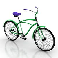
Bicycle Front Linkage Suspension
by GrabCAD
Last crawled date: 3 years, 1 month ago
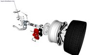
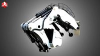
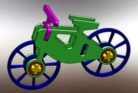
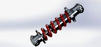
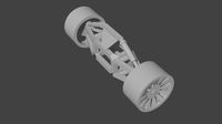
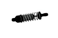
The present suspension assembly for bicycle may be summarised as the linkage assembly comprising fork, lower arms, intermediate arm, upper arm and shock absorber. The lower arm is pivotally secured to the coupler attached at the lower end of the fork. The upper arm is pivotally secured to the front fork. The intermediate arm being pivotally connected to the other ends of the lower arms and upper arm. The axle of the front wheel is inserted through the intermediate link eye and through the wheel hub, clamped in the journal. One eye of the shock damper is secured pivotally to the upper arm and the other eye is connected pivotally to the fork stem. Sex bolts and barrel nuts are used for pivoting the arms and shock absorber. However, any other barrel fasteners could be used. The anchors of the shock dampers are designed in a way that it secure itself in the slot and experiences minimum friction. The shock absorber wherein the upper pivoting bracket was optimized by providing holes. The FEA was performed to ensure the optimization. The lower arm, intermediate arm and upper arm are optimized by providing pockets in an attempt to reduce the material and make a sturdy suspension assembly. (Please find the attached 2D drafting for the same)
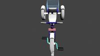
When the bicycle front wheel hits a bump, the front wheel tends to move up and down. This upward and downward movement of the wheel causes the swinging of the lower and upper arm, tends the intermediate arm to swing about the fork. The swinging movement of the upper arm about the pivot hence causes the coil spring of shock absorber to compress, absorbing the shocks and forces thereby. The transient analysis (FEA) was performed to simulate the same and results obtained could be seen in attached video and photos. The displacement was applied to the journal where the wheel axle is intended to be clamped. The displacement coordinates were found out using CATIA interface. It can be seen the stresses are acting in the coil spring on movement of the intermediate arm.
Being a Mechanical Engineering student, this was a small attempt to showcase my engineering, modelling and simulation skills.
Hope you guys like it :)
Similar models
grabcad
free

Suspension assembly
...suspension assembly
grabcad
assembly of gas charged coil over damper shock absorber with piggyback reservoir
grabcad
free

swing arm
...otorcycle to its body, allowing it to pivot vertically. ... the swingarm has also been used for the front suspension of scooters.
grabcad
free

Swing Arm
...nd atvs. it is used to hold the rear axle firmly, while pivoting vertically, to allow the suspension to absorb bumps in the road.
3dwarehouse
free
front suspension details (wheel, suspention knukle, hub bearing,absorber,lower control arm,brake disk, brake caliper,damper,pads)
...3dwarehouse
in model wheel, suspention knukle, hub bearing,absorber,lower control arm,brake disk, brake caliper,damper,pads.....
grabcad
free

Bike Swing Arm
...nd atvs. it is used to hold the rear axle firmly, while pivoting vertically, to allow the suspension to absorb bumps in the road.
grabcad
free

BSA B50 rear suspension Assembly
...bsa b50 rear suspension assembly
grabcad
step and iges files with frame , swinging arm , shock absorber ...
grabcad
free

Double Wishbone Suspension Design
...a wishbone or a-arm shape. 2. lower control arm: similar to the upper control arm, the lower control arm...
thingiverse
free
wltoys 12428 Feiyue FY03 Front Rocker Arm For Shock Absorber Damper by SatamaxPL
...wltoys 12428 feiyue fy03 front rocker arm for shock absorber damper by satamaxpl
thingiverse
damper absorber for fy03
grabcad
free

Suspension Front lower Arm
...suspension front lower arm
grabcad
suspension front lower arm and shock body
3dwarehouse
free
Shock absorber
...shock absorber
3dwarehouse
shocks! #absorber #damper #hydrolic #part #shock #suspension
Linkage
3d_export
$14
design model of linkage stepping mechanism
...mple and easy to obtain high manufacturing accuracy. connecting rod mechanism is widely used in various machines and instruments.
3d_export
$49
Liebherr R9250 Crane with Bucket
...main parts:9 name of the main parts: bucket bucket linkage catwalk and handrail for (crane) excavator boom excavator stick...
3d_export
$16
automatic box turnover equipment
...body by 180 degrees. at the same time, the linkage control with the original production line is adopted. the...
3d_export
$189

ford-8n tractor
...art".<br>rigged<br>on 3ds max file, the front wheels and their linkage are rigged.<br>what do you get?<br>included in this package:<br>* 3ds...
3d_export
$49
tesla cybertruck chassis
...cybertruck full chassis (battery pack, 3 motor setup, brakes, linkage, suspension, steering) built in blender and rende*** with cycles,...
3d_export
$149
jcb fastrac 8000 tractor
...exhaust pipe front and rear axle front pto and linkage system front tire front tire fenders front wheels glass...
3d_export
$99
tesla truck with chassis and trailer silver
...trailer and full chassis (battery pack, motor setup, brakes, linkage, suspension, steering) 3d model rendered with cycles in blender,...
3d_export
$99
tesla roadster yellow with chassis
...x with full chassis (battery pack, motor setup, brakes, linkage, suspension, steering) 3d model rendered with cycles in blender,...
3d_export
$99

tesla truck with chassis and trailer red
...trailer and full chassis (battery pack, motor setup, brakes, linkage, suspension, steering) 3d model rendered with cycles in blender,...
3d_export
$99

tesla model y awd white with chassis
...with full chassis (battery pack, 2 motor setup, brakes, linkage, suspension, steering) 3d model rendered with cycles in blender,...
Bicycle
3d_export
$15
bicycle
...bicycle
3dexport
simple bicycle
3ddd
$1
bicycle
...bicycle
3ddd
велосипед
bicycle
archibase_planet
free

Bicycle
...ibase planet
bicycle bike cycle two-wheeled bicycle
bicycle n080115 - 3d model (*.gsm+*.3ds+*.max) for exterior 3d visualization.
archibase_planet
free
Bicycle
...bicycle
archibase planet
bicycle cycle bike
bicycle n120411 - 3d model (*.3ds) for 3d visualization.
3d_export
$10
Bicycle
...bicycle
3dexport
bicycle toy or technique for children.
3d_export
$5
bicycle
...bicycle
3dexport
this is 3d model toy bicycle,
archibase_planet
free
Bicycle
...bicycle
archibase planet
bicycle cycle bike
bicycle n270309 - 3d model (*.3ds) for interior 3d visualization.
archibase_planet
free
Bicycle
...bicycle
archibase planet
bicycle cycle bike
bicycle n090211 - 3d model (*.3ds) for exterior 3d visualization.
archibase_planet
free
Bicycle
...bicycle
archibase planet
bicycle cycle bike
bicycle n011211 - 3d model (*.3ds) for exterior 3d visualization.
archibase_planet
free
Bicycle
...bicycle
archibase planet
bicycle cycle bike
bicycle n120608 - 3d model (*.gsm+*.3ds) for interior 3d visualization.
Suspension
3ddd
free
Circolo Suspension
...circolo suspension
3ddd
circolo , suspension
this is the circolo led suspension
3d_export
$20
suspension
...pension
3dexport
suspension it is used in bicycle, motorcycle; and many more object<br>rendering is done in photo view 360
3ddd
$1
Fieltebek suspension
...fieltebek suspension
3ddd
fieltebek , suspension
fieltebek
3d_export
free
suspension
...suspension
3dexport
3ddd
$1

Botti Suspension
...botti suspension
3ddd
botti
люстра botti suspension
turbosquid
$25

suspension
... available on turbo squid, the world's leading provider of digital 3d models for visualization, films, television, and games.
turbosquid
$8

suspension
... available on turbo squid, the world's leading provider of digital 3d models for visualization, films, television, and games.
turbosquid
$1
SUSPENSION
... available on turbo squid, the world's leading provider of digital 3d models for visualization, films, television, and games.
3ddd
$1
DELIGHTFULL MATHENY | SUSPENSION
... matheny , suspension
delightfull matheny | suspension
design_connected
$16
Vaeder Suspension
...vaeder suspension
designconnected
modular lighting instruments vaeder suspension computer generated 3d model.
Front
archibase_planet
free

Front
...front
archibase planet
facade front bluff
front 3d01a - 3d model (*.gsm+*.3ds) for interior 3d visualization.
3d_export
$5
front fork
...front fork
3dexport
front fork
3d_export
$5
Front Desk
...front desk
3dexport
modern and minimal reception front desk
3d_ocean
$4
Medical Front
...medical front
3docean
horror low medical
medical front
3d_ocean
$5
Front Desk
...front desk
3docean
desk front office reception
office reception counter or front desk. cad file and obj file included.
3ddd
free

Axor WaterDream by Front
...r , waterdream , front
axor waterdream by front
3d_export
$5
front nut eye
...front nut eye
3dexport
front nut eye
3d_export
$5
front screw eye
...front screw eye
3dexport
front screw eye
3d_export
$5

front clamping device
...front clamping device
3dexport
front clamping device
archive3d
free
Front 3D Model
...rchive3d
facade front bluff
front 3d01a - 3d model (*.gsm+*.3ds) for interior 3d visualization.