GrabCAD
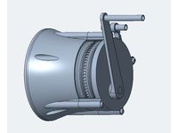
Better Gas Winch
by GrabCAD
Last crawled date: 1 year, 11 months ago
After building Gas Winch 1.0, I realized that I had to do better.
Goals:
*** Pull on the string to re-load winch (bearings are sized for gas spring compression loads which are much higher than output loads).
***Less fussy latch/release mechanism
***Cleaner outer appearance. Keep the fancy bits inside, provide fewer pinch points for fingers and such.
***Servo release. Especially attractive now that FIRST has taken servo power off the RoboRIO power supply :)
***Modular Design - more packaging options and more travel options to fit more end of match winching needs.
Regarding Modular Design:
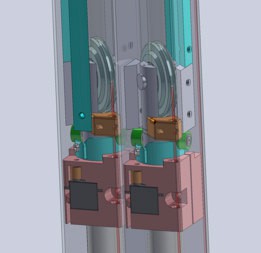
Each Gas Spring unit is designed to fit inside a 2"X2"X1/16" wall square tube (available from OnlineMetals.com).
Currently you get 48" of winch travel with 275lbs of force in a 2"X4"X32" package.
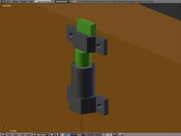
You could easily convert this to use the 16" stroke gas spring and get by with a single unit, assuming you can live with the 8 inches longer overall height and only 32" of winch travel at up to 275lbs of force. This package would be 2"X2"X40" << perhaps perfect for a boom that carries the hook that reaches the bar??? Another advantage of this configuration is that it would weigh perhaps 60-70% of the dual 12" version shown in the design.
Alternatively, you could also use 8" stroke gas spring and stack (3) of these units to get 8 inches shorter over all length and still have 48" of winch travel at up to 275lbs of force. Note this option has the down side of weighting ~50% more than the dual 12" configuration shown in the model. This package would be 2"X6"X24" << perhaps this would fit better in your robot???
A variation on this option would be to have the (3) 2"X2"X24" tubes arranged in an L shape each leg of the L being only 4", for a bounding box of 2"X4"X24" << again, maybe this is the perfect fit for your robot???
I don't recommend this but you may decide to build these 2"X2"X1/16" wall tubes into your robot chassis. In general, this seems like a crazy idea but in some cases it may be crazy like a fox.
YMMV. If you try this and end up sad, don't say I didn't warn you...
Regarding Servo Release:
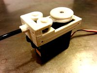
Servo release SHOULD be okay if bearing preformance is what I expect it to be. I need 2 mini-servos to release each gas spring but even with cheap Hitec servos I expect to have over 100% safety margin on unlatch/relatch torque.
Which reminds me, you need to power the servo to "relatch" once you have compressed the gas springs. FWIW, the net unlatch/relatch torque is approximatly the same. Unlatch has a larger moment arm but only 550lbs force. Relatching has 825lbs force but a smaller moment arm.
Finally on servos, I have used the very cheap HS-45HB AGTT Feather Servo $17 on Amazon - Hitec spec: 1in-lbs stall torque at 6V. There are other servos in similar sizes that have 2-4X the torque. Will investigate these should the margins start to worry me.
Servo Spec Here:
http://hitecrcd.com/products/servos/micro-and-mini-servos/analog-micro-and-mini-servos/hs-45hb-agtt-feather-servo/product
FWIW, I assumed a "coefficient of friction" for the ball bearing and the thrust bearing of 0.005 -- which seems reasonable based on web searching.
Regarding Manufacturing:
Many parts are designed to be 3D Printed.
There are some complex machined parts (the bottom block and the top pulley housing).
Bottom block is probably aluminum but will require a lot of machining (nothing fancy but there is a lot of metal to remove to provide the pivot for the bottom pulley).
Top Pulley Housing is probably Aluminum but may go steel. Still thinking.
Latch wedges are definitely steel. Maybe even hardened on the end surface to keep things from mushrooming over and raising unlatch forces.
Regarding Bearing:
Latch Bearing are 5905K210_STL NEEDLE-ROLLER BRNG
470lbs static load rating. 550 lbs max load share by 2 bearings. They never see gas spring's reloading force. Steel tube around the bearing keeps the outer race from deforming.
Thrust Bearings are 5909K320_THRUST NEEDLE-ROLLER BRNG
McMaster doesn't quote a static load spec but dynamic load rating is over 2000lbs. Should be fine even for 825lbs compression force for the gas spring.
Pulley Bearings are 60355K505_BALL BEARING
This one is kind of dicey on the bottom pulley. The rated static load is 535lbs. This does not really support the 825lbs compression load of the gas spring. BUT... I am hopeful that since the dynamic load is 1145lbs, and specs are often somewhat conservative and FIRST FRC is a low cycle type application, we can get through a season without incident. Not a great plan but it is all I have got unless I can find another bearing that fits. For Example, I can almost make 60355K506 fit even though it is a little wider (0.281" vs 0.250"). It has a 730lbs static rating. (Done. Update 2017-01-06)
The good news is the upper pulley uses 2 bearings so no worries at all on that front.
Not yet in the design:
Not shown are 10-24 countersunk flathead screws that are running up and down the outside of the 2"X2" tube. The idea is that these flush screws will allow for a "truck" to slide on the outside of the tube to provide a well defined motion for the hook or whatever you use to lift the robot. (Some screws shown. Update 2017-01-06)
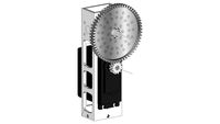
Also not shown are the gear teeth on the servo gear and the unlatch tube. They are "standard" 32DP 20 Degree Pressure Angle gears (10T and 48T respectively). The gears on modeled as cylinders with the standard OD. If you look a the models closely, I have also indicated the Root Diameter and the so called "Pitch Circle" with a very small groove in the edge of the part. I will be updated the CAD to have the true gear profiles soon. (Done. Update 2017-01-06)
Comments welcome.
UPDATE 2017-01-06:
***Added actual gear teeth to servo gear (but spline is still faked)
***Added actual gear teeth to unlatch tube
***Reduced gap between latch roller and latch plate
***Added some 10-24 flat head screws (but not all)
***Changed Bottom Block to have in "integral axle" after talking with CNC source -- makes the part much much better in function (in exchange for making it harder to machine)
***Changed to larger bottom pulley bearing. Still not 100% within spec for compressing the gas spring loads of 825 lbs. but it comes close 735lbs
Still to do:
***Put in remaining screws
***CAD actual Servo Spline and Servo Screw
***Make 8" travel version
***Make 16" travel version
***Make a new ZIP file and upload it
Dr. Joe J.
P.S. Zip file is a SolidWorks PackAndGo (professional edition -- sorry I don't have educational version available to me).
Goals:
*** Pull on the string to re-load winch (bearings are sized for gas spring compression loads which are much higher than output loads).
***Less fussy latch/release mechanism
***Cleaner outer appearance. Keep the fancy bits inside, provide fewer pinch points for fingers and such.
***Servo release. Especially attractive now that FIRST has taken servo power off the RoboRIO power supply :)
***Modular Design - more packaging options and more travel options to fit more end of match winching needs.
Regarding Modular Design:
Each Gas Spring unit is designed to fit inside a 2"X2"X1/16" wall square tube (available from OnlineMetals.com).
Currently you get 48" of winch travel with 275lbs of force in a 2"X4"X32" package.
You could easily convert this to use the 16" stroke gas spring and get by with a single unit, assuming you can live with the 8 inches longer overall height and only 32" of winch travel at up to 275lbs of force. This package would be 2"X2"X40" << perhaps perfect for a boom that carries the hook that reaches the bar??? Another advantage of this configuration is that it would weigh perhaps 60-70% of the dual 12" version shown in the design.
Alternatively, you could also use 8" stroke gas spring and stack (3) of these units to get 8 inches shorter over all length and still have 48" of winch travel at up to 275lbs of force. Note this option has the down side of weighting ~50% more than the dual 12" configuration shown in the model. This package would be 2"X6"X24" << perhaps this would fit better in your robot???
A variation on this option would be to have the (3) 2"X2"X24" tubes arranged in an L shape each leg of the L being only 4", for a bounding box of 2"X4"X24" << again, maybe this is the perfect fit for your robot???
I don't recommend this but you may decide to build these 2"X2"X1/16" wall tubes into your robot chassis. In general, this seems like a crazy idea but in some cases it may be crazy like a fox.
YMMV. If you try this and end up sad, don't say I didn't warn you...
Regarding Servo Release:
Servo release SHOULD be okay if bearing preformance is what I expect it to be. I need 2 mini-servos to release each gas spring but even with cheap Hitec servos I expect to have over 100% safety margin on unlatch/relatch torque.
Which reminds me, you need to power the servo to "relatch" once you have compressed the gas springs. FWIW, the net unlatch/relatch torque is approximatly the same. Unlatch has a larger moment arm but only 550lbs force. Relatching has 825lbs force but a smaller moment arm.
Finally on servos, I have used the very cheap HS-45HB AGTT Feather Servo $17 on Amazon - Hitec spec: 1in-lbs stall torque at 6V. There are other servos in similar sizes that have 2-4X the torque. Will investigate these should the margins start to worry me.
Servo Spec Here:
http://hitecrcd.com/products/servos/micro-and-mini-servos/analog-micro-and-mini-servos/hs-45hb-agtt-feather-servo/product
FWIW, I assumed a "coefficient of friction" for the ball bearing and the thrust bearing of 0.005 -- which seems reasonable based on web searching.
Regarding Manufacturing:
Many parts are designed to be 3D Printed.
There are some complex machined parts (the bottom block and the top pulley housing).
Bottom block is probably aluminum but will require a lot of machining (nothing fancy but there is a lot of metal to remove to provide the pivot for the bottom pulley).
Top Pulley Housing is probably Aluminum but may go steel. Still thinking.
Latch wedges are definitely steel. Maybe even hardened on the end surface to keep things from mushrooming over and raising unlatch forces.
Regarding Bearing:
Latch Bearing are 5905K210_STL NEEDLE-ROLLER BRNG
470lbs static load rating. 550 lbs max load share by 2 bearings. They never see gas spring's reloading force. Steel tube around the bearing keeps the outer race from deforming.
Thrust Bearings are 5909K320_THRUST NEEDLE-ROLLER BRNG
McMaster doesn't quote a static load spec but dynamic load rating is over 2000lbs. Should be fine even for 825lbs compression force for the gas spring.
Pulley Bearings are 60355K505_BALL BEARING
This one is kind of dicey on the bottom pulley. The rated static load is 535lbs. This does not really support the 825lbs compression load of the gas spring. BUT... I am hopeful that since the dynamic load is 1145lbs, and specs are often somewhat conservative and FIRST FRC is a low cycle type application, we can get through a season without incident. Not a great plan but it is all I have got unless I can find another bearing that fits. For Example, I can almost make 60355K506 fit even though it is a little wider (0.281" vs 0.250"). It has a 730lbs static rating. (Done. Update 2017-01-06)
The good news is the upper pulley uses 2 bearings so no worries at all on that front.
Not yet in the design:
Not shown are 10-24 countersunk flathead screws that are running up and down the outside of the 2"X2" tube. The idea is that these flush screws will allow for a "truck" to slide on the outside of the tube to provide a well defined motion for the hook or whatever you use to lift the robot. (Some screws shown. Update 2017-01-06)
Also not shown are the gear teeth on the servo gear and the unlatch tube. They are "standard" 32DP 20 Degree Pressure Angle gears (10T and 48T respectively). The gears on modeled as cylinders with the standard OD. If you look a the models closely, I have also indicated the Root Diameter and the so called "Pitch Circle" with a very small groove in the edge of the part. I will be updated the CAD to have the true gear profiles soon. (Done. Update 2017-01-06)
Comments welcome.
UPDATE 2017-01-06:
***Added actual gear teeth to servo gear (but spline is still faked)
***Added actual gear teeth to unlatch tube
***Reduced gap between latch roller and latch plate
***Added some 10-24 flat head screws (but not all)
***Changed Bottom Block to have in "integral axle" after talking with CNC source -- makes the part much much better in function (in exchange for making it harder to machine)
***Changed to larger bottom pulley bearing. Still not 100% within spec for compressing the gas spring loads of 825 lbs. but it comes close 735lbs
Still to do:
***Put in remaining screws
***CAD actual Servo Spline and Servo Screw
***Make 8" travel version
***Make 16" travel version
***Make a new ZIP file and upload it
Dr. Joe J.
P.S. Zip file is a SolidWorks PackAndGo (professional edition -- sorry I don't have educational version available to me).
Similar models
grabcad
free

Gas Winch
...th...
stay tuned.
also, latest zip file is a pack and go of the solidworks files and they include drawings (very simple ones).
grabcad
free

NASA Challenge cam latch
...e torsion spring and released by contact with mating component. spiral surface translates rotary motion to compression at joint.
thingiverse
free
Spring-Loaded Door Latch by abrokadabra
...r cylinder" pieces.
.
at current scales, this should require a spring with 3/8" diameter and 1.5 to 2" length.
thingiverse
free
Standard Servo Winch, cable, string puller by fastmike75
...ps. anyway, i thought this little winch was kind of cool. it is simple, easy to print and should have many practical uses. enjoy!
3dwarehouse
free
Actobotics Servo Tube Arm gearbox
...sired torque and rotation angle maximum. this is model spg785a-5 servo with 7:1 gear ratio at 1100 oz-in of torque. #robot #servo
thingiverse
free
Double Winch by TheEngineer_
...uminium tubes (8mm outer diameter)
1 ballbearing 608 zz
1 torque spring (made from thick wire)
grease for all bearings and gears
grabcad
free

FRC Inverted Swerve
...modeled in onshape for practice. more compact than the similar modules available for sale. simple mounting for 2"x1" or...
thingiverse
free
Quick release spool holder by rockpaperlizardspock
... slotted flange) and a lock nut on the spring side (pictured with 2 nuts locked together because i don't have any nyloc nuts)
thingiverse
free
Dual Drive extruder by Rundercaster
...ent any ideas you have)
edit: 29/01/2018:
added thread so you can attach the bowden tube also tube can go through up to the gears
grabcad
free

2-axis Torque and Thrust Sensor Biaxial Load Cell
...on torque as well as tension and compression force. forsentek model ft2e-e
reference: http://www.forsentek.com/prodetail_473.html
Winch
3d_export
$10
winch
...winch
3dexport
turbosquid
$15
winch
...ty free 3d model winch for download as 3ds, ige, obj, and 3dm on turbosquid: 3d models for games, architecture, videos. (1355394)
3ddd
$1

Faro Winch
...t lamphttp://www.faro.es/es/productos/winch-lampara-colgante-marron/
polyrate: 23679
в архиве присутствуют fbx и obj.
turbosquid
$30
Winch
...ree 3d model winch for download as ma, max, obj, fbx, and stl on turbosquid: 3d models for games, architecture, videos. (1368556)
3ddd
$1

Faro Winch
...://www.faro.es/es/productos/winch-lampara-colgante-con-peso-marron/
polyrate: 238187
в архиве присутствуют fbx и obj.
3ddd
$1

Faro Winch
...ttp://www.faro.es/es/productos/winch-lampara-aplique-marron-h-350mm/
polyrate: 13307
в архиве присутствуют fbx и obj.
3ddd
$1

Faro Winch
...ttp://www.faro.es/es/productos/winch-lampara-aplique-marron-h-460mm/
polyrate: 13687
в архиве присутствуют fbx и obj.
turbosquid
$15
Rope Winches
...squid
royalty free 3d model rope winches for download as max on turbosquid: 3d models for games, architecture, videos. (1415993)
turbosquid
$10

Winche(cabrestante)
...ee 3d model winche(cabrestante) for download as fbx and blend on turbosquid: 3d models for games, architecture, videos. (1376679)
turbosquid
$12
Stern Winch
...y free 3d model stern winch for download as max, fbx, and obj on turbosquid: 3d models for games, architecture, videos. (1591899)
Gas
archibase_planet
free
Gas
...gas
archibase planet
kitchen range gas stove cooker
gas - 3d model (*.gsm+*.3ds) for interior 3d visualization.
archibase_planet
free
Gas-stove
...e
archibase planet
gas-stove gas cooker kitchen-range gas stove
gas-stove - 3d model (*.gsm+*.3ds) for interior 3d visualization.
archibase_planet
free
Gas stove
...ase planet
gas stove kitchen-range gas-stove gas cooker
gas stove n280711 - 3d model (*.gsm+*.3ds) for interior 3d visualization.
archibase_planet
free

Gas stove
...e planet
gas stove gas cooker kitchen-range gas-stove
gas stove siemens n230912 - 3d model (*.3ds) for interior 3d visualization.
archibase_planet
free
Gas stove
...ase planet
gas stove kitchen-range gas-stove gas cooker
gas stove n201211 - 3d model (*.gsm+*.3ds) for interior 3d visualization.
archibase_planet
free
Gas stove
...ase planet
gas stove kitchen-range gas-stove gas cooker
gas stove n210512 - 3d model (*.gsm+*.3ds) for interior 3d visualization.
archibase_planet
free
Gas stove
...ase planet
gas stove gas cooker kitchen-range gas-stove
gas stove n170912 - 3d model (*.gsm+*.3ds) for interior 3d visualization.
archibase_planet
free
Gas stove
...ase planet
gas stove gas cooker kitchen-range gas-stove
gas stove n310313 - 3d model (*.gsm+*.3ds) for interior 3d visualization.
archibase_planet
free

Gas stove
...ase planet
gas stove gas cooker kitchen-range gas-stove
gas stove n110814 - 3d model (*.gsm+*.3ds) for interior 3d visualization.
archibase_planet
free

Gas stove
...ase planet
gas stove gas cooker kitchen-range gas-stove
gas stove n111014 - 3d model (*.gsm+*.3ds) for interior 3d visualization.
Better
3ddd
$1

Мозаика Better B-MOS D1
...os d1
3ddd
better , мозаика
мозаика better b-mos d1.
розтайленая мною.
+ бамп
+ рефлеккт
turbosquid
$19

BETTER THAN CHOCOLATE SOFA
... better than chocolate sofa for download as max, obj, and fbx on turbosquid: 3d models for games, architecture, videos. (1144132)
3d_export
$5

Soviet Tank T-150
...t-150 3dexport simple tank model. in project texture are better ...
archive3d
free
Polycarbonate 3D Model
...polycarbonate plastic polycarbonate sheet a little bit oversized for better ...
3d_export
$20
Terminator
...a robot created by skynet to defeat the resistance. better watch the movie if you haven’t seen it...
3d_export
free
simple grass
...simple grass scene with procedural texture for grass, is better swaps the texture of grass by...
3d_export
$5

picture-mirror
...father,for the bath,it is desirable to make out of wood,better than...
3ddd
$1

APLLES with wood vase
...3ddd яблоко zip archive contain fbx model too, for better textures import to 3d software. kind...
3d_export
$5
vinyl record player
...size 295x260mm without any materials (just standart grey for better ...
3ddd
$1

Armchair 400
...armchair 400, designed by alvar aalto in 1936 and better known as tank. pelt coat idea by...