Thingiverse
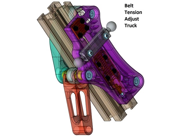
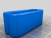
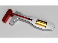
Belt Tension Adjust Truck for SeeMeCNC Ball Joint System and 1"x1" Extrusion by slonold
by Thingiverse
Last crawled date: 3 years ago
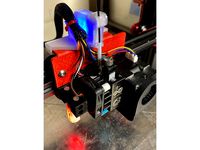
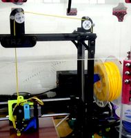
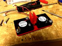
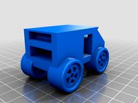
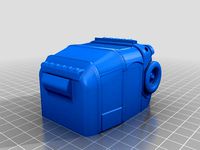
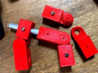
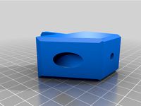
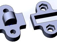
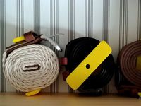
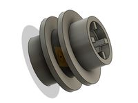
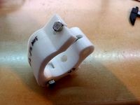
This carriage was inspired by Trick Laser's Trick Truck and a desire to have an easy, reliable and repeatable method of adjusting belt tension. While it is far from trick, the Belt Tension Adjust Truck is tight (much tighter than the molded carriages), fairly light at about 90g including the back shell, utilizes twin eccentric bushings (printable) to precisely set carriage clamping force and incorporates an easy to use belt tension mechanism.
Note that this truck requires OpenBuilds style Mini V Wheels (with extra Precision Shims) and is for use with 1" x 1" slotted extrusion.
Also note that as well as eating up some of your time, these trucks will eat about 25mm or so of Z height.
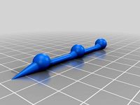
If you go to the trouble of making these trucks, the aluminum Machined Ball Joint "Barbells" from SeeMeCNC are strongly recommend as flex in the plastic ones appears to be the next largest source of motion in the system after slop in the spring loaded molded carriages. In addition, the aluminum barbells are quite true whereas this is not necessarily the case for the plastic ones which can create lack of parallelism and effector tilt problems as well as wide variation in end stop offsets if you use multiple hot ends.
Carbon Arms from Trick Laser are highly recommended.
Parts to Purchase (Note: if you are bereft of bolts see also tool section before ordering)
Running Gear
Mini (15.23mm/0.600" OD) V Wheels Qty 9
Available from MakerParts, OpenBuilds and of course a variety of suppliers on AliExpress including Fussnor
Precision Shims (5mm ID x 8mm OD x 1mm Height) - TOTAL required QTY 27Each Wheel Requires 3!! Carefully check how many shims are included with the wheels from your supplier to determine how many additional shims are required.
i.e. Fussnor, MakerParts, OpenBuilds
5mm x 40mm Socket Head Cap Screw Qty 9Note: Recommend cutting a 50mm bolt down to 40mm in order to get a longer unthreaded shank for a more plastic friendly bearing surface..
5mm Lock Nut Qty 9
Ball Joint Attachment
3mm x 18 or 20mm Button or Socket Head Cap Screw Qty 6(for aluminum barbell)or
3mm x 16 or 18mm Button or Socket Head Cap Screw Qty 6(for plastic barbell).
3mm Lock Nut Qty 6
3mm Washer Qty 6
End Stop Adjustment
3mm x 16 to 20mm Flat Head Screw Qty 3(hex drive recommended)
3mm x 2.5mm Thick Plain Nut Qty 6
Belt Clamps
2.5mm x 10mm Nylon Pan Head Screw Qty 12
2.5mm x 8mm Nylon Pan Head Screw Qty 12
2.5mm Nylon Plain Nuts Qty 24(metal screws +/- lock nuts may be substituted but the screws need to be trimmed by ~ 1mm).
Tension Adjuster
2.5mm x 16mm Socket Head Cap Screw Qty 3
2.5mm Lock Nut Qty 3
2.5mm "DIN125" (5mm OD) Nylon Washer/Spacer Qty 3
Optional End Stop Switch Mounting Hardware Upgrade for Max V2
M2.5 x 18 or 20mm Socket Head Caps Screw Qty 6
M2.5 Lock Nut Qty 6
M2.5 Washer Qty12
Printed Parts Note that dimensional accuracy is important. See instructions for specifics
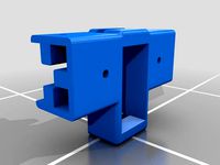
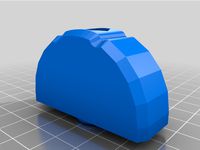
Body - Qty 3Recommend material with a higher flexural modulus such as PLA (i.e.PETG not recommended). Support required. Brim recommended as the wheel bosses are the only bed contact points. Strong cooling recommended to avoid curling as the wheel boss features gradually taper into the body. If possible, (i.e. Slic3r) slow speed considerably for the final layers associated with the barbell mount boss layers to minimize ovality. Overall it is probably better to print at a lower speed. Extrusion Width 0.3 to 0.4mm recommended. Shell Thickness should be about 0.9 to 1mm. Infill 15% Honeycomb. Layer Height 0.2mm or less.
Back_Shell - Qty 3As above, except Infill 10%
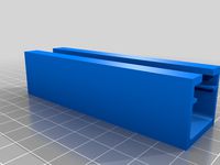
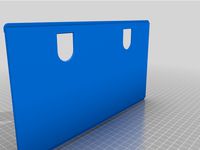
Adjuster_Clamp - Qty 3Recommend PETG for layer adhesion and toughness. Support Required. Extrusion Width 0.3 to 0.4mm recommended. Shell Thickness should be about 0.9 to 1mm. Infill 20% Honeycomb. Layer Height 0.1mm or less.
Fixed_Clamp - Qty 3As above, except support not required.
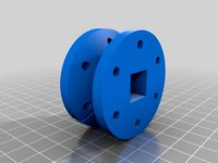
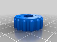
Eccentric - Qty 6Recommend ABS for natural lubricity and ease of "machining" to size. Extrusion Width 0.3 to 0.4mm recommended. Shell Thickness should be about 0.9 to 1mm. Infill 50% Honeycomb. Layer Height 0.2mm.TEST PRINTING TO MATCH SIZE TO YOUR 5/16 OR 8MM "BORING TOOL" IS STRONGLY RECOMMENDED. See Prepare Eccentric section of Instructions.
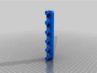
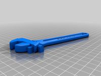
Wrench - Qty 1.Any rigid material. Extrusion Width 0.3 to 0.4mm recommended. Shell Thickness should be about 0.9 to 1mm. Infill 20% Honeycomb. Layer Height 0.2mm.
Recommended ToolsDrill Bits
2.5mm
3mm
1/4" or 6.5mm
Reamers (Note: could substitute end mills, drill bits, bits of emery tape wrapped around a shaft etc.)
5mm
5/16" or 8mm
Optional tools for optimizing aluminum barbell sockets
1/4" 4 Flute End Mill
Counter Sink suitable for 1/4" hole.
Ablating Devices
Riffler or similar small file set
1" bastard, aluminum or similar coarse flat file
Emery Tape 200 - 300 grit
Knifes
Reasonably stout and sharp hobby knife or similar
Hex Drivers
2mm
4mm
Sockets and Wrenches
5mm Wrench or Socket (if upgrading end stop switch hardware)
5.5mm Open Ended Wrench
8mm Nut Driver or Thin Walled Socket
Screw Drivers
Small Phillips (cross head)
Small (3 to 4mm width) Flat
Pliers
Medium Slip Joint
Small Needle Nose
Measuring Instruments
Caliper
A method of measuring belt deflection force to 1 - 2 kgfi.e. Hanging,Fish,Luggage Scale
Power Tools
Variable Speed Drill
Fixtures and other Handy Items
2.5mm x 20mm or so fully threaded Socket Head Cap Screw
3mm x 25mm or so fully threaded Socket Head Cap Screw
5mm x 20mm or so fully threaded Socket Head Cap Screw
5mm Lock Nut to be sacrificed as a poor persons lathe fixture
4 or 5mm width x 200mm or so length plastic cable tie
1-2" 6mm GT2 Belt Scrap
Firmware (SeeMeCNC Repetier)
The inner face (mounting surface for the Ball Joint barbell) distance from the Delta Radius (i.e. 200mm for a MaxV2) matches that of the molded carriage. Consequently, the Horizontal Carriage Offset distance does not need to be changed if you already have molded carriages (i.e. 26.5mm for a MaxV2). However the aluminum Machined Ball Joint Carriages have 1mm more of horizontal offset than the plastic barbells so if you are upgrading to the aluminum ones you need to add this distance (i.e. 27.5mm Horizontal Carriage Offset for a MaxV2).
Instructions
Dimension Check
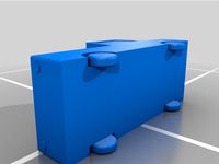
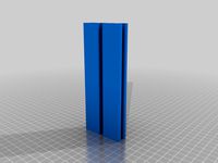
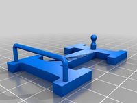
See below for major dimensions, the width (37.5mm) across the two parallel sides at the level of the barbell mount posts is critical for proper functioning of the eccentric wheel adjustment. Best to be within +/- 0.2mm. If the mount posts print a little oval, the major axis should ideally be at least 6.35mm.
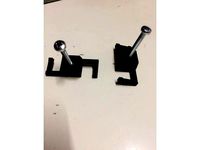
Prepare Barbells
Placing a chamfer on the sockets (A) will provide a little relief for the mounting posts where they rise from the body. Size sockets to 1/4" (C) to facilitate fitment.
Clear the Extrusion Tracks on Body and Back Shell
Remove support, then clean up any debris with a course file. Start with the bodies. Remove enough material to achieve a thickness of 10.5mm at the top of the body and 9.5mm at the bottom. Use your eyeball calipers to achieve a similar level of finish on the Back Shells.
Size Barbell Mounting Posts
Probably a good idea to get the posts covered up before they suffer any insults. Measure the posts carefully, the model is sized slightly large to ensure enough material for a good fit. Use a folded over strip of emery tape to work diameter down towards 6.35mm. Work both posts evenly to maintain centre distance and horizontal alignment. This is important to achieve a light press fit and avoid dread effector tilt. Be sure to keep an even dimension along the length of the post and remove (just) any protrusions from the surface were the barbell will seat against the body. As you approach dimension, check the fit regularly as described below in order to avoid the lament "i sanded it twice and it is still loose..."
Place Barbells
Test fit the posts one at a time, the goal is a light press fit. The barbell should slide down to within 2 or 3mm of the body with minimal effort. DO NOT FORCE (A). The reward for a partially jammed on barbell will likely be broken posts and a 4 hour reprint penalty (one might be able to drill and tap a 3mm thread and then place a bolt from the the backside through the length of the post to save the day). Once both posts are sized, apply a little lubricant (B) and test fit (C). There should be just a little resistance with 2 - 3mm to go (D), if this is the case, press the barbell with conviction to seat it fully and test for firmness (E).
Size Post Holes and Prepare Nut Sockets
Start with the 2mm drill and work up to 3mm (A). Be sure you are drilling true and are centred on the backside (B). Chamfer (C) and remove any support debris from the socket (D).
Place Barbell Nuts and Bolts
Prepare a longer M3 bolt, washer and M3 Lock Nut as shown (B), a little lubricant may be useful. Pull the nut into the socket taking care to achieve good alignment. Press the nut well into the socket (C). Install an 18mm (aluminum barbell) and seat nut firmly (D). Ensure bolt does not protrude about surface of extrusion track.
Install End Stop Adjusting Screw
While the 3mm drill bit is still in the drill motor, size the end stop screw hole (~20mm deep) to 3mm (A). Clean any debris from the captive nut slot (5.5mm x 2.5mm) (B). Position a 3mm plain nut (C) and carefully seat with pliers. Take care to avoid rotation of the nut. Otherwise you will be doing surgery on the fixed belt clamp. Run a plain nut up close to the head of the flat head 3mm screw and install.
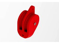
Install Fixed (Top) Belt Clamp
Mount up the 2.5mm drill bit. Size all 8 belt clamp holes to 2.5mm(A), as well as the holes in the fixed belt clamp (B). Remove any debris from the fixed belt clamp receptacle (C). Jump down to next step and then return. Once nuts are placed (see below) place a belt scrap in the belt groove (D), install clamp with 2.5mm x 10mm plastic screws and check for protrusion (E), trim if necessary (F).
Install Belt Clamp Nuts
Place a M2.5mm plastic nut on a longer M2.5mm bolt such that the bolt protrudes ~2mm beyond the nut (A) and gently seat into socket maintaining alignment (B). Place a M3 socket head cap screw over the protruding bolt (B) and then PRESS the nut into the socket (C) to achieve a good seat (D).
Prepare Adjusting Clamp
Remove support debris from Adjusting Belt Clamp (A). Check fit and smooth motion of a M2.5mm plastic screw in groove (B). Clean slot sufficiently so that with a little applied seating force, the screw travels smoothly along the full distance of the slot and the head does not protrude (C). Remove any debris and surface protrusions from the adjusting clamp receptacle (D) so that the clamp slides smoothly along its travel whilst applying a firm finger squeeze.
Install Adjusting Clamp
Size hole in end of adjusting clamp with 2.5mm drill bit. Remove debris from slot (5mm x 4.5mm) for captive nut (B). Position M2.5 Lock Nut in slot with lock ring facing belt teeth and seat full (C). Place a M2.5 washer (max OD 5mm) on the M2.5 x 16mm socket head cap screw and install adjusting clamp (D).
Prepare Eccentric Boss Faces
Identify the junction of the built in support for the eccentric boss faces of both the Body and Back Shell (A). Remove squarely with a sharp and stiff blade (B). Taking great care to maintain a perpendicular face, remove the small joining castellations (C). It should only take a light stroke or two (i filed it twice and...") to reach the required dimensions of 14mm for the body (D) and 8.5mm for the back shell (E).
Prepare Wheel Bolt Holes and Eccentric Bore
Using (ideally) a 5mm reamer and a little lubricant, size the two fixed wheel boss holes in both the body and back shell to 5mm (A). Remove any swarf (B). Size the inner bore of the eccentric to 5mm (C). You may want to hold the eccentric with something safer than the printed wrench if you are boring with something less friendly than a straight reamer but take care not to crush the eccentric. Size the bolt hole in the eccentric boss to a minimum of 6mm and no more than 1/4" (D).
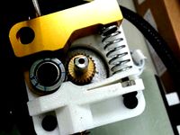
Prepare EccentricFirst bore the eccentric boss receptacle in the body and back shell to 5/16" or 8mm with (ideally) a reamer (B). Test fit the eccentric (A), if loose reprint - a snug fit is important. A little too tight is perfect as now there is an excuse to turn the eccentric boss down to size with a Poor Person's Lathe (C) using fixturing along the lines shown (D). Any day involving a lathe operation is a good day indeed. The goal is to have the eccentric require a moderate amount of finger force in order to rotate the eccentric when fully seated (F). Once fairly satisfied with the rotational fit, check the depth fit of the eccentric (E) and deepen the receptacle (B) if required until the eccentric just seats (F).
Install Nuts for Fixed Wheel Bolts in Back Shells
Start (A), press (B), seat (C).
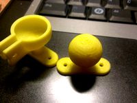
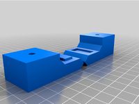
Eccentric Orientation
The dot on the eccentric face denotes the face furthest from the eccentric bore. A little ink on the dot may be useful. Not the outward orientation of the dot when the eccentric in the tightest position. When the dot is positioned towards the centre of the extrusion track the eccentric is in the loosest position which is where it should be for installation.
Mini V Wheel Assembly
Note that there must be a shim between the two bearings. Some suppliers ship the wheels with bearings already installed but without a shim. Inspect carefully. The wheel bolts need to be drawn up tightly. Consequently, the shim between the bearings is essential in order to avoid excessive axial bearing load. Remove a bearing from preassembled wheels and install the shim if necessary.
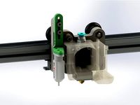
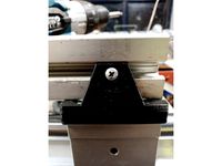
Truck Installation
Prepare a truck by using a M5 x 40mm socket head cap screw and M5 lock nut to mount the eccentric wheel. Note that there must be a shim on EACH side of the wheel (A). Be sure that the dot on both eccentrics is facing inwards (A). Gently snug the nut, splay the truck and position the truck on the extrusion so that the end stop adjusting screw winds up facing upwards (B)! Rotate truck halves into position (C). Install the fixed wheels with a shim on each side of the wheel and tighten firmly (D).
Set Eccentric WheelAfter the fixed wheel bolts are tight, set the tightness of the eccentric wheel bolt so that eccentric can be turned with the wrench but not freely (A). Minimize displacement of the eccentrics by holding the hex driver fixed and rotating the nut Place the wrench with the handle facing upwards (B) and rotate down (whilst pushing to engage the wrench firmly onto both eccentrics) (C) to obtain the truck tightness that your heart desires. Ensure both eccentrics turn together (D). Tighten eccentric wheel bolt and recheck truck motion. A couple of iterations may be required.
Install Lower Belt - Step 1
Loosen adjusting clamp screws until just engaged by a couple of threads (A). Loosen adjusting screw until the clamp is just able to reach the top of its travel (B). Place a little curl in the belt and feed it through the central hole in the body. On a good day the belt end can be caught with a screw driver (C). With the clamp in the lower position, feed the belt underneath (D). A little lever action should handily feed the belt under the clamp (E & F).
Install Lower Belt - Step 2
Ensure belt is fully seated in clamp (A). Turn screws in evenly to just take up the slack (B). Pull down on belt to position clamp at top of travel (C). Tighten screws just a little to give the clamp a bit more bite (D).
Install Upper Belt
Loosen fixed clamp screws until just engaged and fully unseat clamp (A). Place a curve in a mid size cable tie and use it to fish the upper belt through the centre hole in the body (B). Use a screw driver to feed the belt under the clamp (C) until the belt comes out the top and can be nabbed (D). Use needle nose pliers in conjunction with the end stop adjusting screw (carefully) as a fulcrum to take all the slack and then some out of the belt and GENTLY snug the screws - the teeth will hold belt as long as the clamp is in the general vicinity (E). Verify the bite is good (F).
Position End Stop Switches
Position end stop switches as shown. If replacing original mounting bolts with M2.5, the mounting and switch holes may need sizing with a 2.5mm drill bit.
.
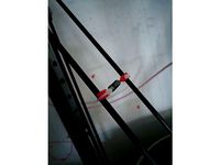
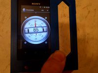
Tension Belts
Position truck at top, check tension at middle against fixed distance reference. Tension at will!! GENTLY snug screws when finished.
Note that this truck requires OpenBuilds style Mini V Wheels (with extra Precision Shims) and is for use with 1" x 1" slotted extrusion.
Also note that as well as eating up some of your time, these trucks will eat about 25mm or so of Z height.
If you go to the trouble of making these trucks, the aluminum Machined Ball Joint "Barbells" from SeeMeCNC are strongly recommend as flex in the plastic ones appears to be the next largest source of motion in the system after slop in the spring loaded molded carriages. In addition, the aluminum barbells are quite true whereas this is not necessarily the case for the plastic ones which can create lack of parallelism and effector tilt problems as well as wide variation in end stop offsets if you use multiple hot ends.
Carbon Arms from Trick Laser are highly recommended.
Parts to Purchase (Note: if you are bereft of bolts see also tool section before ordering)
Running Gear
Mini (15.23mm/0.600" OD) V Wheels Qty 9
Available from MakerParts, OpenBuilds and of course a variety of suppliers on AliExpress including Fussnor
Precision Shims (5mm ID x 8mm OD x 1mm Height) - TOTAL required QTY 27Each Wheel Requires 3!! Carefully check how many shims are included with the wheels from your supplier to determine how many additional shims are required.
i.e. Fussnor, MakerParts, OpenBuilds
5mm x 40mm Socket Head Cap Screw Qty 9Note: Recommend cutting a 50mm bolt down to 40mm in order to get a longer unthreaded shank for a more plastic friendly bearing surface..
5mm Lock Nut Qty 9
Ball Joint Attachment
3mm x 18 or 20mm Button or Socket Head Cap Screw Qty 6(for aluminum barbell)or
3mm x 16 or 18mm Button or Socket Head Cap Screw Qty 6(for plastic barbell).
3mm Lock Nut Qty 6
3mm Washer Qty 6
End Stop Adjustment
3mm x 16 to 20mm Flat Head Screw Qty 3(hex drive recommended)
3mm x 2.5mm Thick Plain Nut Qty 6
Belt Clamps
2.5mm x 10mm Nylon Pan Head Screw Qty 12
2.5mm x 8mm Nylon Pan Head Screw Qty 12
2.5mm Nylon Plain Nuts Qty 24(metal screws +/- lock nuts may be substituted but the screws need to be trimmed by ~ 1mm).
Tension Adjuster
2.5mm x 16mm Socket Head Cap Screw Qty 3
2.5mm Lock Nut Qty 3
2.5mm "DIN125" (5mm OD) Nylon Washer/Spacer Qty 3
Optional End Stop Switch Mounting Hardware Upgrade for Max V2
M2.5 x 18 or 20mm Socket Head Caps Screw Qty 6
M2.5 Lock Nut Qty 6
M2.5 Washer Qty12
Printed Parts Note that dimensional accuracy is important. See instructions for specifics
Body - Qty 3Recommend material with a higher flexural modulus such as PLA (i.e.PETG not recommended). Support required. Brim recommended as the wheel bosses are the only bed contact points. Strong cooling recommended to avoid curling as the wheel boss features gradually taper into the body. If possible, (i.e. Slic3r) slow speed considerably for the final layers associated with the barbell mount boss layers to minimize ovality. Overall it is probably better to print at a lower speed. Extrusion Width 0.3 to 0.4mm recommended. Shell Thickness should be about 0.9 to 1mm. Infill 15% Honeycomb. Layer Height 0.2mm or less.
Back_Shell - Qty 3As above, except Infill 10%
Adjuster_Clamp - Qty 3Recommend PETG for layer adhesion and toughness. Support Required. Extrusion Width 0.3 to 0.4mm recommended. Shell Thickness should be about 0.9 to 1mm. Infill 20% Honeycomb. Layer Height 0.1mm or less.
Fixed_Clamp - Qty 3As above, except support not required.
Eccentric - Qty 6Recommend ABS for natural lubricity and ease of "machining" to size. Extrusion Width 0.3 to 0.4mm recommended. Shell Thickness should be about 0.9 to 1mm. Infill 50% Honeycomb. Layer Height 0.2mm.TEST PRINTING TO MATCH SIZE TO YOUR 5/16 OR 8MM "BORING TOOL" IS STRONGLY RECOMMENDED. See Prepare Eccentric section of Instructions.
Wrench - Qty 1.Any rigid material. Extrusion Width 0.3 to 0.4mm recommended. Shell Thickness should be about 0.9 to 1mm. Infill 20% Honeycomb. Layer Height 0.2mm.
Recommended ToolsDrill Bits
2.5mm
3mm
1/4" or 6.5mm
Reamers (Note: could substitute end mills, drill bits, bits of emery tape wrapped around a shaft etc.)
5mm
5/16" or 8mm
Optional tools for optimizing aluminum barbell sockets
1/4" 4 Flute End Mill
Counter Sink suitable for 1/4" hole.
Ablating Devices
Riffler or similar small file set
1" bastard, aluminum or similar coarse flat file
Emery Tape 200 - 300 grit
Knifes
Reasonably stout and sharp hobby knife or similar
Hex Drivers
2mm
4mm
Sockets and Wrenches
5mm Wrench or Socket (if upgrading end stop switch hardware)
5.5mm Open Ended Wrench
8mm Nut Driver or Thin Walled Socket
Screw Drivers
Small Phillips (cross head)
Small (3 to 4mm width) Flat
Pliers
Medium Slip Joint
Small Needle Nose
Measuring Instruments
Caliper
A method of measuring belt deflection force to 1 - 2 kgfi.e. Hanging,Fish,Luggage Scale
Power Tools
Variable Speed Drill
Fixtures and other Handy Items
2.5mm x 20mm or so fully threaded Socket Head Cap Screw
3mm x 25mm or so fully threaded Socket Head Cap Screw
5mm x 20mm or so fully threaded Socket Head Cap Screw
5mm Lock Nut to be sacrificed as a poor persons lathe fixture
4 or 5mm width x 200mm or so length plastic cable tie
1-2" 6mm GT2 Belt Scrap
Firmware (SeeMeCNC Repetier)
The inner face (mounting surface for the Ball Joint barbell) distance from the Delta Radius (i.e. 200mm for a MaxV2) matches that of the molded carriage. Consequently, the Horizontal Carriage Offset distance does not need to be changed if you already have molded carriages (i.e. 26.5mm for a MaxV2). However the aluminum Machined Ball Joint Carriages have 1mm more of horizontal offset than the plastic barbells so if you are upgrading to the aluminum ones you need to add this distance (i.e. 27.5mm Horizontal Carriage Offset for a MaxV2).
Instructions
Dimension Check
See below for major dimensions, the width (37.5mm) across the two parallel sides at the level of the barbell mount posts is critical for proper functioning of the eccentric wheel adjustment. Best to be within +/- 0.2mm. If the mount posts print a little oval, the major axis should ideally be at least 6.35mm.
Prepare Barbells
Placing a chamfer on the sockets (A) will provide a little relief for the mounting posts where they rise from the body. Size sockets to 1/4" (C) to facilitate fitment.
Clear the Extrusion Tracks on Body and Back Shell
Remove support, then clean up any debris with a course file. Start with the bodies. Remove enough material to achieve a thickness of 10.5mm at the top of the body and 9.5mm at the bottom. Use your eyeball calipers to achieve a similar level of finish on the Back Shells.
Size Barbell Mounting Posts
Probably a good idea to get the posts covered up before they suffer any insults. Measure the posts carefully, the model is sized slightly large to ensure enough material for a good fit. Use a folded over strip of emery tape to work diameter down towards 6.35mm. Work both posts evenly to maintain centre distance and horizontal alignment. This is important to achieve a light press fit and avoid dread effector tilt. Be sure to keep an even dimension along the length of the post and remove (just) any protrusions from the surface were the barbell will seat against the body. As you approach dimension, check the fit regularly as described below in order to avoid the lament "i sanded it twice and it is still loose..."
Place Barbells
Test fit the posts one at a time, the goal is a light press fit. The barbell should slide down to within 2 or 3mm of the body with minimal effort. DO NOT FORCE (A). The reward for a partially jammed on barbell will likely be broken posts and a 4 hour reprint penalty (one might be able to drill and tap a 3mm thread and then place a bolt from the the backside through the length of the post to save the day). Once both posts are sized, apply a little lubricant (B) and test fit (C). There should be just a little resistance with 2 - 3mm to go (D), if this is the case, press the barbell with conviction to seat it fully and test for firmness (E).
Size Post Holes and Prepare Nut Sockets
Start with the 2mm drill and work up to 3mm (A). Be sure you are drilling true and are centred on the backside (B). Chamfer (C) and remove any support debris from the socket (D).
Place Barbell Nuts and Bolts
Prepare a longer M3 bolt, washer and M3 Lock Nut as shown (B), a little lubricant may be useful. Pull the nut into the socket taking care to achieve good alignment. Press the nut well into the socket (C). Install an 18mm (aluminum barbell) and seat nut firmly (D). Ensure bolt does not protrude about surface of extrusion track.
Install End Stop Adjusting Screw
While the 3mm drill bit is still in the drill motor, size the end stop screw hole (~20mm deep) to 3mm (A). Clean any debris from the captive nut slot (5.5mm x 2.5mm) (B). Position a 3mm plain nut (C) and carefully seat with pliers. Take care to avoid rotation of the nut. Otherwise you will be doing surgery on the fixed belt clamp. Run a plain nut up close to the head of the flat head 3mm screw and install.
Install Fixed (Top) Belt Clamp
Mount up the 2.5mm drill bit. Size all 8 belt clamp holes to 2.5mm(A), as well as the holes in the fixed belt clamp (B). Remove any debris from the fixed belt clamp receptacle (C). Jump down to next step and then return. Once nuts are placed (see below) place a belt scrap in the belt groove (D), install clamp with 2.5mm x 10mm plastic screws and check for protrusion (E), trim if necessary (F).
Install Belt Clamp Nuts
Place a M2.5mm plastic nut on a longer M2.5mm bolt such that the bolt protrudes ~2mm beyond the nut (A) and gently seat into socket maintaining alignment (B). Place a M3 socket head cap screw over the protruding bolt (B) and then PRESS the nut into the socket (C) to achieve a good seat (D).
Prepare Adjusting Clamp
Remove support debris from Adjusting Belt Clamp (A). Check fit and smooth motion of a M2.5mm plastic screw in groove (B). Clean slot sufficiently so that with a little applied seating force, the screw travels smoothly along the full distance of the slot and the head does not protrude (C). Remove any debris and surface protrusions from the adjusting clamp receptacle (D) so that the clamp slides smoothly along its travel whilst applying a firm finger squeeze.
Install Adjusting Clamp
Size hole in end of adjusting clamp with 2.5mm drill bit. Remove debris from slot (5mm x 4.5mm) for captive nut (B). Position M2.5 Lock Nut in slot with lock ring facing belt teeth and seat full (C). Place a M2.5 washer (max OD 5mm) on the M2.5 x 16mm socket head cap screw and install adjusting clamp (D).
Prepare Eccentric Boss Faces
Identify the junction of the built in support for the eccentric boss faces of both the Body and Back Shell (A). Remove squarely with a sharp and stiff blade (B). Taking great care to maintain a perpendicular face, remove the small joining castellations (C). It should only take a light stroke or two (i filed it twice and...") to reach the required dimensions of 14mm for the body (D) and 8.5mm for the back shell (E).
Prepare Wheel Bolt Holes and Eccentric Bore
Using (ideally) a 5mm reamer and a little lubricant, size the two fixed wheel boss holes in both the body and back shell to 5mm (A). Remove any swarf (B). Size the inner bore of the eccentric to 5mm (C). You may want to hold the eccentric with something safer than the printed wrench if you are boring with something less friendly than a straight reamer but take care not to crush the eccentric. Size the bolt hole in the eccentric boss to a minimum of 6mm and no more than 1/4" (D).
Prepare EccentricFirst bore the eccentric boss receptacle in the body and back shell to 5/16" or 8mm with (ideally) a reamer (B). Test fit the eccentric (A), if loose reprint - a snug fit is important. A little too tight is perfect as now there is an excuse to turn the eccentric boss down to size with a Poor Person's Lathe (C) using fixturing along the lines shown (D). Any day involving a lathe operation is a good day indeed. The goal is to have the eccentric require a moderate amount of finger force in order to rotate the eccentric when fully seated (F). Once fairly satisfied with the rotational fit, check the depth fit of the eccentric (E) and deepen the receptacle (B) if required until the eccentric just seats (F).
Install Nuts for Fixed Wheel Bolts in Back Shells
Start (A), press (B), seat (C).
Eccentric Orientation
The dot on the eccentric face denotes the face furthest from the eccentric bore. A little ink on the dot may be useful. Not the outward orientation of the dot when the eccentric in the tightest position. When the dot is positioned towards the centre of the extrusion track the eccentric is in the loosest position which is where it should be for installation.
Mini V Wheel Assembly
Note that there must be a shim between the two bearings. Some suppliers ship the wheels with bearings already installed but without a shim. Inspect carefully. The wheel bolts need to be drawn up tightly. Consequently, the shim between the bearings is essential in order to avoid excessive axial bearing load. Remove a bearing from preassembled wheels and install the shim if necessary.
Truck Installation
Prepare a truck by using a M5 x 40mm socket head cap screw and M5 lock nut to mount the eccentric wheel. Note that there must be a shim on EACH side of the wheel (A). Be sure that the dot on both eccentrics is facing inwards (A). Gently snug the nut, splay the truck and position the truck on the extrusion so that the end stop adjusting screw winds up facing upwards (B)! Rotate truck halves into position (C). Install the fixed wheels with a shim on each side of the wheel and tighten firmly (D).
Set Eccentric WheelAfter the fixed wheel bolts are tight, set the tightness of the eccentric wheel bolt so that eccentric can be turned with the wrench but not freely (A). Minimize displacement of the eccentrics by holding the hex driver fixed and rotating the nut Place the wrench with the handle facing upwards (B) and rotate down (whilst pushing to engage the wrench firmly onto both eccentrics) (C) to obtain the truck tightness that your heart desires. Ensure both eccentrics turn together (D). Tighten eccentric wheel bolt and recheck truck motion. A couple of iterations may be required.
Install Lower Belt - Step 1
Loosen adjusting clamp screws until just engaged by a couple of threads (A). Loosen adjusting screw until the clamp is just able to reach the top of its travel (B). Place a little curl in the belt and feed it through the central hole in the body. On a good day the belt end can be caught with a screw driver (C). With the clamp in the lower position, feed the belt underneath (D). A little lever action should handily feed the belt under the clamp (E & F).
Install Lower Belt - Step 2
Ensure belt is fully seated in clamp (A). Turn screws in evenly to just take up the slack (B). Pull down on belt to position clamp at top of travel (C). Tighten screws just a little to give the clamp a bit more bite (D).
Install Upper Belt
Loosen fixed clamp screws until just engaged and fully unseat clamp (A). Place a curve in a mid size cable tie and use it to fish the upper belt through the centre hole in the body (B). Use a screw driver to feed the belt under the clamp (C) until the belt comes out the top and can be nabbed (D). Use needle nose pliers in conjunction with the end stop adjusting screw (carefully) as a fulcrum to take all the slack and then some out of the belt and GENTLY snug the screws - the teeth will hold belt as long as the clamp is in the general vicinity (E). Verify the bite is good (F).
Position End Stop Switches
Position end stop switches as shown. If replacing original mounting bolts with M2.5, the mounting and switch holes may need sizing with a 2.5mm drill bit.
.
Tension Belts
Position truck at top, check tension at middle against fixed distance reference. Tension at will!! GENTLY snug screws when finished.
Similar models
thingiverse
free
5mm Flex Shaft Coupler by 3DNoodle
...-acto,diagonal cutters,etc...
additional parts required:
3mm x 16mm screws (qty 2)
3mm nuts (qty 2)
3mm washers (qty 2, optional)
thingiverse
free
FR7Heavy v#.# by stynkebutt
...rs (if 9mm are unavailable, suggest using 8mm)
misc. hardware
3mm press nuts; 9; https://www.mcmaster.com/94100a110 or equivalent
thingiverse
free
X Slide T Belt Adjuster by G3DBuilder
...equested. the pma clamp utilizes 2-56 x 1/2" screws for the top cover and 4 m4 x 8mm to attach to the linear bearing blocks
thingiverse
free
Hemera Aluminium adaptor plate V2, CR-10S Pro by Portzal
... position and install the bottom wheel on the bolt,
adjust eccentric nut and tighten fixing bolt nut.
reinstall and tighten belt.
thingiverse
free
Cherry pi III Mini V Wheel Carriage for OpenBuild with Cable tightener by mikes3ds
...ointys design 8mm balls, and for the rexroth/motedis see this link.http://forums.reprap.org/read.php?178,361141,470341#msg-470341
thingiverse
free
Anycubic i3 Mega Y-axis Belt Tensioner
... m4 nuts
b) 2 x 40mm m4 screws (allen head din-912)
c) 2 x 20mm m3 screws
d) 1 x 12mm m3 screw
e) 1 x m3 nut
f) 3d printed parts
thingiverse
free
Hemera CR-10S Pro Conversion
...djust eccentric nut.
reinstall and tighten belt.
i have uploaded a photo of how i held the plate in a vice to bend the belt tabs.
thingiverse
free
Flex Filament Pulley Guide for Lulzbot Taz 5 by billyd
...idler creates a bigger gap at the pulley. but not so much that the filament can pull through.
this is for 2.85mm or 3mm filament.
thingiverse
free
X axis end clamp by bunjatec
...ll need to print :
1x end clamp
2x end clamp fixings
the clamp then holds the ends of the x stage rods and stops them poking out.
thingiverse
free
Anet e10 / e12 - Improved X-carriage - Belt parallizer - BLtouch by Nystao
...:
m3 nut: qty: 6 for carriage + 2 for bltouch holder
chc m3x25 qty:2
chc m3x16 qty:4 for belt holders + 2 for bltouch bracket
Slonold
thingiverse
free
Garmin 910XT 22mm Aerobar Extension Mount by slonold
...nt watch - note that strap does not have to be tight - spare your spring pins
adjust angle and fix by gently snugging set screws.
thingiverse
free
Crabby Cap Zesty Nimble SeeMeCNC HE280/Accelerometer Mount by slonold
... the ptfe tube should contact the bottom of the filament guide on centre without distortion. re-trim the ptfe tube if necessary.
thingiverse
free
Nimble Gimbal - Gimbaling Extruder Motor Mount for Zesty Nimble by slonold
...?). with the x60 i went with a 0.3mm nozzle and 0.2mm extrusion width, 3 perimeters, 0.125 layer height and 5 top/bottom layers.
thingiverse
free
Prometheus Mount for SeeMeCNC Rostock Ball Joint Platform +/- Accelerometer Option by slonold
...ive to the clamp plate like a clam shell.
be sure to seat bowden tube and insert ptc retainer before mounting accelerometer board
thingiverse
free

PanelDue 5" and Duet 2 Mounts for SeeMeCNC Rostock Max V2 by slonold
...phery of the onyx bed. some tape to hold the bed and template down will be your friend whilst you outline the bed plate cut out.
thingiverse
free
Nimble Gimbal For 2020 Delta Frame by quadcells
...i saw slonold's nimble gimbal and liked the idea. slonold did a great job on his design. i needed...
thingiverse
free
Nimble Gnu - System to Adapt the Zesty Nimble Extruder to a Prometheus V2 Hotend Mounted to a SeeMeCNC Balljoint Effector Platform with Accelerometer Probe PCB by slonold
...ter, strap down the whip.
remember to revisit your slicer retraction settings. it is a whole new world without the bowden tube.
thingiverse
free
Zesty Nimble V2 Breech Replica by kulfuerst
...p3 - bearing offset by 0.3 mm i like slonold#39;s naming system and adapted it here. i have not...
Seemecnc
thingiverse
free

Rostock hotend seemecnc by Wrangler
...rostock hotend seemecnc by wrangler
thingiverse
this thing was made to connect hotend seemecnc to rostock platform.
thingiverse
free

SeeMeCNC Keychain by johnoly99
...seemecnc keychain by johnoly99
thingiverse
no mas!
thingiverse
free

SeeMeCNC Rocket by johnoly99
...seemecnc rocket by johnoly99
thingiverse
no mas!
thingiverse
free
SeeMeCNC 3D Printer Model by ReginaFabricam
...seemecnc 3d printer model by reginafabricam
thingiverse
this is a model of the seemecnc orion delta 3d printer
thingiverse
free
SeeMeCNC H2 NamePlate (Blank) by CapperLabs
...seemecnc h2 nameplate (blank) by capperlabs
thingiverse
seemecnc h2 nameplate without any lettering autocad drawing and .stl
thingiverse
free

SeeMeCNC Plastic Bearings by johnoly99
...seemecnc plastic bearings by johnoly99
thingiverse
no mas!
thingiverse
free

Mosquito for SeeMeCNC Artemis by emoser
...and some rostock printeres.
you will need https://www.sliceengineering.com/collections/accessories/products/threaded-stem-adapter
thingiverse
free
SeeMeCNC EZstruder cooler by Disconnector
...r on my seemecnc rostock max was running very hot (like burn my hand hot!) so i designed a dual 40mm fan mount. all cool now :-)
thingiverse
free

SeeMeCNC H-1 90 Degree Clamp by johnoly99
...seemecnc h-1 90 degree clamp by johnoly99
thingiverse
seemecnc h-1 90 degree clamp
thingiverse
free

SeeMeCNC H-1 Table by johnoly99
...seemecnc h-1 table by johnoly99
thingiverse
no mas!
X1
thingiverse
free

Artillery X1 by scorpio_man30ro
...artillery x1 by scorpio_man30ro
thingiverse
artillery x1
thingiverse
free

Artillery X1 by scorpio_man30ro
...artillery x1 by scorpio_man30ro
thingiverse
artillery x1
thingiverse
free
Bell X1 Plane
...bell x1 plane
thingiverse
bell x1 rocket powered plane
thingiverse
free

Kane X1 by garayonah
...kane x1 by garayonah
thingiverse
test upload of kane x1 prototype
thingiverse
free

sidewider x1 firmware by Xavierart26
...sidewider x1 firmware by xavierart26
thingiverse
firmware for sidewider x1
thingiverse
free
Signature x1 robot by HuangAro
...signature x1 robot by huangaro
thingiverse
signature x1 robot
thingiverse
free

Labists X1 / Easythreed X1 Cura Profile by fabiofilippini
... stl file to level the bed.
as the bed is not heated (and there's a little of backslash in the z axis) i usually use the raft
thingiverse
free
Sidewinder X1 cover left
...sidewinder x1 cover left
thingiverse
cover for the sidewinder x1 on the left hand sight
thingiverse
free
Sidewinder x1 Filament Guide
...sidewinder x1 filament guide
thingiverse
filament guide for sidewinder x1!
no screws needed!
thingiverse
free
Ring X1 by rafaellacerda
...se
ring x1 free 3d print model
apocalypse scene.
inner circumference:
mm - 49,32
inches - 1,94
photo and printing: myminifactory
Truck
thingiverse
free
Cyber Truck
...cyber truck
thingiverse
truck
thingiverse
free
truck by SWJTUyuhui
...truck by swjtuyuhui
thingiverse
truck
thingiverse
free

Truck by MalkaRu
...truck by malkaru
thingiverse
truck
enjoy
thingiverse
free

Truck keychain
...truck keychain
thingiverse
truck keychain
thingiverse
free
TRUCK by PHKVSMITO
...truck by phkvsmito
thingiverse
its a truck
thingiverse
free
Chevy truck
...chevy truck
thingiverse
chevy truck
thingiverse
free
truck by NArdo
...truck by nardo
thingiverse
toy truck
thingiverse
free
Truck by arty321
...truck by arty321
thingiverse
just a simple truck.
thingiverse
free
truck by zack_holes
...truck by zack_holes
thingiverse
a truck i designed on inventor
thingiverse
free
Truck by Lestico
...truck by lestico
thingiverse
3d modeled truck to allow a cellphone
Joint
thingiverse
free
Joint by WillandMrData2
...joint by willandmrdata2
thingiverse
joint, marijuana joint, dak,cannabis cigarette,
thingiverse
free
Joint by Ajfel
...joint by ajfel
thingiverse
joint
thingiverse
free

sizer joint
...sizer joint
thingiverse
sizer
joint
thingiverse
free

Ball Joint
...ball joint
thingiverse
ball joint
thingiverse
free
Joint by powellwe
...joint by powellwe
thingiverse
simple joint structure
thingiverse
free

Joint cover
...joint cover
thingiverse
a simple threaded cover for your joints!
thingiverse
free

Cardanic joint
...cardanic joint
thingiverse
fully functional 3d printed cardanic joint
thingiverse
free
Joint by haya_dev
...joint by haya_dev
thingiverse
this joint attaches your smartphone to pc.
there are clearances for felt pads.
thingiverse
free
Locking Joint
...0mm pipe, or wood dowl at 10 different angles.
due to the gearing, these joint lock and can take a surprising amount of pressure.
thingiverse
free
Joint by Holmstrup
...joint by holmstrup
thingiverse
45x45 profile joint to sbr25 laniary rails for my cnc router.
Tension
thingiverse
free

tensioner by Gincso0808
...tensioner by gincso0808
thingiverse
test tensioner
thingiverse
free
Tensioner
...tensioner
thingiverse
print in upright position. works great on any extrusion
thingiverse
free
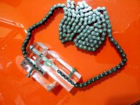
tensioner by GMFerrari
...the y-axis belt with a chain 6mm because the belt was now deformed by tension.
in the photos you can see how i made the tensioner
thingiverse
free
rope tensioner by Muffin256
...rope tensioner by muffin256
thingiverse
rope tensioner
thingiverse
free
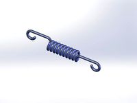
tension spring by mikehubka
...tension spring by mikehubka
thingiverse
tension spring
thingiverse
free
Belt tensioner. by IvanFjodorovich
...belt tensioner. by ivanfjodorovich
thingiverse
belt tensioner.
thingiverse
free
Clothesline Tensioner by hervstein
...clothesline tensioner by hervstein
thingiverse
tensioner for clothesline ropes.
thingiverse
free
Chain Tensioner by tromano32
...chain tensioner by tromano32
thingiverse
simple chain tensioner
thingiverse
free
Hercules Extruder Tensioning
...g.
3d printed tensioning screw ideally should be printed with 100% infill and
the tensioning plate can be printed with 30% infill
thingiverse
free
The delta tensioning by RuiJan1
...the delta tensioning by ruijan1
thingiverse
this is a delta prenter the arm tensioning
Extrusion
thingiverse
free

Extrusion Endcap
...extrusion endcap
thingiverse
extrusion endcap sized for misumi extrusions
thingiverse
free
Eyeball (Dual Extrusion and Single Extrusion) by Pollak3DPrintingPros
...n be dual extrusion, multi extrusion, and single extrusion.
designed with meshmixer. eyeball.stl is the single extrusion version.
thingiverse
free
Vega Extrusion-Servo-Extrusion by Cjeshiva
...vega extrusion-servo-extrusion by cjeshiva
thingiverse
zoop
thingiverse
free
signback extrusion
...signback extrusion
thingiverse
model of aluminium signback extrusion.
thingiverse
free

Easter eggs simply extrusion and dual extrusion by Uwe94
...by uwe94
thingiverse
easter eggs simply extrusion and dual extrusion.
the files with dual extruder end in xxxxx_dua; xxxxx_dub
thingiverse
free
1560 extrusion 150mm
...1560 extrusion 150mm
thingiverse
1560 extrusion 150mm
thingiverse
free
Octahedral extrusion by nevitdilmen
...octahedral extrusion by nevitdilmen
thingiverse
extrusions from octahedron
thingiverse
free
Extrusion bracket by theedee
...extrusion bracket by theedee
thingiverse
3-way bracket for 'u' shaped extrusion
thingiverse
free

1515 Extrusion by cudatox
...1515 extrusion by cudatox
thingiverse
something resembling 1515 extrusion. most parameters are customizable, including length.
thingiverse
free
Dovetail Extrusion 50x50x50 by shags
...dovetail extrusion 50x50x50 by shags
thingiverse
dovetail extrusion 50x50x50
Belt
thingiverse
free
belt
...belt
thingiverse
belt sleeve for 35mm wide..
use tpu or tpu95
gcode ready
thingiverse
free

Belt hanger for mission belt by maburke
...belt hanger for mission belt by maburke
thingiverse
hanger for mission belt- hangs belt nicely on the closet rod
thingiverse
free
Belt Hanger (For Belts With a Stud) by SamuelSVD
...belt hanger.
this belt hanger works by placing the stud on the belt in the hole, then hang the hanger.
yep, it's that simple.
thingiverse
free
Belt hanger for Trakline belt by tomasf
...belt hanger for trakline belt by tomasf
thingiverse
a hanger for a single trakline belt.
thingiverse
free

Belt clip for 9 mm belt by papat400
...belt clip for 9 mm belt by papat400
thingiverse
remix the belt lock gt2 for a 9mm belt
thingiverse
free
Belt Rack
...belt rack
thingiverse
belt hanger
thingiverse
free
Belt Holder
...belt holder
thingiverse
a simple belt holder.
thingiverse
free
Hermes belt buckle for 31mm belt by Hubiro
...hermes belt buckle for 31mm belt by hubiro
thingiverse
hermes belt buckle for 31mm belt
perfect to order as metal print :-)
thingiverse
free
Bugatti belt buckle for 31mm belt by Hubiro
...t buckle for 31mm belt by hubiro
thingiverse
bugati belt buckle made for 31mm hermes belt.
perfect to order as a metal print :-)
thingiverse
free
Belt tensioner for GT2 belts by Endlesscnc
...oner little different.
after print you will need a:
m3 nut
m3 x10+ (screw length your choice)
is for the gt2 belt with 6mm width
Ball
thingiverse
free
ball in ball in ball in ball by Syzguru11
...ww.thingiverse.com/syzguru11/collections/balls
(donations appreciated, but not necessary. my things are free and will always be).
thingiverse
free

ball in a ball in a ball in a ball by Simon_Vance
...in a ball by simon_vance
thingiverse
i just put together a random thing because i was bored and it was just a 20 minute project.
thingiverse
free

Ball in Ball by PatrickSalvador
...ball in ball by patricksalvador
thingiverse
ball in ball
thingiverse
free
Ball in a ball by zakw
...ball in a ball by zakw
thingiverse
ball within a ball
thingiverse
free
Ball in Ball by DevinWilcox
... by devinwilcox
thingiverse
break ball loose and enjoy!
big thanks to gkewley for the picture of the white printed ball in ball.
thingiverse
free
Ball in a Ball in a Ball - by Flightcache by Flightcache
...lls.
2015 | printed the ball in ball in ball with my mendel 90 with support sliced with slic3r and it is working fine. 50% size
thingiverse
free
ball in ball 2020
...://www.thingiverse.com/thing:2754149
also check out my oyher ball designshttps://www.thingiverse.com/syzguru11/collections/balls
thingiverse
free

Ball for ball bearing by Quanrbit
...l bearing by quanrbit
thingiverse
this remix is designed for single balls in ball bearings
7.3mm/0.287" diameter
using brim
thingiverse
free
twisted ball in ball in ba.... by Syzguru11
...twisted ball in ball in ba.... by syzguru11
thingiverse
twisted ball in ball in ba....
thingiverse
free
twisted ball in ball in ba.... by Syzguru11
...twisted ball in ball in ba.... by syzguru11
thingiverse
twisted ball in ball in ba....
System
thingiverse
free

Coordinate system
...coordinate system
thingiverse
coordinate system
thingiverse
free
ACRO SYSTEMS DRAG CHAIN SYSTEM by dragonfire81m
...acro systems drag chain system by dragonfire81m
thingiverse
chain link mounting system for acro system openbuilds
thingiverse
free

Circulatory System
...circulatory system
thingiverse
made in a 3d design software
designed for students
circulatory system based on images
thingiverse
free
Clutch system
...clutch system
thingiverse
clutch system inspired from lego technics kit
print with default settings
thingiverse
free

Gear system test-Systeme d'engrenage Test by CPS007
...gear system test-systeme d'engrenage test by cps007
thingiverse
gear system test-systeme d'engrenage test
13cm7cm7cm
thingiverse
free
Pulley System by LeapFrog_3D
...pulley system by leapfrog_3d
thingiverse
pulley system
thingiverse
free
System Block by CryoShift
...system block by cryoshift
thingiverse
system block
thingiverse
free
System administrator by Diodmag
...system administrator by diodmag
thingiverse
system administrator, sculpting
thingiverse
free
L.A. Systems by Bjorn175
...l.a. systems by bjorn175
thingiverse
l.a. systems mold
thingiverse
free
Decken Montage-system
...decken montage-system
thingiverse
decken montage-system
Adjust
thingiverse
free
Adjustable Wrench
...adjustable wrench
thingiverse
working adjustable hand wrench.
thingiverse
free
PPG adjustable propellers adjusting device by x3x3x
...ppg) adjustable propellers adjusting device. 95 mm blade width. android phone, apple, symbian os. applications for free download.
thingiverse
free
Adjustable foot
...adjustable foot
thingiverse
just another adjustable foot for m5 screw (better if is self-locking nut).
diameter 20mm
thingiverse
free
Adjustment Handle by adamdthornton
...adjustment handle by adamdthornton
thingiverse
adjustment handle
thingiverse
free

Adjustable foot by denis4
...adjustable foot by denis4
thingiverse
adjustable leg
thingiverse
free
Adjustable Extruded by CruiseLee
...adjustable extruded by cruiselee
thingiverse
adjustable extruded
thingiverse
free
adjustable spanner by stevehaines
...adjustable spanner by stevehaines
thingiverse
adjustable spanner
thingiverse
free
Adjustable Wrench by AdamsLab
...h by adamslab
thingiverse
this is an adjustable wrench.
the top jaws slide into the main body, and you use the nut to adjust it.
thingiverse
free

Lawnmower adjustment handle
...lawnmower adjustment handle
thingiverse
lawnmower adjustment handle
thingiverse
free

Adjustable Frame by Quinventor
...adjustable frame by quinventor
thingiverse
an adjustable picture frame
1
thingiverse
free

Magic Token +1/+1 & -1/-1 by Kilgara2B
...magic token +1/+1 & -1/-1 by kilgara2b
thingiverse
a magic the gathering token +1/+1 and -1/-1
thingiverse
free
MTG +1/+1 and -1/-1 counters by 4PStudiosGaming
...tudiosgaming
thingiverse
if you are in need of the 4pstudiosgaming +1/+1 and -1/-1 counters, then you came to the right page :-p
thingiverse
free

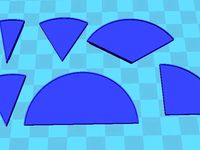
Fraction circle 1/2, 1/3, 1/4, 1/6, 1/8, 1/10, 1/12 by tfloveless
... 1/6, 1/8, 1/10, and 1/12 sized wedges as well as a circular base for them to fit onto. there are no labels on any of the pieces.
thingiverse
free
Adapter Syphon - 1 1/4" to 1 1/2" by _Stefano17_
...dapter for syphon - 1 1/4" to 1 1/2" h10,5mm
the project was realized with tolerances for printing with abs + tape ptf.
thingiverse
free
1 1/8" and or 1 1/5" headset press
...l fit both 1 1/8" and 1 1/5" bearing cups. i used a 3/8ths" threaded rod with nuts and thick washers on each end.
thingiverse
free
1-1/4" to 1-1/2" pipe cheeseborough clamp by aonomus
...design cheeseborough clamp for hanging lightfixtures and other items onto 1-1/4"-1-1/2" npt pipe. use at your own risk.
thingiverse
free
Shopping cart tokens 1€ 1$ 1£ by I_am_me
...them instead of money coin in your supermarket cart or in your swimming pool locker.
edit : updated 1£ coin with new dimensions
thingiverse
free
pipe thread adapter 1" to 1" 1/4 by Printerforever
...d adapter 1" to 1" 1/4 by printerforever
thingiverse
this is an adapter 1" to 1" 1/4 (male to male)
enjoy !
thingiverse
free

Playstation 2, 1:1 by Vitting
...playstation 2, 1:1 by vitting
thingiverse
made a 1:1 playstation 2.
thingiverse
free
Nesting Fraction Circle 1/2, 1/3, 1/4, 1/6, 1/8, 1/10, 1/12 V.2 by tfloveless
...re thinner and actually fit within each other to show equivalent fractions. also, check out the same version with braille (here).