Thingiverse

Barebones ATX PSU by Lucidwolf
by Thingiverse
Last crawled date: 3 years, 1 month ago
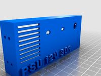
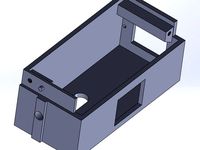
My pretty version of an ATX PSU to lab bench power supply. Follow the RepRap ATX to power supply (PSU) conversion guide for directions and warnings.
There seem to be enough PSU conversion cases/fittings here so why did I upload mine:
1.) I like simplicity so no lights and a clean mounting surface.
2.) None that I saw added what I feel is vital and that is an easy to check fuse system on the PSU.
3.) These are for my kids which like to see sparks and burn things up… I like to fuse the PSU under what each power rail is rated so the fuse blows before the box smokes…
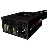
The parts I used were banana posts that you can find in any electronic components store. A mini fuse box for an ATV was used for that clean easy to inspect fuse box look. The two screws run through the case and the fuse box to attach the entire assembly. The ATX PSU I buy have to have a large fan and a physical power switch. (1 less thing to buy and wire)
Unfortunately every ATV fuse box I have purchased is slightly different so this would be best used as a reference part. (The ATV fuse box I used is not listed anymore on Amazon, I attached a picture what I found that was similar)
UPDATE 9/9/2017:
I had to make another PSU (and the box I could find was different again) and while doing that I thought I would learn about making a parametric model in FreeCAD that can survive some wild variable changes (See MKII FreeCAD file). The FreeCAD model has a spreadsheet with the parameters to fit any fuse box. (See attached picture for parameter names) It is also a good representation on how to make clean models that won’t break with parameter changes that drastically change the model because it uses Boolean operations that are relational to a geometric loft and not tied to model state. I use the word loft here liberally because in this model it’s just a square blue box set to variable a and b… (FreeCAD blue lines in sketcher are reference geometry)
Old walk through for CAD continues below
END UPDATE 9/9/2017
Steps for making this in CAD
Directions (x = horizontal, y = vertical, Z =towards the PSU)
1.) Sketch a rectangle the size of the PSU Side and extrude (pad) to depth (mine was 20mm) (XY plane +Z extrusion)
2.) Sketch a rectangle on the Z+ surface of the extruded rectangle on step 1 (XY plane with –Z cut)
a. The rectangle size should be centered with a (width – 2thickness, height – 2 thickness)
b. Cut (pocket) the rectangle into the pad in step 1 to (depth – thickness)
c. Note: I used 2mm for my thickness
3.) Sketch the location of the window into your box for the fuses with a cut through all (XY plane)
a. This is dependent on your fuse box
4.) Sketch the padups for the fuse box tabs (Internal face of cover +Z extrusion
a. Again dependent on your fuse box (extrude = depth – thickness of the fuse box tabs)
b. Make sure there is room to get your wires around your pad ups (My design was a little too tight sometimes
5.) Sketch the mounting holes for your fuse box
a. Again dependent on your fuse box
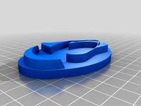
6.) Add the holes for the banana posts on the +Y surface (ZX plane)
a. I make mine r=4.1mm that way I don’t have to worry about drilling them out and they are loose tolerance hole and most posts are slightly oversized.
b. I do not usually make the posts have the standard 19.05mm (3/4”) spacing between holes for dual plugs. I force single plugs since I don’t want one of my kids bridging different voltage lines. (I only made it 1mm different to mess with them though.. >:D )
7.) I used automotive wire terminals to connect everything. (Blade ends at the fuse box and circle ends at the posts)
8.) To mount it match drill using the fitting into the side of the psu and run two machine screws with a nut. (Bonus points if you use Loctite or a lock nut on the nut.)
There seem to be enough PSU conversion cases/fittings here so why did I upload mine:
1.) I like simplicity so no lights and a clean mounting surface.
2.) None that I saw added what I feel is vital and that is an easy to check fuse system on the PSU.
3.) These are for my kids which like to see sparks and burn things up… I like to fuse the PSU under what each power rail is rated so the fuse blows before the box smokes…
The parts I used were banana posts that you can find in any electronic components store. A mini fuse box for an ATV was used for that clean easy to inspect fuse box look. The two screws run through the case and the fuse box to attach the entire assembly. The ATX PSU I buy have to have a large fan and a physical power switch. (1 less thing to buy and wire)
Unfortunately every ATV fuse box I have purchased is slightly different so this would be best used as a reference part. (The ATV fuse box I used is not listed anymore on Amazon, I attached a picture what I found that was similar)
UPDATE 9/9/2017:
I had to make another PSU (and the box I could find was different again) and while doing that I thought I would learn about making a parametric model in FreeCAD that can survive some wild variable changes (See MKII FreeCAD file). The FreeCAD model has a spreadsheet with the parameters to fit any fuse box. (See attached picture for parameter names) It is also a good representation on how to make clean models that won’t break with parameter changes that drastically change the model because it uses Boolean operations that are relational to a geometric loft and not tied to model state. I use the word loft here liberally because in this model it’s just a square blue box set to variable a and b… (FreeCAD blue lines in sketcher are reference geometry)
Old walk through for CAD continues below
END UPDATE 9/9/2017
Steps for making this in CAD
Directions (x = horizontal, y = vertical, Z =towards the PSU)
1.) Sketch a rectangle the size of the PSU Side and extrude (pad) to depth (mine was 20mm) (XY plane +Z extrusion)
2.) Sketch a rectangle on the Z+ surface of the extruded rectangle on step 1 (XY plane with –Z cut)
a. The rectangle size should be centered with a (width – 2thickness, height – 2 thickness)
b. Cut (pocket) the rectangle into the pad in step 1 to (depth – thickness)
c. Note: I used 2mm for my thickness
3.) Sketch the location of the window into your box for the fuses with a cut through all (XY plane)
a. This is dependent on your fuse box
4.) Sketch the padups for the fuse box tabs (Internal face of cover +Z extrusion
a. Again dependent on your fuse box (extrude = depth – thickness of the fuse box tabs)
b. Make sure there is room to get your wires around your pad ups (My design was a little too tight sometimes
5.) Sketch the mounting holes for your fuse box
a. Again dependent on your fuse box
6.) Add the holes for the banana posts on the +Y surface (ZX plane)
a. I make mine r=4.1mm that way I don’t have to worry about drilling them out and they are loose tolerance hole and most posts are slightly oversized.
b. I do not usually make the posts have the standard 19.05mm (3/4”) spacing between holes for dual plugs. I force single plugs since I don’t want one of my kids bridging different voltage lines. (I only made it 1mm different to mess with them though.. >:D )
7.) I used automotive wire terminals to connect everything. (Blade ends at the fuse box and circle ends at the posts)
8.) To mount it match drill using the fitting into the side of the psu and run two machine screws with a nut. (Bonus points if you use Loctite or a lock nut on the nut.)
Similar models
grabcad
free

ATX PSU Holder
...the default design is aimed at using 1mm thick steel plate, but you could convert to acrylic by changing the thickness parameter.
thingiverse
free

Wanhao i3 (v1) PSU Endcap by DevilZmods
...er supply mod for the wanhao i3.
has a mounting hole for the fuse box and power cable, and a hole to run a cable to your printer.
thingiverse
free

Prusa PSU Mount by QuantumConcepts
...than i had hoped. i should add more support or maybe increase the infill (i used 40%) to make this better. but for now, it works!
thingiverse
free

ATX PSU table mount by kumekay
...psu table mount by kumekay
thingiverse
i use atx psu as a lab power supply, so this one is mounted under the table with 2 screws
thingiverse
free

PC PSU Mount for 20mm Extrusion by nocut12
...u could probably just use only the front plate.
i've attached the sketchup files in case you need to make any modifications.
grabcad
free

dodecahedron scalable
...lanes then slice up a sphere to make the body.
there is one parameter (units) to determine size and one constant (golden ratio).
thingiverse
free

Mount power supply ATX PSU by vitos
...mount power supply atx psu by vitos
thingiverse
mount power supply atx psu
thingiverse
free

ATX power supply mount Anet A8 by r0mppa
...ers: 140x150x85
mount inner diameters 141x151x86
my psu sit snugly in the mount.
holes are done to fit original holes in anet a8.
thingiverse
free

Workbench DC Power Splitter & fuses & Atx 24 Minifit JR & Bannana Plug
...mble are per-designed in solid works to make it compact, and using the parts i got from electronics scrap or cheap chinese stuff.
thingiverse
free

ATX Power Supply Holder and Cable Box for Prusa i3 printer by grnnja
...ply to the frame and all the excess cables were a mess, so i built this box to attach the power supply and hide the pesky cables.
Lucidwolf
thingiverse
free

Spacer for Bottle Rinser by Lucidwolf
...er for bottle washer (https://www.thingiverse.com/thing:3064953)
thought i would post my hack freecad and stl if it helps others.
thingiverse
free

Otto_GIFS by Lucidwolf
...istory of the otto gifs robot click the remixed from designs to see a list of other creators that helped grow the otto community.
thingiverse
free

D300VS+ Dust Covers by Lucidwolf
...vertical slot based delta printers.
this is part of my upgrades to the ultibots d300vs+ https://www.thingiverse.com/thing:3089764
thingiverse
free

D300VS+ Modifications by Lucidwolf
...printers speed limit.
like most printers this is a work in progress.
still need to design and print
1.) led holders
2.) enclosure
thingiverse
free

Vorpal RubberBand Shoes by Lucidwolf
...t uses a rubber band, but this works pretty good for now. i only put the shoes on the four legs and keep the fighting arms free.
thingiverse
free

Putt Putt Clubs (Kid Sized) by Lucidwolf
...ated rod is a different size.
no supports and typical 20% infill. kept shell thickness at 1.2 (3x nozzle) for impact resistance.
thingiverse
free

Easy Delta Pie by Lucidwolf
...els. :)
need to design a delta cal launching device since i have so many of those disks...
maybe use the cali cats as targets...
thingiverse
free

Wire Rack Spool Clips by Lucidwolf
...s can modify it if they like. i was lazy so no sheet with variables, just two sketches, but every thing was constrained to 100%.
thingiverse
free

Otto DIY Accessories by Lucidwolf
...ct in the tree first. also you should be in the part design module to see the sketching tools.
plenty of guides online have fun.
thingiverse
free

Bunny Night Light Stand Fix (Bunny not Included) by Lucidwolf
...5.html
switch was reused and i shouldn’t have, might remix soon with a better switch and maybe a usb charger/internal lipo setup.
Barebones
3ddd
$1

Аккумуляторный фонарь в стиле ретро
...аккумуляторный фонарь в стиле ретро 3ddd фонарь , barebones фонарь forest (лесной) от студии...
archive3d
free

Lamp 3D Model
...model archive3d lamp kerosene lamp luminaire oil lamp lamp barebones forest lamp n161115 - 3d model (*.gsm+*.3ds) for interior...
thingiverse
free

Gaslands Barebones Bug - 1/64 by Tony_D
...gaslands barebones bug - 1/64 by tony_d
thingiverse
this is a 1/64 barebones bug for gaslands.
thingiverse
free

Gaslands Barebones Race Bug - 1/64 by Tony_D
...gaslands barebones race bug - 1/64 by tony_d
thingiverse
this is a barebones race bug for gaslands.
thingiverse
free

Gaslands Barebone 2020 Bronco - 1/64 by Tony_D
...bronco - 1/64 by tony_d thingiverse this is a barebones gaslands 2020...
thingiverse
free

Gaslands Barebones Charger SRT-8 - 1/64 by Tony_D
...gaslands barebones charger srt-8 - 1/64 by tony_d
thingiverse
this is a barebones dodge charger srt-8 for gaslands.
thingiverse
free

Vesa support mini pc barebone
...vesa support mini pc barebone
thingiverse
vesa mini pc support
thingiverse
free

Four drive array for aopen barebone by electropluma
...e four drive caddy for aopen barebone
this thing was made with tinkercad. edit it online https://tinkercad.com/things/dc1hcca7sdg
thingiverse
free

Gaslands Barebone Gasser (custom) 1/64 by Tony_D
...gasser (custom) 1/64 by tony_d thingiverse this is a barebones vehicle for gaslands. tires should snap in. let me...
thingiverse
free

Shuttle barebon psu coverplate by makibox850
...coverplate by makibox850 thingiverse coverplate for some shuttle xpc barebones ( this particular is from the sh-61-series, but many...
Atx
turbosquid
$100

Giant Atx 690
... available on turbo squid, the world's leading provider of digital 3d models for visualization, films, television, and games.
3ddd
free

ATX ZALMAN Z9 Plus
...㎜ fan x 1 (120㎜ blue led fan x 1 standard)
сверху 120㎜ /140㎜ fan x 2 (120ԩ
humster3d
$75

3D model of Vetex Sidewinder ATX 3000 Forklift 2011
... vetex sidewinder atx 3000 forklift 2011 in various file formats. all our 3d models were created maximally close to the original.
3d_export
$20

The Computer case 3D Model
...model 3dexport computer case big full super tower htpx atx the computer case 3d model mackandco 34251...
3d_ocean
$17
Computer Case
...computer case 3docean atx case computer corsair full game gaming pc psu full...
3d_export
$8

soporte para gpu
...actualmente instalado en un gabinete corsair spec alpha gabinete atx gaming con una asus turbo rtx 2060 se puede...
3ddd
free

Корпус Asus Vento Chassis TA-883 500W
...сбора компьютеров на базе материнских плат форматов atx и microatx подробнее:http://hard.rozetka.com.ua/asus_vento_chassis_ta883_500w/p161251/ код производителя ta-883 500w тип корпуса miditower материал...
sketchfab
$5

ATX Motherboard
...c block, modelled to scale,
atx form factor,
last update 21/06/21 - atx motherboard - buy royalty free 3d model by cavicom (@asi)
thingiverse
free

motherboard atx by joselcl98
...motherboard atx by joselcl98
thingiverse
motherboard model atx
thingiverse
free

ATX holder by diegocr
...atx holder by diegocr
thingiverse
holder to place an atx power under the table.
Psu
3d_ocean
$17
Computer Case
...3docean atx case computer corsair full game gaming pc psu full tower-like computer case model with 113946...
cg_studio
$9
Power Supply Unit PSU3d model
...d .fbx .lwo .ma .max .obj .xsi - power supply unit psu 3d model, royalty free license available, instant download after purchase.
thingiverse
free
PSU cover for 12v 30A PSU by Salti
...
cover for the "dangerous" end of a standard led psu
230v input, 2 x 12v outputs
supports psu width 11cm and height 5cm
thingiverse
free

psu holder by sta8atos
...psu holder by sta8atos
thingiverse
psu holder
thingiverse
free
psu stamp by astorck
...psu stamp by astorck
thingiverse
psu stamp
thingiverse
free

PSU Cover by Shojo
...psu cover by shojo
thingiverse
psu cover
thingiverse
free
PSU cover by chroja
...psu cover by chroja
thingiverse
psu cover
thingiverse
free

PSU Cover for 9,9 cm PSU Anet A8 by Wolverine_DH
...a8 by wolverine_dh
thingiverse
psu cover for 9.9sm psu optimal high for anet a8 screw holes, more side holes for diffrend psus.
thingiverse
free

Anet A8 PSU Fan (2017 PSU)
...coarse threaded fan screws. additionally 2 x m3x8mm machine screws needed to attach fan mount to psu. do not use long than 8mm.
thingiverse
free

SFX PSU to ATX PSU adapter by Kanashii
... atx format adapter so i made my own adapter. better use hard plastic to stick psu to pc's case without breaking the adapter.