Thingiverse

Backpack Part Cooler for FT-5 by CreativeSpark
by Thingiverse
Last crawled date: 3 years, 1 month ago
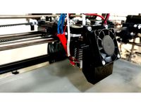
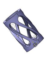
This is a part cooler for the Folgertech FT-5 R2 (reportedly does NOT work with R1). It mounts the blower behind the X axis belt and closer to the central axis of the X rail, which minimizes the mass hanging below the X rail and as a result, minimizes the wobble during rapid Y movements. The entire part weighs just 32 grams, and the wall thickness is designed at 0.75mm, which prints fine and is plenty sturdy even in PLA. The airflow has been directed internally by turning vanes in order to achieve a relatively even air output around the ~270 degree air outlet. Also, the air outlet is positioned as close as is reasonably possible to the nozzle, for effective cooling on small parts.
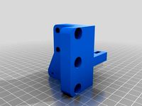
The blower mount attaches to the stock backplate of the carriage via the two lower screws. The stock nylock nuts are removed, the part cooler is put in place, and the screws fasten to the part cooler instead of the nuts. M3 drop-in T-nuts are used inside of the part cooler in order to create a strong attachment to the plastic part that doesn't require the use of a wrench. The nylock nuts have such a small footprint that overtorquing will result in part breakage. The part also features two M3 screw bosses, one each above and below the blower, for installation of screws to push against the backplate in order to finely tune and stabilize the tilt of the air outlet relative to the nozzle. Installation of these screws isn't absolutely necessary... I didn't need them on my latest print of this part, but I may add them to just reduce the amount of flex that the mounting points experience.
I didn't use nuts for fastening screws to the cooler, as I've found that self-threading fine-pitch screws into FDM parts works very well. Holes are sized for a very tight fit, but I recommend reaming M3 threaded holes out to .108" (stabilizing screw bosses), M3 clearance holes out to .120" (part cooler mounting holes), and M4 holes out to .146" (blower mounts). If you don't have those drill sizes, just push HARD and twist screws into the holes to form threads prior to assembly. Take care to support the part well while doing this so you don't break it.
Update: I added a "Reinforced" model with ribs built onto the top of the cooling head because after about 14 hours of printing with my PLA part cooler installed, the right side of the right side of the cooling head has started to sag a bit. Please let me know if the reinforcement ribs prevent this, or if you have any bright ideas to stiffen it without adding too much weight. FYI, I'm running my stock hot end at 210C. In any case, I recommend printing this part in the hottest material you have on hand in order to prevent this. Thanks!
IMPORTANT NOTE: If you use glass or any other top layer on your bed plate, you CANNOT use spring clips (binder clips) to hold it down, especially along the right edge and right half of the rear edge (the FT-5 homes the X axis first). Use low-profile printed clips with ~2mm maximum height off of bed, and manually run the carriage through its limits of travel to check clearance prior to running the printer. As you can see, clearance is very tight, in an effort to get it as close to the part as possible and maximize cooling of the part while minimizing cooling of the heat block (and causing thermal runaway errors).
Required parts:
1x 50x15 24V blower (assumes FT-5 R2 with 24V system)https://www.amazon.com/dp/B0755BY9RH/ref=sxbs_sxwds-stvp_1?pf_rd_m=ATVPDKIKX0DER
(sleeve bearings, but you get 2, and they're cheap)
2x M4 x 20mm screws for attaching blowerhttps://www.amazon.com/M4-0-7-4mm-BUTTON-Stainless-MonsterBolts/dp/B016WN8HUS
2x M3 T-nuts for attaching cooler to carriage
I suggest this kit if you don't have any left over from FT-5 assembly:https://www.amazon.com/2020-Hammer-Fastener-Aluminum-Profile/dp/B077Z94V83
2x M3 x 20-30mm screws for stabilizing/tweaking positionhttps://www.amazon.com/iExcell-Stainless-Button-Socket-Screws/dp/B076H2QJ5C (nice assortment)
Installation:
1) Remove nylock nuts from two lower carriage screws
2) Insert T-nuts (flat side first) into rectangular holes in mounting bosses. I found that using one of the longer M3 screws partially-threaded into the back side of the T-nut works nicely to hang onto the nut while the screw is tightened into it.
3) Tighten carriage screws into T-nuts while hanging onto the screw as suggested above. When threads grab, remove screw from backside of T-nut and finish torquing.
4) Wire up and install blower.
5) Install M3 screws to tweak and stabilize the position of the cooler.
Please let me know how it works out for you! I've included a STEP file for easy re-mixing. Don't you wish everyone would?
Special thanks to Steve Peterson for design feedback and printing expertise! Check out his things... https://www.thingiverse.com/StvPtrsn/about
Similar models
thingiverse
free

Ender-5 Big Cooler by IamSLy
...e slot of the ender-5 shuttle plate. take cheap ones as the quality ones have a thread too wide and will not go through the slot.
thingiverse
free

Adimlab E3D V6 Parts Cooler
...0mm e3d cooler, but adds an adapter to enable the use of a 40mm fan. it is also a remix so it will clear the adimlab x carriage.
thingiverse
free

Creality Hotend Adapter Parts for Tevo Tarantula by zanejohnson97
...a-0-15a-humidifier-aromatherapy-replacement/dp/b071wmhng5/ref=sr_1_5?dchild=1&keywords=5015+fan&qid=1607193820&sr=8-5
thingiverse
free

Vermeer RT950 ROPS Frame Light Mounts by iowajames
...27ttpifszhlfx&dchild=1&keywords=led+flood+light+12v&qid=1606763282&sprefix=led+flood+light%2caps%2c204&sr=8-6
thingiverse
free

Part Cooler for Aluminum X carriage by 3D_LabteK
...ng as the hole is designed to be threaded by the bolt.
the slotted fixing hole allows regulation of the elevation of the blower.
thingiverse
free
40MM Fan & BLTouch Mount for FLSUN Cube by Cmerritt_319
...sults just using the stock z limit switch and the leveling screws.
print quality will improve dramatically once you install this.
thingiverse
free

Flying Bear P902 (Tevo) Titan Mount by MillersMadDesigns
...will need 2 m4 nuts and screws to install it. to mount the shroud to the x mount, you will also need 2 m3 nuts and screws. enjoy!
thingiverse
free

LGA115x CPU Cooler Backplates, M3 Screw (Compatible w/ Hyper 212 Black) by NAnglo
...flathead screws. also, i recommend printing with petg or similar for heat...
thingiverse
free
FT-5 Y Carriage Side Mounts by IOIIOOO
...k better for the m5 and m3 screws, and each now has a flush side so you can print with less support. i also added an idler mount.
thingiverse
free

FT-5 R2 Fang Cooler Endstop Spacer by AngelDMercedes
...right top screw and the nut, pass the screw through the carriage and the printed part and then place the nut back and tighten it.
Creativespark
3d_export
$50

Modular Multilevel Turrets Mechs Robots 3D Model
...tower defense modular multilevel turrets mechs robots 3d model creativespark 89135...
thingiverse
free

Nerf Hyperfire Elite Barrel Extension by CreativeSpark
...it on your gun, and tweak the step file in your cad software (i recommend onshape if you don't have cad software yet). enjoy!
thingiverse
free

2020 to 1/4"-20 Camera Mount by CreativeSpark
...ith a camera that is slightly tilted. i've included the step file for easy remixing, but please give credit if used. enjoy!
thingiverse
free

Glass Hold-Down Clip for FT-5 by CreativeSpark
...esign found here: https://www.thingiverse.com/thing:2834756. included are stl and step files for your remixing pleasure. enjoy!
thingiverse
free

Snap-Together Spool Holder for Folgertech FT-5 R2 by CreativeSpark
...t orientation. i just put it on my ft-5 and it works great! distance between side support "ears" is 3.2" (81mm).
unity_asset_store
$10

Royal Gems
...elevate your workflow with the royal gems asset from creativespark. find this & other props options on the unity...
unity_asset_store
$10

Loot Crates: Military
...your workflow with the loot crates: military asset from creativespark. find this & other props options on the unity...
unity_asset_store
$5

Mechanical Loot Chest
...your workflow with the mechanical loot chest asset from creativespark. find this & other interior options on the unity...
unity_asset_store
$5

Multilevel Turret: Autocannon
...your workflow with the multilevel turret: autocannon asset from creativespark. find this & other weapons options on the unity...
unity_asset_store
$25

RTS Buildings: Humans
...your workflow with the rts buildings: humans asset from creativespark. find this & other sci-fi options on the unity...
Backpack
3d_export
$5

backpack
...pack
3dexport
backpack, all additional bags are separated, all with one texture (there is a map of normals, metallic, roughness)
3d_export
free

Lowpoly backpack
...lowpoly backpack
3dexport
just backpack
turbosquid
$26

Backpack
...urbosquid
royalty free 3d model backpack for download as max on turbosquid: 3d models for games, architecture, videos. (1626981)
turbosquid
$25

Backpack
...urbosquid
royalty free 3d model backpack for download as max on turbosquid: 3d models for games, architecture, videos. (1604398)
turbosquid
$25

Backpack
...urbosquid
royalty free 3d model backpack for download as max on turbosquid: 3d models for games, architecture, videos. (1604390)
turbosquid
$25

backpack
...urbosquid
royalty free 3d model backpack for download as max on turbosquid: 3d models for games, architecture, videos. (1149141)
turbosquid
$7

Backpack
...urbosquid
royalty free 3d model backpack for download as max on turbosquid: 3d models for games, architecture, videos. (1258662)
turbosquid
$10

Backpack
...alty free 3d model backpack for download as max, fbx, and obj on turbosquid: 3d models for games, architecture, videos. (1669421)
turbosquid
$39

Backpack
... free 3d model backpack for download as ma, max, obj, and fbx on turbosquid: 3d models for games, architecture, videos. (1165873)
turbosquid
$35

Backpack
... available on turbo squid, the world's leading provider of digital 3d models for visualization, films, television, and games.
Cooler
archibase_planet
free

Cooler
...hibase planet
wine-cooler wine cooler kitchen equipment
rk wine cooler uc - 3d model (*.gsm+*.3ds) for interior 3d visualization.
archibase_planet
free

Cooler
...cooler
archibase planet
cooler
cooler seyedmms n271212 - 3d model (*.gsm+*.3ds) for interior 3d visualization.
archibase_planet
free
Cooler
...cooler
archibase planet
refrigerator cooler kitchen's technics
cooler - 3d model for interior 3d visualization.
archibase_planet
free
Cooler
...er
archibase planet
pc equipment cooler computer equipment
cooler n040908 - 3d model (*.gsm+*.3ds) for interior 3d visualization.
archibase_planet
free

Cooler
...cooler
archibase planet
cooler cpu fan pc equipment
cooler asus n080211 - 3d model (*.gsm+*.3ds) for interior 3d visualization.
3d_export
$5

Cooler
...cooler
3dexport
water cooler. program maya 2018. materials v-ray 3.6.
3d_export
$5
Juice cooler
...juice cooler
3dexport
juice cooler
turbosquid
$10
Cooler
...uid
royalty free 3d model cooler for download as max and fbx on turbosquid: 3d models for games, architecture, videos. (1478561)
turbosquid
$20
cooler
... available on turbo squid, the world's leading provider of digital 3d models for visualization, films, television, and games.
turbosquid
$20

cooler
... available on turbo squid, the world's leading provider of digital 3d models for visualization, films, television, and games.
Ft
3ddd
free
Renault FT-17
...renault ft-17
3ddd
ft-17 , renault , танк
turbosquid
$85

40 ft container
...id
royalty free 3d model 40 ft container for download as max on turbosquid: 3d models for games, architecture, videos. (1154866)
turbosquid
$45
container 40 ft
...id
royalty free 3d model container 40 ft for download as max on turbosquid: 3d models for games, architecture, videos. (1480343)
turbosquid
$85
Renault FT-17
...yalty free 3d model renault ft-17 for download as 3ds and max on turbosquid: 3d models for games, architecture, videos. (1145251)
turbosquid
$5

NVidia FT 03
... 3d model nvidia ft 03 for download as 3ds, max, obj, and fbx on turbosquid: 3d models for games, architecture, videos. (1233064)
turbosquid
$25

Container 20 ft
...l container 20 ft for download as 3ds, max, obj, fbx, and upk on turbosquid: 3d models for games, architecture, videos. (1384306)
turbosquid
$25
FT Buck Saw
... available on turbo squid, the world's leading provider of digital 3d models for visualization, films, television, and games.
3ddd
free
Jaga - Maxi FT-10
... om
радиатор jaga - maxi ft-10
width: 63 cm
depth: 13 cm
height: 59 cm
сайт производителя:http://www.jaga.be/
turbosquid
$45

20 ft container
...ontainer for download as blend, blend, dae, fbx, obj, and stl on turbosquid: 3d models for games, architecture, videos. (1516815)
turbosquid
$35

Yaesu FT-897D Transceiver
...y free 3d model yaesu ft-897d transceiver for download as max on turbosquid: 3d models for games, architecture, videos. (1160274)
5
turbosquid
$6
Rock 5-5
...urbosquid
royalty free 3d model rock 5-5 for download as obj on turbosquid: 3d models for games, architecture, videos. (1639063)
3d_export
$5
hinge 5
...hinge 5
3dexport
hinge 5
turbosquid
$10
A-5
... available on turbo squid, the world's leading provider of digital 3d models for visualization, films, television, and games.
turbosquid
$2
A-5
... available on turbo squid, the world's leading provider of digital 3d models for visualization, films, television, and games.
turbosquid
$12

Calligraphic Digit 5 Number 5
...hic digit 5 number 5 for download as max, obj, fbx, and blend on turbosquid: 3d models for games, architecture, videos. (1389333)
3ddd
$1

5 роз
...5 роз
3ddd
5 роз в стеклянной вазе
design_connected
$11

iPhone 5
...iphone 5
designconnected
apple iphone 5 computer generated 3d model.
3ddd
$1
Lola 5
...lola 5
3ddd
miniforms
lola 5 miniforms 300*65*134
3ddd
$1

Nexus 5
...dd
nexus , phone , телефон
google nexus 5 phone
3d_ocean
$15

iPhone 5
...iphone 5
3docean
3d 4d apple cinema iphone model modeling phone screen texture
iphone 5 3d model and texture realistic iphone 5.
Part
3d_export
$5
Parts
...parts
3dexport
parts
3d_export
$5
Part
...part
3dexport
part
3d_export
$5

Part
...part
3dexport
machine part
3d_export
$65

Part
...part
3dexport
simple rendering of the scene file
3d_export
$65
Part
...part
3dexport
simple rendering of the scene file
3d_export
$30

fan part
...fan part
3dexport
this is a part of fan of pedastal
3d_export
$10
machine parts
...machine parts
3dexport
3d part modeling work ,contact for 3d work
turbosquid
$59

Mechanical Part
...id
royalty free 3d model mechanical part for download as c4d on turbosquid: 3d models for games, architecture, videos. (1410833)
turbosquid
$17
Road parts
...bosquid
royalty free 3d model road parts for download as 3ds on turbosquid: 3d models for games, architecture, videos. (1192967)
turbosquid
$9

Cutter Parts
...squid
royalty free 3d model cutter parts for download as stl on turbosquid: 3d models for games, architecture, videos. (1220010)