Thingiverse
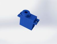
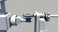
AX2 2 speed gearbox cover + servo mount by Woyta
by Thingiverse
Last crawled date: 3 years ago
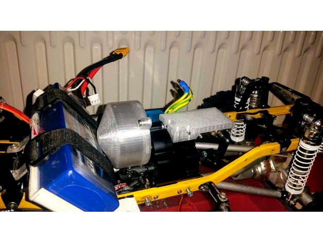
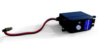
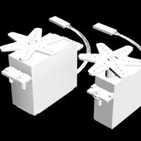
I have bought AX2 2-speed gearbox for my Axial SCX10. I found out that holes of original Axial gerbox cover does not line up with mouting holes on AX2. And mount for 50g servo is to long for my Proline Chevrolet Silverado body. I think that problem will be common for Honcho, Ford F150 or similar bodies. So I designed cover that will fit and servo mount for 9g servo. Servo mount is bigger than it should be but I am using it as a platform for mounting my ESC. Cover itself also could be bit slimmed but I keep it on safe side so there should be no contact between gears and wall.
I have printed it from clear PETG on my Anet A8 with 0,5mm jet.I am still tuning setting for PETG but after little bit it fits nicely under motor mount.
You will need 6x screw M3x8, 3x M3 nut and 2x screw M3x25. These two replace 2x M3x20 that hold motor mount on gearbox and will be short after you put cover base under motor mount. You will probably need them cut to M3x22. But with stock clutch mount it could be OK. I am using solid mount that is closer to gearbox. So I had to cut them to correct lenght.
Update:
-Uploaded version 3. In this version there is bit less space for spur gear but if your spur gear is not sticking out from gearbox to much it should be OK. Reason for this modification is battery mounted in front of transmission. Second modification is more sturdy base with lip. First vesrsion was not sturdy enough and bend a little. That caused gap between booth parts. So new version got thicker edge and booth parts are now overlapping.
Update2:
-Fixed wrong filename AX2-V3-8MM to AX2-V3-10MM. This is version for standart driveshafts.
-Uploaded version 3 for driveshafts with diameter 12mm. My new MS Technology (http://www.mstechnology.cz) does not fit in space given by standart 10mm driveshafts. Actualy distance between stock spur and closest poit on driveshaft is only 1,3mm! Only option is to make wall thin as possible or put hole in there. I were able to position 0,5mm wall in space where it seems that spur or driveshaft does not come in contact with spur or driveshaft. This variant I consider experimental. Seems to be working but your experience could be different.
Similar models
thingiverse
free

Redcat Everest 10 spur gear cover by tallen8
...wn the teeth of the spur gear. so i designed this simple cover. enjoy
ps: there's no mounting holes, i just glued it in place
thingiverse
free

H4 680mm Alien Folding Multicopter - Mounting Plate (Motor Mount) for retractable landing gear servos by Barracdil
...ore/__23483__servoless_retract_with_metal_trunnion_33mm_x_35mm_mount_2pc_.html
depending on printer holes might be a bit tight.
thingiverse
free

Servo Botom by erniepike
...enough room to fit an at tiny 85 or similar chip to make addressable and remove the pwm burden...
thingiverse
free

Gearbox Cover for ZD Racing RAPTORS BX-16 Brushless 4WD Buggy by TheDIYGuy999
...had lots of lockups so far.
it was extremely difficult to design this cover, because there is very little space around the gears.
grabcad
free

Connection Between Motor & Gearbox
...tween motor & gearbox and it covers : flywheel, chapter mechanism interfaces and gears interlock between starter and flywheel
thingiverse
free

Nema 17 Servo Mount for Auto Bed Leveling by Neoburn1035
...stronger and to keep it from wobbling. once i comfortable with the design and it works on my machine i will upload both versions.
thingiverse
free

gearbox cover for xray t2 by patrick2002
...gearbox cover for xray t2 by patrick2002
thingiverse
stones destroyed my gears so i made a gearbox cover
thingiverse
free

Axial Capra Dig Servo Adapter for POWER HD TR-4 Servo by Cromulent_Designs
...fs and shift around on the tiny screws. this adapter has eccentric mounting holes in the correct places to prevent that as well.
thingiverse
free

MOFO Baja Spurless front motor mount and transmission, servo mount, skid, 4x4 trans, 6x6 or 8x8 trans and rear frame brace by MotorforwardRC
...bearings are axial trans output 8x16x5 bearings and 5x14x5 bearings check facebook @mofoxrc mofo rc motor forward rc for help
thingiverse
free

9-18V Motor (RadioShack) Gearbox by NickJallday
...remel tool to smooth our where the motor mounts. i may need to update those sizes for the holes but that worked just fine for me.
Woyta
thingiverse
free

Raspberry Pi Zero + Ethernet / USB hat case (Pihole) by Woyta
...on between pi and hat was tight fit for me. if it is loose you will need piece of double sided tape or change scale of that part.
thingiverse
free

Subaru Outback BP turn signal connector dust cover by Woyta
...so i could mount it with screw. on righ side i had to mount it with zip tie on back side of bracket between headlight and airbox.
thingiverse
free

Air Filter Adapter for BMW vehicles by Woyta
...ribution, non commercial.
// another ebay design and photo thief. robesim0 (italy)
// ebay design thief no.3: 3dprintsnmore (usa)
thingiverse
free

Metal axle with bearings for M416 trailer by Woyta
...le to leaf spring i used m3 threaded rod bent to u shape with help of heat and secured with m3 nuts. or you can just use zip tie.
Ax2
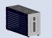
turbosquid
$20

ax2.bmp
... available on turbo squid, the world's leading provider of digital 3d models for visualization, films, television, and games.
thingiverse
free

Karearea Talon Mounts by ChillerFPV
...mounts by chillerfpv thingiverse cutsom 3dprint mounts for lumenier ax2 stubby vtx antenna, immortal t antenne, lipo cable mount+led...
thingiverse
free

Sonicmodell Binary
...fc mount tbs unify pro32 hv mmcx + luminier ax2 micro caddx tarsier mount in the back for the...
thingiverse
free

COFRE DEL TESORO PIRATA by SHAREHORIZONS
...que necesitamos: tablones de madera: (vistos en la imagen) ax2 : 220x152x10 bx2 : 199x98x10 cx2 : 152x98x10 materiales...
cg_trader
$28

Door AX2
...ty gate lock entrance door handle door lock house other close architectural technology office closed open office interior ue4 ue5
grabcad
free

Contactor with additional terminal block
...block grabcad contactor s-t12 вс with additional terminal block ut-ax2 ...
3dwarehouse
free

natami ax2
...natami ax2
3dwarehouse
natami concept all in one keyboard computer, amiga inspired designs. #natami_concept
3dwarehouse
free

Snug AX2 stove
...snug ax2 stove
3dwarehouse
5kw snug woodburner 333 deep 370 wide 475 high #log_stove #snug #stove #wood_burner #woodburner
Gearbox
3d_export
$7

planetary gearbox
...planetary gearbox
3dexport
planetary gearbox
3d_export
$5
transmission gearbox
...transmission gearbox
3dexport
transmission gearbox
3d_export
$30
differential gearbox
...differential gearbox
3dexport
3d model of a differential gearbox.<br>modeled in solidworks.<br>rendered in keyshot.
turbosquid
$4

planetary gearbox
...royalty free 3d model planetary gearbox for download as blend on turbosquid: 3d models for games, architecture, videos. (1423384)
3d_export
$5
three stage planetary gearbox
...three stage planetary gearbox
3dexport
three stage planetary gearbox
turbosquid
$31
2 speed reducer Gearbox
... dual stage helical speed reducer gearbox for download as iam on turbosquid: 3d models for games, architecture, videos. (1650029)
3d_export
$15
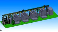
automatic processing line for gearbox pump body
...automatic processing line for gearbox pump body
3dexport
automatic processing line for gearbox pump body
3d_export
$1000

Automobile Manual Transmission mechanism Gearbox 3D Model
...ox 3d model
3dexport
transmission gearbox
automobile manual transmission mechanism gearbox 3d model daveterminator 24996 3dexport
3d_export
$8
tool replacement gearbox
...tool replacement gearbox
3dexport
eccentric lifting mechanism, you can process according to available drawings.
3d_export
$7
milling machine spindle drive diagram - milling gearbox
... n = 4500 rin / min; maximum power p = 7.5 kw. bt40 spindle, like welcome to download to learn. there are igs format files in it.
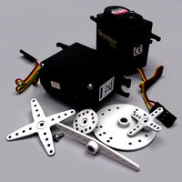
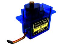
Servo
turbosquid
$30
Servo
...d model servo for download as obj, blend, dae, stl, and sldpr on turbosquid: 3d models for games, architecture, videos. (1394011)
3d_export
$5
servo motor
...tor
3dexport
it's a simple part of servo motor 0.75kw for used in machines assembly to show specified motor in own project.
turbosquid
$1
Servo Moter
...quid
royalty free 3d model servo moter for download as blend on turbosquid: 3d models for games, architecture, videos. (1650816)
turbosquid
free
Motor/Servo
...osquid
royalty free 3d model motor/servo for download as obj on turbosquid: 3d models for games, architecture, videos. (1522522)
turbosquid
$60

Servo Skull
...
royalty free 3d model servo skull for download as ma and fbx on turbosquid: 3d models for games, architecture, videos. (1318573)
3d_export
$5
Servo 3D Model
...rvo 3d model
3dexport
servo
servo 3d model download .c4d .max .obj .fbx .ma .lwo .3ds .3dm .stl pasqualesiciliano 104590 3dexport
turbosquid
$50
Servo Motor
... available on turbo squid, the world's leading provider of digital 3d models for visualization, films, television, and games.
turbosquid
$49
Servo Motor
...model servo motor for download as 3ds, max, obj, fbx, and stl on turbosquid: 3d models for games, architecture, videos. (1324153)
turbosquid
$29
Servo Set
... available on turbo squid, the world's leading provider of digital 3d models for visualization, films, television, and games.
turbosquid
$10
machine servo
... available on turbo squid, the world's leading provider of digital 3d models for visualization, films, television, and games.
Speed
turbosquid
$50

speed
... available on turbo squid, the world's leading provider of digital 3d models for visualization, films, television, and games.
turbosquid
$50

speed
... available on turbo squid, the world's leading provider of digital 3d models for visualization, films, television, and games.
turbosquid
free

speed
... available on turbo squid, the world's leading provider of digital 3d models for visualization, films, television, and games.
3d_ocean
$8
Speed Camera
...model is separate and named appropriately. this is perfect for any type of scene from a road side, architectural or motorway s...
turbosquid
$25

Speed Buggy
...urbosquid
royalty free 3d model speed buggy for download as on turbosquid: 3d models for games, architecture, videos. (1209512)
turbosquid
$4

Speed Sign
...turbosquid
royalty free 3d model speed sign for download as on turbosquid: 3d models for games, architecture, videos. (1251518)
3d_export
$10
variable speed bicycle
...variable speed bicycle
3dexport
variable speed bicycle
3d_export
$5
High - speed aircraft
...high - speed aircraft
3dexport
high speed plane
turbosquid
$5
Speed bag
...y free 3d model speed bag for download as blend, obj, and stl on turbosquid: 3d models for games, architecture, videos. (1577878)
turbosquid
$9

Speed Bump
... 3d model speed bump for download as blend, dae, fbx, and obj on turbosquid: 3d models for games, architecture, videos. (1551854)
Cover
archibase_planet
free

Cover
...cover
archibase planet
cover place setting
cover n170807 - 3d model for interior 3d visualization.
3ddd
$1
cover
...cover
3ddd
ковер , круглый
cover decor
archibase_planet
free

Cover
...cover
archibase planet
cover place setting setting
servis-cafe1930 - 3d model for interior 3d visualization.
turbosquid
free
Coverings
...rings
turbosquid
free 3d model coverings for download as dwg on turbosquid: 3d models for games, architecture, videos. (1279391)
3d_export
$5
plug cover
...plug cover
3dexport
plug cover
turbosquid
$25
Covers
... available on turbo squid, the world's leading provider of digital 3d models for visualization, films, television, and games.
3d_export
$10
manhole cover
...manhole cover
3dexport
manhole cover gost, stl, step
turbosquid
$5
Street Gas Cover Manhole Cover
... available on turbo squid, the world's leading provider of digital 3d models for visualization, films, television, and games.
3ddd
free
Bed cover
...bed cover
3ddd
постельное белье
very useful bed cover
3d_export
$5
cpu cover
...cpu cover
3dexport
cpu cover, cpu box, sheet metal container
Mount
3d_export
free

mounting bracket
...mounting plate is the portion of a hinge that attaches to the wood. mounting plates can be used indoors, cabinetry and furniture.
turbosquid
$2

MOUNTING
... available on turbo squid, the world's leading provider of digital 3d models for visualization, films, television, and games.
turbosquid
free

Mounts
... available on turbo squid, the world's leading provider of digital 3d models for visualization, films, television, and games.
turbosquid
free

Mount Fuji
...fuji
turbosquid
free 3d model mount fuji for download as obj on turbosquid: 3d models for games, architecture, videos. (1579977)
3d_export
$5

Headphone mount LR
...headphone mount lr
3dexport
headphone mount l+r
turbosquid
$39

Mount rainier
...quid
royalty free 3d model mount rainier for download as fbx on turbosquid: 3d models for games, architecture, videos. (1492586)
turbosquid
$5

pipe mounting
...quid
royalty free 3d model pipe mounting for download as obj on turbosquid: 3d models for games, architecture, videos. (1293744)
turbosquid
$3

Mounting Tires
...uid
royalty free 3d model mounting tires for download as fbx on turbosquid: 3d models for games, architecture, videos. (1708511)
3d_export
$5

Magnetic GoPro Mount
...pro mount
3dexport
cool magnetic mount for gopro. allows you to mount the camera on flat metal surfaces and get exclusive shots.
turbosquid
$5

Stone Mount
...ty free 3d model stone mount for download as ma, obj, and fbx on turbosquid: 3d models for games, architecture, videos. (1370306)
2
design_connected
$11
No 2
...no 2
designconnected
sibast no 2 computer generated 3d model. designed by sibast, helge.
turbosquid
$99

Smilodon 2 Pose 2
... available on turbo squid, the world's leading provider of digital 3d models for visualization, films, television, and games.
turbosquid
$20
Barrel Barricade 2-2
... available on turbo squid, the world's leading provider of digital 3d models for visualization, films, television, and games.
turbosquid
$6

Wall Trophy (2) (2)
... available on turbo squid, the world's leading provider of digital 3d models for visualization, films, television, and games.
turbosquid
free
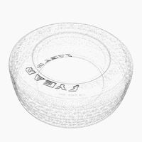
Tire label 2 of 2
... available on turbo squid, the world's leading provider of digital 3d models for visualization, films, television, and games.
3ddd
$1

Кровать, 2 тумбочки, 2 светильника
...кровать, 2 тумбочки, 2 светильника
3ddd
кровать, 2 тумбочки, 2 светильника
нормальное качество
формат 3ds max
без текстур
3ddd
free

Кровать, 2 тумбочки, 2 светильника
...кровать, 2 тумбочки, 2 светильника
3ddd
кровать, 2 тумбочки, 2 светильника
нормальное качество
формат 3ds max
без текстур
turbosquid
$19
Loft wooden square box chandelier (2) (2) (2)
... available on turbo squid, the world's leading provider of digital 3d models for visualization, films, television, and games.
3ddd
$1
ALPEREN-2
...alperen-2
3ddd
комод , alperen-2
комод с зеркалом alperen-2
design_connected
$27

Confluences 2 2-Seater Sofa
... 2-seater sofa
designconnected
ligne roset confluences 2 2-seater sofa computer generated 3d model. designed by nigro, philippe.