Thingiverse

Articulated Arm System by DamianB2
by Thingiverse
Last crawled date: 3 years ago
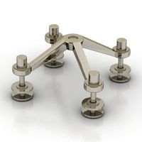
This is a set of files that make up an articulating arm system that can be used to hold probes, PCBs, cameras, or any thing else. The nodes are fully position adjustable and locked with a screw or thumb screw. There are two sizes included (small and large) for different situations. For examples work well with the small system but a camera may require the large system. If needed, the large and small parts can be intermixed using the included adapters. Node shafts fit into holes in the next node, adapter, probe holder, camera mount, etc. The pictures should give you a better idea of how the parts are used.
Printing/Post Processing:
Small nodes with short shaft have been printed successfully at 0.2, 0.16, and 0.12mm layer height with PLA and 30% fill. Print with the shaft facing up and turn off supports.
Large nodes with short shaft have been printed successfully at 0.2mm layer height with PLA and 30% fill. Print with the shaft facing up and turn off supports.
Large nodes with long shaft are a bit more temperamental. As such, I have found the best way to print them is with the shaft facing sideways. The shaft is then needs to be supported. I added a support and it is in the “.stl” itself (so print the file without supports). Both horizontal and vertical “.stl” files are included for the large node with long shaft.
I occasionally had an issue where the portion of the bottom of the ball inside the node would detach during printing. The part was still functional but the missing part needed to be avoided when tightening. If you have this issue, you may want to increase the infill to, say, 60% or try a different infill type.
Probe Holder prints standing upright with holes at the bottom. Print without supports. I used 0.12 layer and 30% fill and no supports.
Gender Changers, Large F to Small M, Large F to Small M, and Alligator Clip Holders print standing upright. I used 0.12 layer and 30% fill…no supports needed.
The Wyze Camera Holder was printed with the platform up (bottom hole facing down). I used 0.12 layer and 30% fill…with supports.
Nodes with “integral supports” should be printed with supports off.
Alligator Clip Holder: Alligator clip holders use a M4 screw to retain the alligator clip.
The large weighted enclosure is assembly using four M4 x 10mm screws.
The large weighted enclosure is assembly using four M3 x 8mm screws.
The large nodes use a M4 x 10mm screw or thumbscrew for shaft locking.
The large nodes use a M3 x 8mm screw or thumbscrew for shaft locking.
I found some screws are slightly undersized. Regular cap screws seem to be truer to their dimensions…thumb screws, and set screws, seem to vary a lot, but are more convenient to adjust.
If the shaft does not hold in well into the adjacent nodes hole, you can always glue it. On PLA you can use a cyanoacrylate glue (superglue).
If you find you need to print the nodes horizontally, you can try the Cura plugin “Custom Supports”. You can use this to place a support under the shaft. (After setting up this support turn off the “support” selection.)
Usage:
Probe Holder: This can be used for oscilloscope probes, DMM probes, etc. Lay probe in the trough and hold in place with rubber bands. (Rubber Bands I used: https://www.amazon.com/gp/product/B083R13FV3/ref=ppx_yo_dt_b_asin_title_o01_s01?ie=UTF8&psc=1 )
Wyze Camera Holder: Attach the Wyze round metal plate and adhesive to the holder top.
Wyze Camera Holder can also serve as a base when flipped over.
The large and small bases should be filled with something to make it heavy enough to support the attached node assemblies. I filed them with some surplus screws I had laying around. You can also use pebbles, sand, scrap metal, etc.
Tips to Making New Adapters
Large node: holes for shaft are 10mm diameter and 6mm deep
Small node: holes for shaft are 7.5mm diameter and 4.5mm deep
The nodes shafts have a slight taper at the far end. On the large nodes, the last 5mm is tapered down at 1.72 degrees. On the small nodes, the last 3.75mm is tapered down at 1.7 degrees. The gender changer shaft has this taper on both ends.
Similar models
thingiverse
free

Mirror Wall Clip by 3DMakerMarket
... aesthetics. i put a one layer thick bridge before the transition to the small hole for ease of printing. no supports required.
thingiverse
free

Wyze Pan Cam Holder by techguychad
...8174v2f?_encoding=utf8&psc=1
i used 6 screw holes in case you get a different bracket to help make it more universal.
enjoy!
thingiverse
free

3D Map of Canada
... will turn out well. these were printed at 0.12 mm layer thickness and 20% fill. no supports required and is an easy print.
enjoy
thingiverse
free

Oscilloscope probe holder by scarou
...s is a 4 parts probe holder "easy to print".
use small screws for assembly or simply glue all parts.
clip on the probe.
thingiverse
free

Bicycle fork hydraulic brake line holder
... 100% infill and printed in under 30 minutes at 0.12 mm layer resolution.
designed in freecad. part file (fcstd format) included.
thingiverse
free

Camera Flash & Umbrella Holder with Tripod thread by MasterFX
... 10mm diameter and can be fixed with a m4 screw.
it should be printed with 0.2mm layer height to get the thread working properly.
thingiverse
free

QIDI X-PLUS WYZE CAMERA CLIP by B0SC0
...t not too long.
it could interfere with the top of the print head
enclosure during printing.
print head temp = 230c
bed temp = 70
thingiverse
free

Shapeoko Touch Probe Holder
... the source for this at onshape
i also ended up creating a mockup for the touch probe itself, so you can also see that at onshape
thingiverse
free

Pegboard Alligator Clip Cable Holder
...n the holes is 1 inch (2.54 cm). the hole diameter is 1/4 of an inch (6.35 mm).
support is not required to print this 3d object.
thingiverse
free

Wyze Wireless Camera Mount by danbaker30
...nstall/remove your wyze wireless camera i made this base that that cam can slide in and out of. print backside down w/o supports.
Damianb2
thingiverse
free

LED Strip Light Cover by DamianB2
...d strip lights. it prints without supports. looks good using white or clear filament. it has 4 holes for mounting using screws
thingiverse
free

LCD Pivoting Enclosure by DamianB2
...1?_encoding=utf8&pd_rd_i=b01dketwo2&pd_rd_r=0tx9me5ec99dd5s8d344&pd_rd_w=p8cyc&pd_rd_wg=wqp9n
but may fit others.
thingiverse
free

CNC Spindle/Laser Storage Holder by DamianB2
... position without any supports. the 2 bin version requires supports turned on.
this was printed on a ender 3 pro in pla at 0.2mm
thingiverse
free

GPS Module Enclosure with Window Mount by DamianB2
...the module blinks the 1pps signal when it gets enough satellites, and being clear would allow you to verify it has a signal lock.
thingiverse
free

Miter Gauge for Bosch RA1181 Router Table by DamianB2
...nob are generic so a miter gauge for many saws and router tables could be made by creating a resized slide to fit the tools slot.
thingiverse
free

Ultrasonic Parking Assist - Arduino Nano by DamianB2
...cted. the ultrasonics will then checks ever second to see if there is forward movement, and re-lights the led strip if there is.
thingiverse
free

Klein Thermal Camera Tripod Mount Enclosure by DamianB2
...etric so you can face the camera in either direction.
some supports are a bit hard to remove but will come out with some digging.
thingiverse
free

GPS Module Enclosure with Window Mount (25x25 mm antenna) by DamianB2
...the module blinks the 1pps signal when it gets enough satellites, and being clear would allow you to verify it has a signal lock.
Articulated
turbosquid
$60

Articulated doll
...e 3d model articulated doll for download as max, obj, and ztl on turbosquid: 3d models for games, architecture, videos. (1277424)
turbosquid
$10
articulated lamp
... available on turbo squid, the world's leading provider of digital 3d models for visualization, films, television, and games.
design_connected
$11
Articulated Industrial Light
...articulated industrial light
designconnected
o. c. white articulated industrial light computer generated 3d model.
cg_studio
$169
Articulated Truck3d model
...cgstudio
.3ds .c4d .lwo .max .obj - articulated truck 3d model, royalty free license available, instant download after purchase.
3d_export
$90
Design Bus Articuled 3D Model
...design bus articuled 3d model
3dexport
design bus articuled
design bus articuled 3d model basshunter 8620 3dexport
turbosquid
$59

Articulated truck 45f
... available on turbo squid, the world's leading provider of digital 3d models for visualization, films, television, and games.
3d_ocean
$130

Caterpillar 725 Articulated Truck
...for close-up renders. scene contain textures, standart scanline, mentalray and vray materials. - high quality polygonal model ...
3d_export
$22

articulated dump truck
...ost popular and not very 3d file formats, as well as textures for shaders.<br>format: 3ds max, obj, fbx, 3ds, lwo, c4d, dae
turbosquid
free

Rigged articulated bus acordion bus for games
...or download as max, max, unitypackage, max, fbx, obj, and 3ds on turbosquid: 3d models for games, architecture, videos. (1599911)
3d_export
$24

dubai bus articulated
...ed check if our models are useful for your project and leave a like if you like this model.<br>thank you for your interest!
Arm
archibase_planet
free
Arm
...ase planet
arm hand right hand skeleton
arm human skeleton right arm n030515 - 3d model (*.gsm+*.3ds+*.max) for 3d visualization.
3ddd
$1

arm chair
...arm chair
3ddd
arm chair , пуф
arm chair
turbosquid
$5
arm
...arm
turbosquid
royalty free 3d model arm for download as obj on turbosquid: 3d models for games, architecture, videos. (1306158)
turbosquid
free

Arm
...arm
turbosquid
free 3d model arm for download as obj and fbx on turbosquid: 3d models for games, architecture, videos. (1346955)
turbosquid
$29
Arm
...osquid
royalty free 3d model arm for download as obj and fbx on turbosquid: 3d models for games, architecture, videos. (1382436)
3d_export
$5

coat of arms
...coat of arms
3dexport
coat of arms
3ddd
$1
ARM SOFA
...arm sofa
3ddd
arm sofa
3ddd
$1
Arm chair
...arm chair
3ddd
arm chair
3ddd
$1
Arm chair
...arm chair
3ddd
угловое
arm chair
3ddd
$1
ARM CHAIR
...arm chair
3ddd
arm chair clothes
System
archibase_planet
free
System
...m
archibase planet
fire alarm system fire alarm box
security light system - 3d model (*.gsm+*.3ds) for interior 3d visualization.
archibase_planet
free
Spider system
...stem spider glass system
spider system to fix glass stefano galli n050912 - 3d model (*.gsm+*.3ds) for interior 3d visualization.
3ddd
$1
Euforia System
...euforia system
3ddd
euforia
euforia system
3d_export
$50
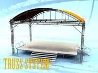
Roof system Truss system 3D Model
...oof system truss system 3d model
3dexport
roof system truss truss stage
roof system truss system 3d model aleksbel 38970 3dexport
3ddd
$1
DVD System
...dvd system
3ddd
dvd , schneider
dvd system
design_connected
free
Seating system
...seating system
designconnected
free 3d model of seating system
3d_export
$5

solar system
...solar system
3dexport
solar system in c4d, with 8k nasa textures
3ddd
$1
Quanta System
...quanta system
3ddd
медицина
quanta system.
лазерное оборудование для медицинских центров
3d_export
$15
solar system
...nd the other the sun, the earth and the moon, the latter has an animation with camera movement included, the files are in spanish
3d_export
$14

missile system
...missile system
3dexport