Thingiverse
Arduino FM Radio with RDA5807 Module by erdayo
by Thingiverse
Last crawled date: 3 years, 3 months ago
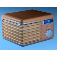
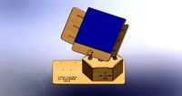
This is an Arduino FM Radio I built by combining 2 different designs. I give all the credit to the two original designers, and I just tweaked the design and .stl files to fit my needs.
If you are looking for a intermediate project for both Arduino and 3D Printing, this can be done in about 2 hours (not counting printing time).
I hate when projects are posted with vague instructions, so I will try to post as much detail as I can. Hit me up if you have any questions for suggestions for improvements.
The first design I used was this one:https://create.arduino.cc/projecthub/indoorgeek/fm-radio-using-arduino-and-rda8057m-73a262?ref=tag&ref_id=radio&offset=11
From this design I took the basic schematic for the radio design itself, the method for mounting the switches, the amplifier circuit, parts of the schematic, and the starting point for the 3D Print files.
I heavily modified the design and did not use the code, so I would just use this as the starting point.
This is the second design I used:https://maker.pro/arduino/projects/simple-fm-radio-receiver-with-arduino-uno-and-rda5807m
I used this design as the main basis of my schematic, including the code in this design, as well as the guide in connecting the RDA5807M, the three button circuit to adjust the station and volume. This specific design does not use a onboard speaker and is designed for a 3.5mmaudio jack. I took this design and added the audio amplifier circuit and speakers from the first design to get a all inclusive FM radio.
The main difference is I used two smaller speakers instead of one big one so I could take advantage of the stereo output of the PAM 8403 Audio Amplifier Module.
I also used tactile switches that did not require printing any additional buttons.
I also used a Arduino Nano as the main circuit, not the Uno.
Here is a list of parts I used. If you use different sized parts (specifically parts that fit in the face plate), you may need to adjust the Radio Face file. If you use the parts I list below, all the holes should fit.
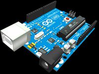
-1x Arduino Nano
3x 10K resistors
-1x RDA5807M FM Radio Tuner IC (https://www.youtube.com/watch?v=4pZmkeqg5h8)
NOTE This chip is ver small and does not come connected to a PC board like typical modules. You will have to take this part and make your own board (see either of the two designs I posted for more specific details or watch this video (https://www.youtube.com/watch?v=4pZmkeqg5h8) and I highly recommend using clipped off leads from an old resistor to wire this chip.
2x 3W Speakers. These come in packs of two (https://www.amazon.com/gp/product/B01LN8ONG4/ref=ppx_yo_dt_b_asin_title_o00_s02?ie=UTF8&psc=1)
-1x I2C OLED Display module 0.91 inch (https://www.amazon.com/gp/product/B08FGVKM91/ref=ppx_yo_dt_b_asin_title_o00_s00?ie=UTF8&psc=1)
-3x Tactile switches (https://www.amazon.com/gp/product/B0897CL27V/ref=ppx_yo_dt_b_asin_title_o08_s00?ie=UTF8&psc=1)
-1x PAM8403 Audio Amplifier (you may want a plastic knob for it if you don't have one. Just search Amazon for Potentiometer Knobs)
(https://www.amazon.com/gp/product/B07TB17NLM/ref=ppx_yo_dt_b_asin_title_o09_s00?ie=UTF8&psc=1)
1 Slide Switch on/off (https://www.amazon.com/gp/product/B08947137H/ref=ox_sc_act_title_2?smid=A32JEPL2VLYM8R&psc=1)
Not Needed but Recommended:
A Really good Hot Glue Gun (I used a Gorilla Glue Gun I got at Walmart)
Female to Female Jumper Wires
-Female to Male Jumper Wires
Male to Male Jumper Wires
Stranded (not solid core) Wire.
I found pre-made jumper wire, especially female to male, made it a lot easier to attach to things like the Amplifier or the OLED boards.
Some good Perf Board (https://www.amazon.com/gp/product/B07ZV8BKNF/ref=ppx_yo_dt_b_asin_title_o00_s02?ie=UTF8&psc=1)
Steps I used to build it:
Assembled the radio on some bread board to test it
Build the circuit using the example in the two designs I posted.
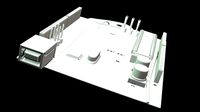
Printed all the files on my printer. Start with the radio face V5
Glued the 2 speakers to the radio face (make sure you glue them on the inside facing out)
Built a separate board just to hold the 3 switches (*using the method in the first design as a guide) You may have to cut your switch circuit board so that it fits between the speakers.
6.To allow switches to be pushed without having them get pushed in the radio, I printed 2 of the the "button face plates". I then hot glued the button face plates to each side of the switch circuit. Then glued them to the back of the face plate. This ensured that the tactile switches protruded enough through the front of the face plate, but were glued to the back of the face plate so they wouldn't get pushed in when pressed.
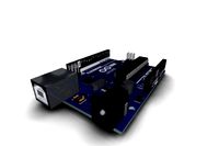
Screwed in the Amplifier though the opening and secured it with the attached screw (you can put the knob on later)
Printed the "OLED No Holes" .stl file. I then CAREfULLY glued the OLED display into the OLED No Holes print. Ensuring that when the display was operational, it was right side up as you looked at the front of the radio (you may want to check which is "Right side up" when you are testing on your perf board). Once the OLED display was correctly glued into the "OLED No Holes", I then glued the OLED No Holes onto the radio face so that the pins for the display were accessible from the back side (you can do this a different way, this way just worked easiest for me)
8.5 Attached your on/off switch through the hole in the radio face plate. You can adjust this based upon what size switch you use, but it's the pre-made rectangular hole)
Connected all the jumper wires where they should go (OLED Display, Amplifier, etc)
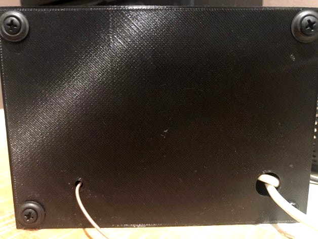
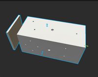
10.Run the USB C cable through the large hole in the back plate, ensuring you put a knot in the cable on the inside so you don't accidently pull out the cable.
Run a piece of wire for the antenna out the small hole in the back plate.
Enjoy your radio.
One problem I did note is that when powering it with a USB and 5v charging brick, if I had the radio volume set to 15, and tried to turn the knob on the power amp all the way up, the radio would cut off and reset (I'm guessing I was trying to push too much power).
When I set the radio volume to 8, I was able to use the full range of control on the amplifier.
This is my first post so feedback is welcome.
Enjoy
If you are looking for a intermediate project for both Arduino and 3D Printing, this can be done in about 2 hours (not counting printing time).
I hate when projects are posted with vague instructions, so I will try to post as much detail as I can. Hit me up if you have any questions for suggestions for improvements.
The first design I used was this one:https://create.arduino.cc/projecthub/indoorgeek/fm-radio-using-arduino-and-rda8057m-73a262?ref=tag&ref_id=radio&offset=11
From this design I took the basic schematic for the radio design itself, the method for mounting the switches, the amplifier circuit, parts of the schematic, and the starting point for the 3D Print files.
I heavily modified the design and did not use the code, so I would just use this as the starting point.
This is the second design I used:https://maker.pro/arduino/projects/simple-fm-radio-receiver-with-arduino-uno-and-rda5807m
I used this design as the main basis of my schematic, including the code in this design, as well as the guide in connecting the RDA5807M, the three button circuit to adjust the station and volume. This specific design does not use a onboard speaker and is designed for a 3.5mmaudio jack. I took this design and added the audio amplifier circuit and speakers from the first design to get a all inclusive FM radio.
The main difference is I used two smaller speakers instead of one big one so I could take advantage of the stereo output of the PAM 8403 Audio Amplifier Module.
I also used tactile switches that did not require printing any additional buttons.
I also used a Arduino Nano as the main circuit, not the Uno.
Here is a list of parts I used. If you use different sized parts (specifically parts that fit in the face plate), you may need to adjust the Radio Face file. If you use the parts I list below, all the holes should fit.
-1x Arduino Nano
3x 10K resistors
-1x RDA5807M FM Radio Tuner IC (https://www.youtube.com/watch?v=4pZmkeqg5h8)
NOTE This chip is ver small and does not come connected to a PC board like typical modules. You will have to take this part and make your own board (see either of the two designs I posted for more specific details or watch this video (https://www.youtube.com/watch?v=4pZmkeqg5h8) and I highly recommend using clipped off leads from an old resistor to wire this chip.
2x 3W Speakers. These come in packs of two (https://www.amazon.com/gp/product/B01LN8ONG4/ref=ppx_yo_dt_b_asin_title_o00_s02?ie=UTF8&psc=1)
-1x I2C OLED Display module 0.91 inch (https://www.amazon.com/gp/product/B08FGVKM91/ref=ppx_yo_dt_b_asin_title_o00_s00?ie=UTF8&psc=1)
-3x Tactile switches (https://www.amazon.com/gp/product/B0897CL27V/ref=ppx_yo_dt_b_asin_title_o08_s00?ie=UTF8&psc=1)
-1x PAM8403 Audio Amplifier (you may want a plastic knob for it if you don't have one. Just search Amazon for Potentiometer Knobs)
(https://www.amazon.com/gp/product/B07TB17NLM/ref=ppx_yo_dt_b_asin_title_o09_s00?ie=UTF8&psc=1)
1 Slide Switch on/off (https://www.amazon.com/gp/product/B08947137H/ref=ox_sc_act_title_2?smid=A32JEPL2VLYM8R&psc=1)
Not Needed but Recommended:
A Really good Hot Glue Gun (I used a Gorilla Glue Gun I got at Walmart)
Female to Female Jumper Wires
-Female to Male Jumper Wires
Male to Male Jumper Wires
Stranded (not solid core) Wire.
I found pre-made jumper wire, especially female to male, made it a lot easier to attach to things like the Amplifier or the OLED boards.
Some good Perf Board (https://www.amazon.com/gp/product/B07ZV8BKNF/ref=ppx_yo_dt_b_asin_title_o00_s02?ie=UTF8&psc=1)
Steps I used to build it:
Assembled the radio on some bread board to test it
Build the circuit using the example in the two designs I posted.
Printed all the files on my printer. Start with the radio face V5
Glued the 2 speakers to the radio face (make sure you glue them on the inside facing out)
Built a separate board just to hold the 3 switches (*using the method in the first design as a guide) You may have to cut your switch circuit board so that it fits between the speakers.
6.To allow switches to be pushed without having them get pushed in the radio, I printed 2 of the the "button face plates". I then hot glued the button face plates to each side of the switch circuit. Then glued them to the back of the face plate. This ensured that the tactile switches protruded enough through the front of the face plate, but were glued to the back of the face plate so they wouldn't get pushed in when pressed.
Screwed in the Amplifier though the opening and secured it with the attached screw (you can put the knob on later)
Printed the "OLED No Holes" .stl file. I then CAREfULLY glued the OLED display into the OLED No Holes print. Ensuring that when the display was operational, it was right side up as you looked at the front of the radio (you may want to check which is "Right side up" when you are testing on your perf board). Once the OLED display was correctly glued into the "OLED No Holes", I then glued the OLED No Holes onto the radio face so that the pins for the display were accessible from the back side (you can do this a different way, this way just worked easiest for me)
8.5 Attached your on/off switch through the hole in the radio face plate. You can adjust this based upon what size switch you use, but it's the pre-made rectangular hole)
Connected all the jumper wires where they should go (OLED Display, Amplifier, etc)
10.Run the USB C cable through the large hole in the back plate, ensuring you put a knot in the cable on the inside so you don't accidently pull out the cable.
Run a piece of wire for the antenna out the small hole in the back plate.
Enjoy your radio.
One problem I did note is that when powering it with a USB and 5v charging brick, if I had the radio volume set to 15, and tried to turn the knob on the power amp all the way up, the radio would cut off and reset (I'm guessing I was trying to push too much power).
When I set the radio volume to 8, I was able to use the full range of control on the amplifier.
This is my first post so feedback is welcome.
Enjoy
Similar models
thingiverse
free
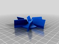
Desk Fan by NebNorse
...lpages04?ie=utf8&psc=1
motor control: https://www.amazon.com/gp/product/b01cnl6imc/ref=od_aui_detailpages04?ie=utf8&psc=1
thingiverse
free

Amp Selector
...title_o06_s01?ie=utf8&psc=1
https://www.amazon.com/gp/product/b07c2nnxkd/ref=ppx_yo_dt_b_asin_title_o07_s00?ie=utf8&psc=1
thingiverse
free

12 Function Deep Dish Button Box by coyoteyz13
..._title_o03_s00?ie=utf8&psc=1
https://www.amazon.com/gp/product/b07vhcb1q4/ref=ppx_yo_dt_b_search_asin_title?ie=utf8&psc=1
thingiverse
free

LED Paracord Dog Collar, Rechargeable by DemonicArchr
...utf8&psc=1
18650 charger board - https://www.amazon.com/gp/product/b01lhd9d7e/ref=oh_aui_detailpage_o02_s00?ie=utf8&psc=1
thingiverse
free

Star Citizen Control Panel 2 by kmobley6030
... to order this twice because i didn't notice that one of the switches in normally closed. you need both to be normally open.
thingiverse
free

Carling OLED Switch
...no.
ds18b20 temperature sensorhttps://smile.amazon.com/gp/product/b013gb27hs/ref=ppx_yo_dt_b_asin_title_o08_s01?ie=utf8&psc=1
thingiverse
free

Guitar Pickup Winder
...=utf8&psc=1
speed adjustmenthttps://www.amazon.com/gp/product/b07vpnhs5j/ref=ppx_yo_dt_b_asin_title_o02_s01?ie=utf8&psc=1
thingiverse
free

Battery/Switch Clip by stugpanzer
...nd a fresh 9volt battery will get you just over an hour and a half. i confirmed that the battery does not get hot while running.
thingiverse
free

FNAF BonBon animatronic puppet by XMASBAD
...title_o04_s02?ie=utf8&psc=1
https://www.amazon.com/gp/product/b06xcrsd3t/ref=ppx_yo_dt_b_asin_title_o01_s00?ie=utf8&psc=1
thingiverse
free

Arduino Powered Video Game Guitar Controller by McDade01
...p screws and nuts (https://www.amazon.com/gp/product/b083sgj7bd/ref=ppx_yo_dt_b_search_asin_title?ie=utf8&psc=1&fpw=alm)


Fm
3ddd
free

FM Bottega
...tega
3ddd
fm bottega , комод
модель комода фабрики fm bottega на заказ art.600 + art.604
3ddd
$1

Кухня FM bottega
...кухня fm bottega
3ddd
fm bottega
классическая кухня fm bottega
3ddd
$1

FM Actual
...ель - fm bottega d'arte. cайт производителя и коллекция -http://www.fmarte.it/page.jsp?idpagina=416
автор - lepan
turbosquid
$8

FM-DK08_Desk
... free 3d model fm-dk08_desk for download as max, obj, and fbx on turbosquid: 3d models for games, architecture, videos. (1252060)
turbosquid
$8

FM-NS08_Nightstand
...3d model fm-ns08_nightstand for download as max, obj, and fbx on turbosquid: 3d models for games, architecture, videos. (1251766)
turbosquid
$3

Table FMS
...lty free 3d model table fms for download as max, fbx, and obj on turbosquid: 3d models for games, architecture, videos. (1661256)
3ddd
$1

Ibanez SA260 fm
...ibanez sa260 fm
3ddd
ibanez , гитара
модель гитара ibanez sa260 fm
turbosquid
$20

fm-njop.lwo
... available on turbo squid, the world's leading provider of digital 3d models for visualization, films, television, and games.
turbosquid
$20

fm-rjop.lwo
... available on turbo squid, the world's leading provider of digital 3d models for visualization, films, television, and games.
design_connected
$18

FM-180 Armchair
...fm-180 armchair
designconnected
fsm fm-180 armchair computer generated 3d model. designed by heiliger, stefan.
Radio
archibase_planet
free
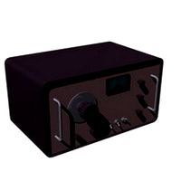
Radio
...radio
archibase planet
radio
radio - 3d model for interior 3d visualization.
archibase_planet
free
Radio
...radio
archibase planet
radio
radio - 3d model for interior 3d visualization.
3d_export
$10
radio
...radio
3dexport
radio 3d, ojb
archibase_planet
free
Radio
...radio
archibase planet
radio set wireless receiver wireless set
radio 2 - 3d model (*.gsm+*.3ds) for interior 3d visualization.
archibase_planet
free
Radio
...radio
archibase planet
radio set wireless receiver wireless set
radio 7 - 3d model (*.gsm+*.3ds) for interior 3d visualization.
archibase_planet
free
Radio
...radio
archibase planet
radio set wireless receiver wireless set
radio 10 - 3d model (*.gsm+*.3ds) for interior 3d visualization.
3d_ocean
$9
Vintage Radio
...vintage radio
3docean
old radio radio set vintage
this is a vintage radio modeled to help in interior design arrangements.
3d_ocean
$8
Radio Branu
...radio branu
3docean
detail radio vintage
vintage radio with detail
3d_export
$5
radio
...radio
3dexport
turbosquid
$25

Radio
...o
turbosquid
royalty free 3d model radio for download as max on turbosquid: 3d models for games, architecture, videos. (1203794)
Arduino
turbosquid
$7
Arduino
...turbosquid
royalty free 3d model arduino for download as max on turbosquid: 3d models for games, architecture, videos. (1197165)
turbosquid
$3
Arduino
...turbosquid
royalty free 3d model arduino for download as c4d on turbosquid: 3d models for games, architecture, videos. (1305484)
3d_export
$5
arduino satellite
...rt
this model is the exact arduino based satellite model with some basic sensors and camera modules and also includes batteries.
turbosquid
$1
Arduino UNO
...alty free 3d model arduino uno for download as , stl, and wrl on turbosquid: 3d models for games, architecture, videos. (1515932)
3d_export
$5
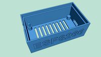
esp8266 box arduino
...esp8266 box arduino
3dexport
box for esp8266 module with wire hole. inside dimensions: 49x26 mm. height 15 mm.
3d_export
$60
Arduino Uno Rev3 Microcontroller 3D Model
...mega328p circuit board spark cable wire 5v 74v 9v 111v
arduino uno rev3 microcontroller 3d model danielgarnier4403 97237 3dexport
3d_export
free
arduino rover kit
...no!!! materials: no!!! rigged: no animated: no uv mapped: no it is not an exact copy of the original! not subject to 3d printing!
3d_ocean
$7
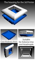
The housing for the 3d Printer
...the housing for the 3d printer 3docean arduino device housing stl the housing consists of two portions:...
3d_export
$5
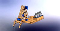
arm 4 axis
...uno -4 servo motor 180° -3 joystick (x,y) for arduino -mdf wood -some wires -cnc laser cut...
3d_export
$5
solar tracker
...machine for the frame . list of material : -arduino uno -2 step motor with driver -4 ldr sensor...
Module
turbosquid
$4

Module
...
turbosquid
royalty free 3d model module for download as max on turbosquid: 3d models for games, architecture, videos. (1259603)
3d_export
free

Martian module
...martian module
3dexport
martian module objects 18 textures are missing
design_connected
$39
Kennedee Moduls
...kennedee moduls
designconnected
kennedee moduls computer generated 3d model. designed by massaud, jean-marie.
design_connected
$39
Sayonara Moduls
...sayonara moduls
designconnected
bbb emmebonacina sayonara moduls computer generated 3d model. designed by decursu, giorgio.
design_connected
$27

Togo Moduls
...togo moduls
designconnected
ligne roset togo moduls computer generated 3d model. designed by ducaroy, michel.
design_connected
$34
Nuvola Moduls
...nuvola moduls
designconnected
bonaldo nuvola moduls 2-seater computer generated 3d model. designed by giuseppe viganò.
3d_export
free
Hibernation module
...hibernation module
3dexport
design_connected
$27
Sabi moduls
...sabi moduls
designconnected
paola lenti sabi moduls 2-seater computer generated 3d model. designed by francesco rota.
3d_export
$50

pls concrete module
...pls concrete module
3dexport
pls concrete module<br>pls with concrete mobile mixer module m5
turbosquid
free
Hibernation module
...squid
free 3d model hibernation module for download as blend on turbosquid: 3d models for games, architecture, videos. (1667696)