GrabCAD
Arduino - chipKIT enclosure, fancy
by GrabCAD
Last crawled date: 1 year, 11 months ago
Note: default "rendering" is an actual picture of 3D printed part in production.
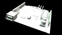
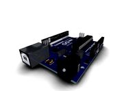
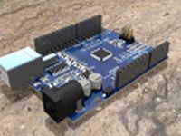
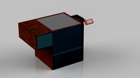
This is the 4th Arduino housing I have designed. The top shield is intended to be the Adafruit 1.8" TFT I have in the library. Below it is an Adafruit prototype shield and a Seeedstudio Mega. Notice the support cage in the middle layer, it is to hold the bottom of the Arduino "stack" up in place. Without it, any inputs to the power connector, USB connector, or other connectors to the other shields could pull them down and away from the top shield.
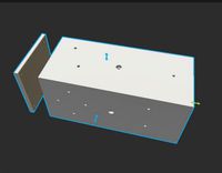
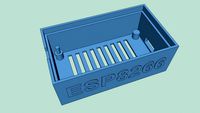
The cutouts in the bottom layer are to add rigidity to the 3D printed model. Without those gothic looking column indents, the 0.125" front wall was very flexible and induced layer adhesion problems during the ABS 3D print. This version is very rigid and did not "split" during the print.
The top shield, the Adafruit 1.8" TFT with joystick and SD card, bolts to the lid with M3 screws. The holes are sized to accept a tap after 3D printing. There are cutouts for the SD card to allow its removal and update as needed when in production. The top lid does bolt into place, but hinges with the 2 pins into the middle layer. This design works well in practical use with the 3D printed ABS.
NOTE: the very top piece, the "lid" has been updated to add more support for the PCB when the screws are tightened. Initial version would allow the PCB to flex, which I found was cause for the TFT to not function properly. Update is its own lone lid_v2.stl file. If you need a different version (STEP, dwg, dxf, etc) please comment and I'll export accordingly. STL loaded because I 3D printed it and tested it.
All bolts besides the top 3 M3 screws are M5 and as 3D printed in ABS are ready to be tapped after the print. My 3D printer shrinks holes slightly, so are sized 0.190" in the drawing. You may need to adjust for your application. Note: I found this hole size would allow the M5 screws to thread into the raw plastic, however, I tested and discovered their strength and "bite" is much more firm if the holes are first tapped!
There is a removable "door" that slides in the middle layer which is trapped by the lid. This door is clumsy in usage, but once the test bench no longer needs updating via the USB connector, will be a more permanent fixture.
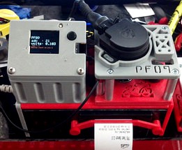
Note about the door and middle layer: the power connector to the Seeedstudio Mega protrudes from the housing. This was my design concession to space restraints. This connector did not lend itself to concealment easily! Also note that the Seeed Mega has an unusual layout. It can be seen and purchased here: http://www.seeedstudio.com/depot/seeeduino-mega-p-717.html I rather like this product for offering Mega performance in an undersized "Uno-like" footprint. (Note: this "Goldilocks" Uno might be even better! http://www.freetronics.com/products/goldilocks-arduino-compatible-with-atmega1284p-mcu )
A write up about this project is here: https://forum.sparkfun.com/viewtopic.php?f=14&t=36254
Update: changed the MCU to chipKIT platform to quadruple my SRAM from 8K to 32K! More here: http://www.chipkit.org/forum/viewtopic.php?f=18&t=2530
This is the 4th Arduino housing I have designed. The top shield is intended to be the Adafruit 1.8" TFT I have in the library. Below it is an Adafruit prototype shield and a Seeedstudio Mega. Notice the support cage in the middle layer, it is to hold the bottom of the Arduino "stack" up in place. Without it, any inputs to the power connector, USB connector, or other connectors to the other shields could pull them down and away from the top shield.
The cutouts in the bottom layer are to add rigidity to the 3D printed model. Without those gothic looking column indents, the 0.125" front wall was very flexible and induced layer adhesion problems during the ABS 3D print. This version is very rigid and did not "split" during the print.
The top shield, the Adafruit 1.8" TFT with joystick and SD card, bolts to the lid with M3 screws. The holes are sized to accept a tap after 3D printing. There are cutouts for the SD card to allow its removal and update as needed when in production. The top lid does bolt into place, but hinges with the 2 pins into the middle layer. This design works well in practical use with the 3D printed ABS.
NOTE: the very top piece, the "lid" has been updated to add more support for the PCB when the screws are tightened. Initial version would allow the PCB to flex, which I found was cause for the TFT to not function properly. Update is its own lone lid_v2.stl file. If you need a different version (STEP, dwg, dxf, etc) please comment and I'll export accordingly. STL loaded because I 3D printed it and tested it.
All bolts besides the top 3 M3 screws are M5 and as 3D printed in ABS are ready to be tapped after the print. My 3D printer shrinks holes slightly, so are sized 0.190" in the drawing. You may need to adjust for your application. Note: I found this hole size would allow the M5 screws to thread into the raw plastic, however, I tested and discovered their strength and "bite" is much more firm if the holes are first tapped!
There is a removable "door" that slides in the middle layer which is trapped by the lid. This door is clumsy in usage, but once the test bench no longer needs updating via the USB connector, will be a more permanent fixture.
Note about the door and middle layer: the power connector to the Seeedstudio Mega protrudes from the housing. This was my design concession to space restraints. This connector did not lend itself to concealment easily! Also note that the Seeed Mega has an unusual layout. It can be seen and purchased here: http://www.seeedstudio.com/depot/seeeduino-mega-p-717.html I rather like this product for offering Mega performance in an undersized "Uno-like" footprint. (Note: this "Goldilocks" Uno might be even better! http://www.freetronics.com/products/goldilocks-arduino-compatible-with-atmega1284p-mcu )
A write up about this project is here: https://forum.sparkfun.com/viewtopic.php?f=14&t=36254
Update: changed the MCU to chipKIT platform to quadruple my SRAM from 8K to 32K! More here: http://www.chipkit.org/forum/viewtopic.php?f=18&t=2530
Similar models
thingiverse
free

1.8" TFT Shield Cover Plate by MakerDan55
...ard slot and reset button. now with integrated reset button.
update: i have added a new stl for the newer version of this shield.
thingiverse
free

Arduino Mega 2560, shield and 3.2" TFT with SD Card reader case by joostan
...erse
while creating a diy pixelstick equiv i needed a case for my arduino mega, sainsmart shield and 3.2" tft touchscreen.
cg_trader
$3

7 tft bezel Arduino mega | 3D
...7 tft bezel arduino mega | 3d
cg trader
3d model of 7" tft screen, with arduino mega plus shield.
thingiverse
free

Arduino Due and Mega + shield enclosure by PaulH
...he infill, at least on the first layer, which means the print will not work. i used cura to slice this item which then prints ok.
thingiverse
free

Arduino MEGA +1.8'' TFT Case by elik745i
...ft case by elik745i
thingiverse
this is arduino mega case with 1.8'' tft lcdfor debugging. this is for my ihome project.
grabcad
free

Adafruit 1.8" TFT Arduino Graphics Shield
...for this graphics shield. i also use this shield with my "food box" project here: http://grabcad.com/library/food-box-1
grabcad
free

2.4" TFT Display Shield
...2.4" tft display shield
grabcad
this is a model of a popular 2.4" display shield for use with arduino uno/mega.
thingiverse
free

Case for Arduino Mega with Sainsmart 3.2 TFT
.... i didn't put any holes for screws as i didn't need them. the fusion 360 files are included if anyone needs to add them.
grabcad
free

TFT Mega Touch LCD Shield
...tft mega touch lcd shield
grabcad
for use with arduino mega
thingiverse
free

Arduino Uno Snug Case by Esquilo
...ino mega snug case.
for the raspberry pi, see my raspberry pi snug case.
update 11/20/15: added hole on top for the reset button.
Chipkit
thingiverse
free

ChipKit Max32 Playboard by avfusion
... and fill worked fine for me.
chipkit max32 by microchip/digilenttransparent breadboard by evilmadscientisttiny breadboard by ems
thingiverse
free

Shield Separator for Arduino / chipKIT by logansam
...
sick of your shields getting stuck on your boards? use this to pry between the board and the shield to avoid bending the pins.
thingiverse
free

Digilent uC32 Chipkit and Breadboard Holder by _MF
...er is fixed in the included stl
holds a uc32 arduino compatible microcontroller and a standard breadboard for easy prototyping!
thingiverse
free

LCD keypad shield arduino maple chipkit case by macsboost
...n powercell for charging.
the arduinos used in this build are the olimex 328, the olimex leonardo or arduino leonardo or similar.
thingiverse
free

WF32 Board Holder by amrrll
...pcb. designed with holes for mounting and corner supports. wf32:https://www.digilentinc.com/products/detail.cfm?navpath=2,892,1193&prod=chipkitwf32 ...
thingiverse
free

Turntable for David 4 & 5 & HP 3DScan & more by janbbeck
...setups. at the heart of the turntable are a chipkit uno32, an adafruit motor shield and a nema17 step...
thingiverse
free

Spareparts: 3d models of various random electronic and mechanical components for OpenSCAD by sadr0b0t
...0, 0]) ir_line_sensor(); arduino boards and shields use <spareparts/arduino.scad> chipkituno32(); translate([100, 0, 0]) arduino_uno(); translate([200, 0, 0]) arduino_uno_china(); translate([300,...
grabcad
free

Chipkit Max32 dimensional mockup
...chipkit max32 dimensional mockup
grabcad
dimensional mockup of the digilent chipkit max32
grabcad
free

Digilent ChipKit WF32 Fast Draft
...digilent chipkit wf32 fast draft
grabcad
digilent chipkit wf32
fast draft
pic32 power + built in wifi
Fancy
3d_ocean
$3

Fancy Glass
...fancy glass
3docean
day fancy friends glass good happy
fancy glass for your best day… have a nice day
3d_export
$35

Fancy smurf
...fancy smurf
3dexport
fancy smurf poligon : 25.217 vertices : 25.318 extentions : - zbrush - obj - stl stl properties : 10*25*12
turbosquid
$12

Fancy Painting
...quid
royalty free 3d model fancy painting for download as ma on turbosquid: 3d models for games, architecture, videos. (1562259)
design_connected
$11

Fancy Chic
...ected
photo-realistic 3d models of the fancy chic table from ligne roset for 3d architectural and interior design presentations.
turbosquid
$26

Fancy Breslate
...alty free 3d model fancy breslate for download as 3dm and stl on turbosquid: 3d models for games, architecture, videos. (1596881)
turbosquid
$15

Fancy Commode
...yalty free 3d model fancy commode for download as max and obj on turbosquid: 3d models for games, architecture, videos. (1362922)
turbosquid
$15

Fancy Wardrobe
...alty free 3d model fancy wardrobe for download as max and obj on turbosquid: 3d models for games, architecture, videos. (1362949)
3d_export
$5

Fancy Chair
...fancy chair
3dexport
support me!
turbosquid
$25

Fancy Sofa
...ty free 3d model fancy sofa for download as max, obj, and fbx on turbosquid: 3d models for games, architecture, videos. (1203353)
turbosquid
$20

Fancy Chair
...free 3d model fancy chair for download as blend, obj, and fbx on turbosquid: 3d models for games, architecture, videos. (1660304)
Arduino
turbosquid
$7
Arduino
...turbosquid
royalty free 3d model arduino for download as max on turbosquid: 3d models for games, architecture, videos. (1197165)
turbosquid
$3
Arduino
...turbosquid
royalty free 3d model arduino for download as c4d on turbosquid: 3d models for games, architecture, videos. (1305484)
3d_export
$5
arduino satellite
...rt
this model is the exact arduino based satellite model with some basic sensors and camera modules and also includes batteries.
turbosquid
$1
Arduino UNO
...alty free 3d model arduino uno for download as , stl, and wrl on turbosquid: 3d models for games, architecture, videos. (1515932)
3d_export
$5
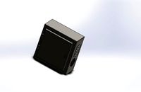
esp8266 box arduino
...esp8266 box arduino
3dexport
box for esp8266 module with wire hole. inside dimensions: 49x26 mm. height 15 mm.
3d_export
$60
Arduino Uno Rev3 Microcontroller 3D Model
...mega328p circuit board spark cable wire 5v 74v 9v 111v
arduino uno rev3 microcontroller 3d model danielgarnier4403 97237 3dexport
3d_export
free
arduino rover kit
...no!!! materials: no!!! rigged: no animated: no uv mapped: no it is not an exact copy of the original! not subject to 3d printing!
3d_ocean
$7
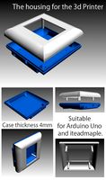
The housing for the 3d Printer
...the housing for the 3d printer 3docean arduino device housing stl the housing consists of two portions:...
3d_export
$5
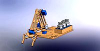
arm 4 axis
...uno -4 servo motor 180° -3 joystick (x,y) for arduino -mdf wood -some wires -cnc laser cut...
3d_export
$5

solar tracker
...machine for the frame . list of material : -arduino uno -2 step motor with driver -4 ldr sensor...
Enclosure
3d_export
free
electrical enclosure
...l enclosure where electrical devices like (relays, contactors, busbars ) are kept in order to protect from hazardous environment.
turbosquid
$100
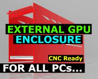
GPU Enclosure
...yalty free 3d model gpu enclosure for download as obj and stl on turbosquid: 3d models for games, architecture, videos. (1381061)
3d_export
$5
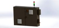
Electrical Enclosure
...ed. also has tower lights attaced on the top.<br>file format that are available:<br>.step<br>.obj<br>.stl
archive3d
free
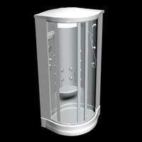
Enclosure 3D Model
...closure 3d model
archive3d
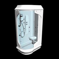
shower enclosure-acquarius- 3d model for interior 3d visualization.
archive3d
free
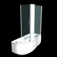
Enclosure 3D Model
...enclosure 3d model
archive3d
shower enclosure-omega- 3d model for interior 3d visualization.
archive3d
free
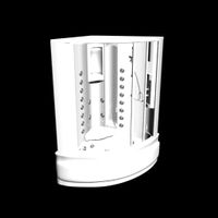
Enclosure 3D Model
...enclosure 3d model
archive3d
shower enclosure-vega - 3d model for interior 3d visualization.
archive3d
free
Enclosure 3D Model
...enclosure 3d model
archive3d
shower enclosure-zenith - 3d model for interior 3d visualization.
turbosquid
$20
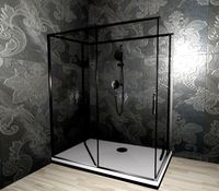
shower enclosure
... available on turbo squid, the world's leading provider of digital 3d models for visualization, films, television, and games.
turbosquid
$14
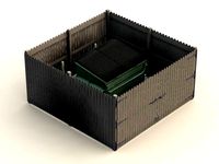
Dumpster Enclosure
... available on turbo squid, the world's leading provider of digital 3d models for visualization, films, television, and games.
turbosquid
$25
3d printer enclosure
... model 3d printer enclosure for download as ipt, skp, and fbx on turbosquid: 3d models for games, architecture, videos. (1634310)