Thingiverse
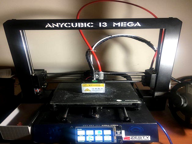
Anycubic I3 Mega Zesty Nimble/SKR1.3/E3D V6 Conversion
by Thingiverse
Last crawled date: 4 years, 2 months ago
Hey guys!
This is pretty much my biggest upload.
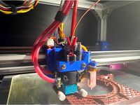
In this post, I will be doing my best to detail how I managed to upgrade the Anycubic I3 Mega to include The Zesty Nimble (a remote direct drive extruder), the E3D V6 all-metal hot-end, two 4010 blower fans, the 32 bit SKR1.3, 5 TMC 2208 Stepper Drivers, and the TFT 35 V2.0 Touchscreen.
The benefits are amazing:
The printer is relatively silent
Print speeds are drastically faster and more precise
More marlin features can be enabled, giving more control over the printer with no chance of stalling or overworking the processor
More control is given over SD printing with a higher functioning touch screen
Z-height is improved with a smaller carriage
Rigidity is improved with a shorter hotend
Cooling is greatly enhanced, making overhangs easier/safer
Flexible filament printing is easily accomplished
Purchased Items:
SKR 1.3 Mainboard
TFT35 V2.0
5 TMC 2208 V3.0 Stepper Drivers
E3D V6 hotend (direct drive package)
Zesty Nimble (95cm cable)
Winsinn 4010 Blower Fans with Air Guides
Assorted test leads (for extending wires)
Heat shrink
Wire Strippers
Assorted M3 nut and bolt set (varying lengths)
Drill
Stepper bit (through 11/16" dia)
3mm drill bit
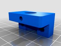
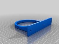
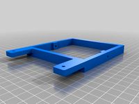
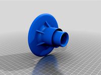
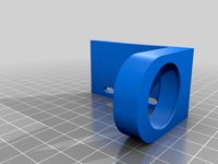
Printed Items:
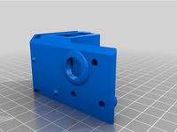
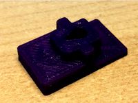
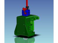
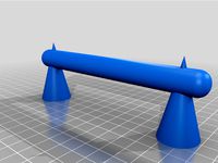
V6 to Nimble Adapter
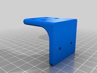
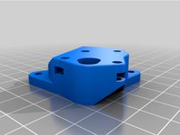
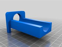
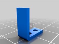
Extruder Adapter
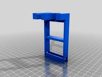
Trigorilla to SKR Adapter
So, I pretty much did this build for my own printing abilities with the potential side goal of making this an actual Thing here, so some information may be hard to follow.
Reference all photos to make sure you properly understand what's been accomplished, and if you can't make sense, DM me or post a comment.
Steps:
Make sure you have all the purchased items.
Print all printed items in as high a temperature plastic as you can
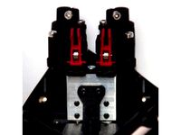
Mount the SKR board on the Trigorilla to SKR Adapter using 4 screws and nuts
Assemble the motor, spindle, and drive cable to the Extruder Adapter
Place TMC2208 drivers into the SKR board, making sure of the orientation and ensuring jumper placement to enable UART
Change board voltage jumper to 5v and flash the firmware from downloads, then change the jumper back (Note: You will need atom to do this. Google search/youtube how to flash
-------This completes the basic setup of the electronics and major new components...
Remove the existing hot end, hotend metal shroud, temp sensor, and fan, noting all connections
Using the stepper and drill, drill the mounting hole for the old stepper until the hole is 11/16" dia
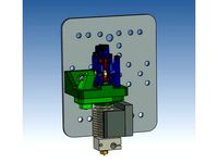
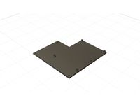
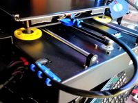
Mockup the mount of the nimble drive on the top plate of the carriage as in the photos and drill two holes through the nimble bolt holes and through the metal plate so that the two match
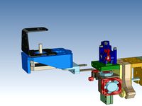
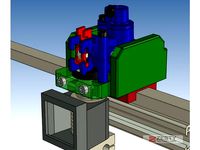
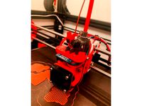
Assemble the E3D v6 (see E3D for proper assy) and mount it to the carriage using supplied nimble hardware and the V6 to Nimble Adapter. (Note: make sure to test fit before tightening, and ensure even tightening to prevent damage or inducing angle in the hotend alignment) Feed all wires through grating and strip/ heat shrink wires as needed from photos
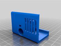
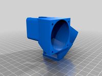
Take a 4010 blower, put an air guide on it and place it on the inside of the metal hotend shroud and align it to roughly where it would blow air at the nozzle tip when mounted
Using the drill and 3mm bit, gently park the bottom two holes of the fan, then drill the housing out and "wobble" the drill bit up and down to make an ovular slot allowing for adjustment later, if needed.
Once repeated for the left and right sides of the shroud, go ahead and mount the fans using the 3mm bolts.
Cut and strip the leads coming off both fans, twist them together, and then twist and heat-shrink them to the leads of the stock fan connector. (Note: You'll need to cut and strip the stock fan connector's leads as well)
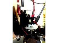
Go ahead and install the flex drive of the nimble to the extruder motor and the top of the nimble direct-drive and secure using the supplied hardware
-----This completes all of the mechanical setup necessary to get the machine running. TFT35 will come later on.
Carefully turn the machine on its side and remove the bottom cover.
Remove the trigorilla board and MAKE NOTE OF EVERY CONNECTION (Note: The wiring of the I3 Mega uses a lot of similarly colored wires and a few misc shared bundles)
Using the photographs to the best of your abilities (also commenting uncertainties to me), transfer all trigorilla wires to the new board. Some wires will need extending and at least one harness cable will need to be partially jumpered, but this is a working setup. Please disregard all bltouch wiring. (NOTE: I made a mistake when installing my main power connections and got the polarity reversed, so red will be black and black will be red for you, but the board is reverse polarity protected, so no major worries)
Making sure of all connections, route the main power from the PSU to the board and power up the machine.
Using the supplied USB cable, connect to the printer and check temperatures and end-stops (m119 while holding down the end stops). Make all necessary adjustments or corrections and consider gluing the leads in place so that they don't wiggle out over time.
Once verified as working, disconnect from the printer, turn off the power supply, and gently place the board to the side
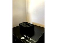
Remove the stock LCD touchscreen by unbolting it and peeling it out of its housing
Attach the data cable supplied to the TFT35 and connect the other end to the board after running the wire through the opening in the front of the printer where the old screen used to be
Mount the screen temporarily with adhesive, or in my case, by aligning it over the old opening and using the drill and 3mm bit to make two holes in the metal case for long hardware to be used to clamp it down
Ensure the connection is proper and not reversed by powering up the unit and waiting for it to connect. (Note: This usually takes a few seconds, and if the connection is reversed, the screen won't turn on)
Bolt the plate back on to the bottom of the printer and flip it back over
Fully calibrate the printer... PID tune the bed, reset the gantry height using the screws on the Z-axis, relevel the bed with the four corners, and double-check all connections and hardware locations.
Print and test, consider using Cura and my supplied profile.
Consider liking and commenting for the effort and making a Paypal donation to offset costs and figuring everything out.
paypal.me/jbrow532
I genuinely hope this helps transform this platform for you all and that it at least inspires those who are maybe unsure of their machine to question what makes it work and what more it could do!
Thanks, everybody! Enjoy!
This is pretty much my biggest upload.
In this post, I will be doing my best to detail how I managed to upgrade the Anycubic I3 Mega to include The Zesty Nimble (a remote direct drive extruder), the E3D V6 all-metal hot-end, two 4010 blower fans, the 32 bit SKR1.3, 5 TMC 2208 Stepper Drivers, and the TFT 35 V2.0 Touchscreen.
The benefits are amazing:
The printer is relatively silent
Print speeds are drastically faster and more precise
More marlin features can be enabled, giving more control over the printer with no chance of stalling or overworking the processor
More control is given over SD printing with a higher functioning touch screen
Z-height is improved with a smaller carriage
Rigidity is improved with a shorter hotend
Cooling is greatly enhanced, making overhangs easier/safer
Flexible filament printing is easily accomplished
Purchased Items:
SKR 1.3 Mainboard
TFT35 V2.0
5 TMC 2208 V3.0 Stepper Drivers
E3D V6 hotend (direct drive package)
Zesty Nimble (95cm cable)
Winsinn 4010 Blower Fans with Air Guides
Assorted test leads (for extending wires)
Heat shrink
Wire Strippers
Assorted M3 nut and bolt set (varying lengths)
Drill
Stepper bit (through 11/16" dia)
3mm drill bit
Printed Items:
V6 to Nimble Adapter
Extruder Adapter
Trigorilla to SKR Adapter
So, I pretty much did this build for my own printing abilities with the potential side goal of making this an actual Thing here, so some information may be hard to follow.
Reference all photos to make sure you properly understand what's been accomplished, and if you can't make sense, DM me or post a comment.
Steps:
Make sure you have all the purchased items.
Print all printed items in as high a temperature plastic as you can
Mount the SKR board on the Trigorilla to SKR Adapter using 4 screws and nuts
Assemble the motor, spindle, and drive cable to the Extruder Adapter
Place TMC2208 drivers into the SKR board, making sure of the orientation and ensuring jumper placement to enable UART
Change board voltage jumper to 5v and flash the firmware from downloads, then change the jumper back (Note: You will need atom to do this. Google search/youtube how to flash
-------This completes the basic setup of the electronics and major new components...
Remove the existing hot end, hotend metal shroud, temp sensor, and fan, noting all connections
Using the stepper and drill, drill the mounting hole for the old stepper until the hole is 11/16" dia
Mockup the mount of the nimble drive on the top plate of the carriage as in the photos and drill two holes through the nimble bolt holes and through the metal plate so that the two match
Assemble the E3D v6 (see E3D for proper assy) and mount it to the carriage using supplied nimble hardware and the V6 to Nimble Adapter. (Note: make sure to test fit before tightening, and ensure even tightening to prevent damage or inducing angle in the hotend alignment) Feed all wires through grating and strip/ heat shrink wires as needed from photos
Take a 4010 blower, put an air guide on it and place it on the inside of the metal hotend shroud and align it to roughly where it would blow air at the nozzle tip when mounted
Using the drill and 3mm bit, gently park the bottom two holes of the fan, then drill the housing out and "wobble" the drill bit up and down to make an ovular slot allowing for adjustment later, if needed.
Once repeated for the left and right sides of the shroud, go ahead and mount the fans using the 3mm bolts.
Cut and strip the leads coming off both fans, twist them together, and then twist and heat-shrink them to the leads of the stock fan connector. (Note: You'll need to cut and strip the stock fan connector's leads as well)
Go ahead and install the flex drive of the nimble to the extruder motor and the top of the nimble direct-drive and secure using the supplied hardware
-----This completes all of the mechanical setup necessary to get the machine running. TFT35 will come later on.
Carefully turn the machine on its side and remove the bottom cover.
Remove the trigorilla board and MAKE NOTE OF EVERY CONNECTION (Note: The wiring of the I3 Mega uses a lot of similarly colored wires and a few misc shared bundles)
Using the photographs to the best of your abilities (also commenting uncertainties to me), transfer all trigorilla wires to the new board. Some wires will need extending and at least one harness cable will need to be partially jumpered, but this is a working setup. Please disregard all bltouch wiring. (NOTE: I made a mistake when installing my main power connections and got the polarity reversed, so red will be black and black will be red for you, but the board is reverse polarity protected, so no major worries)
Making sure of all connections, route the main power from the PSU to the board and power up the machine.
Using the supplied USB cable, connect to the printer and check temperatures and end-stops (m119 while holding down the end stops). Make all necessary adjustments or corrections and consider gluing the leads in place so that they don't wiggle out over time.
Once verified as working, disconnect from the printer, turn off the power supply, and gently place the board to the side
Remove the stock LCD touchscreen by unbolting it and peeling it out of its housing
Attach the data cable supplied to the TFT35 and connect the other end to the board after running the wire through the opening in the front of the printer where the old screen used to be
Mount the screen temporarily with adhesive, or in my case, by aligning it over the old opening and using the drill and 3mm bit to make two holes in the metal case for long hardware to be used to clamp it down
Ensure the connection is proper and not reversed by powering up the unit and waiting for it to connect. (Note: This usually takes a few seconds, and if the connection is reversed, the screen won't turn on)
Bolt the plate back on to the bottom of the printer and flip it back over
Fully calibrate the printer... PID tune the bed, reset the gantry height using the screws on the Z-axis, relevel the bed with the four corners, and double-check all connections and hardware locations.
Print and test, consider using Cura and my supplied profile.
Consider liking and commenting for the effort and making a Paypal donation to offset costs and figuring everything out.
paypal.me/jbrow532
I genuinely hope this helps transform this platform for you all and that it at least inspires those who are maybe unsure of their machine to question what makes it work and what more it could do!
Thanks, everybody! Enjoy!
Similar models
thingiverse
free

Zesty Nimble and E3D v6 hotend mount for RailCore II 3D printer
...imble and e3d v6 hotend mount for the railcore ii 3d printer. it has guides for the nimble drive cable and teflon filament tube.
thingiverse
free
Ultimaker 2 - Zesty Nimble V2 & E3D V6 upgrade by MacNite
...is an additional slide-on cover to "hide" the stepper motor assembly away and make everything look tidy.
not tested yet
thingiverse
free
Nimble V1 Tevo Black Widow Quick Release clamp for E3D V6 by ZestyTech
...uder you can buy, it has ample torque and can be mounted in multiple orientations.
the nimble is available from zesty technology.
thingiverse
free
E3D V6 Dual 40mm Fan Adapter by OmniDevil
...e3d v6 dual 40mm fan adapter by omnidevil
thingiverse
a mount to upgrade the stock e3d v6 hotend fan to a dual fan.
thingiverse
free
Anycubic i3 mega skr 1.4 board mount adapter by Kris_3D_Druck
...rd mount adapter by kris_3d_druck
thingiverse
this is a adapter to mount the skr 1.4 board where the trigorilla board should be.
thingiverse
free
Nimble V1 and Nimble V2 on the E3D Toolchanger
...uder you can buy, it has ample torque and can be mounted in multiple orientations.
the nimble is available from zesty technology.
thingiverse
free
Adaper to mount a Nimble V1 on MGN-12 slider by ZestyTech
...uder you can buy, it has ample torque and can be mounted in multiple orientations.
the nimble is available from zesty technology.
thingiverse
free

IR Probe Mount for E3D V6 Shroud by rs4race
...
ir probehttps://miscsolutions.wordpress.com/mini-height-sensor-board/
e3d v6http://e3d-online.com/e3d-v6/full-kit/v6-3mm-direct
thingiverse
free
V-Core Pro Carriage for Zesty Nimble v2 and e3d threaded v6 heatsink by oliof
... mount for ratrigs v-core pro kit for using a zesty nimble v2. it uses the threaded e3dv6 heatsink because i dislike groovemount.
thingiverse
free
E3D V6 Direct to Bowden adapter by sb43201
...43201
thingiverse
this adapter allows to mount compression fitting on the top to convert a e3d v6 direct hotend to bowden drive.
Zesty
3d_sky
free
ZESTY CHAIR by PLY COLLECTION
...zesty chair by ply collection
3dsky
http://www.plycollection.com/eng/chairs/zesty/
thingiverse
free

Zesty Nimble Mount for Tevo Tarantula
...esty nimble mount for tevo tarantula
thingiverse
this is my zesty nimble mount for the tevo tarantula which i used in our video.
thingiverse
free
Zesty Nimble Gimbal 3030
...zesty nimble gimbal 3030
thingiverse
remix for extrusion 3030
thingiverse
free
Gimble for Zesty Nimble on RailCoreII by Atalon
...coreii by atalon
thingiverse
i remixed this zesty nimble extruder motor gimble mount to fit kraeger's railcoreii 3d printer.
thingiverse
free
Zesty Nimble Mini Base by profdryoman
... zesty nimble.
see pictures for more info.
matches 3 mm outer / 2 mm inner ptfe.
second stl matches 4 mm outer / 2 mm inner ptfe.
thingiverse
free

Zesty Sidewinder stepper bracket mount 90 degrees
...ees bracket for mounting the stepper bracket for the zesty sidewinder on the original stepper mount on printers like the ender 3.
thingiverse
free
Hypercube Mount for Zesty Nimble v2 and Orion Piezo
...ion for the zesty nimble v2 and the orion piezo.
all other needed parts are from here https://www.thingiverse.com/thing:2617424.
thingiverse
free
Railcore Zesty Nimble Motor Mount
...lon locking nuts to hold it together. that is your choice. supports will help the holes to turn out better, but are not required.
thingiverse
free
Zesty Nimble and E3D v6 hotend mount for RailCore II 3D printer
...imble and e3d v6 hotend mount for the railcore ii 3d printer. it has guides for the nimble drive cable and teflon filament tube.
thingiverse
free
Zesty Adapter for Blue Eagle Labs Metal Delta by thystonius
...s are valid. also i highly recommend double checking your steps_per_mm. please do let me know if you find some better settings.
Nimble
turbosquid
$25
Nimble Chair
... available on turbo squid, the world's leading provider of digital 3d models for visualization, films, television, and games.
3d_export
$10

toyota i-tril
...residents of small and medium-sized cities. a small and nimble three-seater electric car with a range of more than...
3d_export
$99

titanfall stryder
...survive a straight-up slugfest.<br>the stryder is an agile and nimble ***an, favouring speed and mobility over the other ***ans,...
3d_export
$25

Cartoon Zooba Nix Rigged Ready For Games
...'balanced'. on the character menu, she is described as “nimble and cunning”. nix is a very crafty fox that...
thingiverse
free
Nimble Inside by ZestyTech
...uder you can buy, it has ample torque and can be mounted in multiple orientations.
the nimble is available from zesty technology.
thingiverse
free
Nimble V1 and Nimble V2 on the E3D Toolchanger
...uder you can buy, it has ample torque and can be mounted in multiple orientations.
the nimble is available from zesty technology.
thingiverse
free
Mockup of the Dual Nimble aka Nimble C/C by ZestyTech
...uder you can buy, it has ample torque and can be mounted in multiple orientations.
the nimble is available from zesty technology.
thingiverse
free
Nimble V2 mount for Tevo TLM
...uder you can buy, it has ample torque and can be mounted in multiple orientations.
the nimble is available from zesty technology.
thingiverse
free
HevoRT Nimble V2 + Kryo mount
...hevort nimble v2 + kryo mount
thingiverse
this is a remix of miragec caridge to accommodate the nimble v2 and kryo
thingiverse
free
Nimble V2 mount for the BLV Cube
...uder you can buy, it has ample torque and can be mounted in multiple orientations.
the nimble is available from zesty technology.
Anycubic
thingiverse
free
anycubic filament holder
...anycubic filament holder
thingiverse
anycubic filament holder
thingiverse
free
Cableholder Anycubic Mega
...cableholder anycubic mega
thingiverse
cableholder anycubic mega
thingiverse
free
AnyCubic Toolholder by WildManPrinting
...anycubic toolholder by wildmanprinting
thingiverse
anycubic i3 mega toolholder that clips on the side of the spool a-frame.
thingiverse
free
AnyCubic Funnel by phana007
...anycubic funnel by phana007
thingiverse
funnel for anycubic resin and also a reducer for a normal soda bottle.
thingiverse
free
Anycubic Kossel PID calibration
...ir mount:
kossel raspberry camera ir mount
extruder pid calibration.
simple extruder temperature calibration of your 3d printer.
thingiverse
free
anycubic mega i3
...anycubic mega i3
thingiverse
anycubic i3 mega/mega s led 30mm 10-14v 6500k
thingiverse
free
Handle for anycubic by cruiser7
...handle for anycubic by cruiser7
thingiverse
its easier to handle the cover of the anycubic mono x and wash&care
thingiverse
free
anycubic predator Printbed by Lihyon
...anycubic predator printbed by lihyon
thingiverse
anycubic predator printbed
thingiverse
free
Anycubic Predator Triggers by marcelcountry
...anycubic predator triggers by marcelcountry
thingiverse
anycubic predator triggers
thingiverse
free
support anycubic cable by sarpdental
...support anycubic cable by sarpdental
thingiverse
support anycubic cable
Mega
3ddd
$1
BoConcept / Mega
...boconcept / mega
3ddd
boconcept
boconcept mega
3ddd
free

Angelo - Mega shoin
... mega shoin , shoin
angelo - mega shoin - 3dmax 2008
3ddd
$1
Комод MEGA
...вана по фото с учетом реальных размеров.
стек не сколапсен, есть возможность регулировки уровня сглаживания.
текстуры в архиве.
3ddd
$1
Hulsta / Mega-design
...hulsta / mega-design
3ddd
hulsta
hulsta mega-design
design_connected
$18
Tolomeo Mega
...
photo-realistic 3d models of the tolomeo mega floor lamps from artemide for 3d architectural and interior design presentations.
turbosquid
$119

Mega Soldier
... free 3d model mega soldier for download as obj, c4d, and fbx on turbosquid: 3d models for games, architecture, videos. (1148568)
turbosquid
$100
Mega Yacht
... free 3d model mega yacht for download as obj, fbx, and blend on turbosquid: 3d models for games, architecture, videos. (1368903)
3ddd
$1

Massproductions Mega
... massproductions , mega
ширина: 180 см
глубина: 90 см
высота: 79 см
3d_export
$4
mega metro station
...mega metro station
3dexport
mega metro station. ready to game. thanks all downloaders!!
3ddd
$1
BAS Mega
...bas mega
3ddd
bas , ванна
ванна
E3D
turbosquid
$23

E3D - Google Home
... 3d model e3d - google home for download as max, obj, and c4d on turbosquid: 3d models for games, architecture, videos. (1192509)
cg_studio
free

e3d model
...e3d model
cgstudio
- e 3d model, royalty free license available, instant download after purchase.
turbosquid
$2
Syringe C4D (E3D Ready)
...lty free 3d model syringe c4d (e3d ready) for download as c4d on turbosquid: 3d models for games, architecture, videos. (1336720)
turbosquid
$12
Microphone USB E3D and C4D
...ree 3d model microphone usb e3d & c4d for download as c4d on turbosquid: 3d models for games, architecture, videos. (1568216)
turbosquid
$29

E3D - OnePlus 6 Black
...model e3d - oneplus 6 black for download as max, obj, and c4d on turbosquid: 3d models for games, architecture, videos. (1358534)
turbosquid
$29

E3D - Motorola One 2018
...del e3d - motorola one 2018 for download as max, obj, and c4d on turbosquid: 3d models for games, architecture, videos. (1358533)
turbosquid
$29
E3D - Disney MagicBands 2
...l e3d - disney magicbands 2 for download as max, obj, and c4d on turbosquid: 3d models for games, architecture, videos. (1355515)
turbosquid
$29

E3D - Samsung Z4 Smartphone
...e3d - samsung z4 smartphone for download as max, obj, and c4d on turbosquid: 3d models for games, architecture, videos. (1182179)
turbosquid
$23

E3D - Razer Phone model
...del e3d - razer phone model for download as max, obj, and c4d on turbosquid: 3d models for games, architecture, videos. (1231207)
turbosquid
$23

E3D - Alcatel Idol 5
... model e3d - alcatel idol 5 for download as max, obj, and c4d on turbosquid: 3d models for games, architecture, videos. (1212799)
V6
3d_export
$100
v6 engine
...engine
3dexport
complete v6 engine modeled on solidworks 2017 along with .stl, .sldprt and .sldasm of all th parts and assembly.
3d_export
$10
V6 engine
... the first v6 engines were designed and produced independently by marmon motor car company, deutz gasmotoren fabrik and delahaye.
3d_export
$35
v6 engine
...s a complete model of a v6 engine containing over 400 components. you can contact me for a video of all the components assembling
3d_export
$10

v6 engine
...v6 engine
3dexport
turbosquid
$25

Bed1001-v6
... available on turbo squid, the world's leading provider of digital 3d models for visualization, films, television, and games.
turbosquid
$22
Chair2-v6
... available on turbo squid, the world's leading provider of digital 3d models for visualization, films, television, and games.
turbosquid
$20

V6.mb
... available on turbo squid, the world's leading provider of digital 3d models for visualization, films, television, and games.
3d_export
$20
V6 engine
...rovided in this package is all the parts in sldprt format and assembly in sldasm format. i can also convert the format on demand.
3ddd
$1
Стол V6
...6" в стиле дизельпанк изготовлен из блока двигателя, 4х поршней и 4х шатунов.
столешница изготовлена из стекла толщиной 8мм.
cg_studio
$199
V6 VVTi3d model
...v6 vvti3d model
cgstudio
.3ds - v6 vvti 3d model, royalty free license available, instant download after purchase.
Conversion
3ddd
$1
Conversation Seat
...шетка
the conversation seat made in englandhttp://www.squintlimited.com/products/the_conversation_seat/gold
+ max 2011
3d_export
$10
Converse 3D Model
...converse 3d model
3dexport
converse shoe pc unix mac
converse 3d model electropainter17075 38067 3dexport
turbosquid
$100

converse-shoe
...quid
royalty free 3d model converse-shoe for download as c4d on turbosquid: 3d models for games, architecture, videos. (1398427)
turbosquid
$10

Conversation Furniture
... available on turbo squid, the world's leading provider of digital 3d models for visualization, films, television, and games.
turbosquid
$7
Converse Allstars
... available on turbo squid, the world's leading provider of digital 3d models for visualization, films, television, and games.
design_connected
$16
Conversation Club Chair
...conversation club chair
designconnected
donghia conversation club chair chairs computer generated 3d model. designed by n/a.
design_connected
$27

Hemicycle Conversation Chair
...rsation chair
designconnected
ligne roset hemicycle conversation chair computer generated 3d model. designed by nigro, philippe.
3d_export
$24

Converse keds 3D Model
...converse keds 3d model
3dexport
converse all star ked shoe clothes sports
converse keds 3d model vermi1ion 26201 3dexport
3ddd
$1
Converse All-Star Shoes
...converse all-star shoes
3ddd
кеды , обувь
converse all-star shoes
design_connected
$18

CONVERSE Jack Purcell Sneakers
...converse jack purcell sneakers
designconnected
converse jack purcell sneakers computer generated 3d model.
I3
3d_export
$10
suv i3
...suv i3
3dexport
suv i3 2013 series
3d_ocean
$89

BMW i3 2012
...y, in real units of measurement, qualitatively and maximally close to the original. model formats: - *.max (3ds max 2008 scanl...
cg_studio
$99

BMW i3 20143d model
...
cgstudio
.3ds .c4d .fbx .lwo .max .obj - bmw i3 2014 3d model, royalty free license available, instant download after purchase.
cg_studio
$99

BMW i3 20123d model
...tudio
.3ds .c4d .fbx .lwo .max .mb .obj - bmw i3 2012 3d model, royalty free license available, instant download after purchase.
cg_studio
$99

BMW i3 20143d model
...tudio
.3ds .c4d .fbx .lwo .max .mb .obj - bmw i3 2014 3d model, royalty free license available, instant download after purchase.
humster3d
$75

3D model of BMW i3 2014
...
buy a detailed 3d model of bmw i3 2014 in various file formats. all our 3d models were created maximally close to the original.
humster3d
$40

3D model of Kitchen Set I3
...uy a detailed 3d model of kitchen set i3 in various file formats. all our 3d models were created maximally close to the original.
3d_ocean
$30
Kitchen set i3
...ensils oven plates shelves sink table ware
kitchen set i3 include 3d models: cooker, oven, sink, cupboards, table, chair, plates.
3d_ocean
$89

BMW i3 2014
...y, in real units of measurement, qualitatively and maximally close to the original. model formats: - *.max (3ds max 2008 scanl...
cg_studio
$99

BMW i3 Concept 20113d model
...i3
.3ds .c4d .fbx .lwo .max .obj - bmw i3 concept 2011 3d model, royalty free license available, instant download after purchase.
3
turbosquid
$10
Mountain Bike 3 -3 of 3
...model mountain bike 3 (#3 of 3) for download as fbx and blend on turbosquid: 3d models for games, architecture, videos. (1438752)
turbosquid
$6

Rock 3-3
...urbosquid
royalty free 3d model rock 3-3 for download as obj on turbosquid: 3d models for games, architecture, videos. (1628065)
turbosquid
$29
Books 150 pieces 3-3-3
...books 150 pieces 3-3-3 for download as max, obj, fbx, and stl on turbosquid: 3d models for games, architecture, videos. (1384033)
turbosquid
$3

Genesis 3 Clothing 3
... available on turbo squid, the world's leading provider of digital 3d models for visualization, films, television, and games.
3d_export
$5
hinge 3
...hinge 3
3dexport
hinge 3
3ddd
$1
Розетка 3
...розетка 3
3ddd
розетка
розетка 3
turbosquid
$50
is-3
... available on turbo squid, the world's leading provider of digital 3d models for visualization, films, television, and games.
turbosquid
$10
Mountain Bike 3 -2 of 3
...model mountain bike 3 (#2 of 3) for download as fbx and blend on turbosquid: 3d models for games, architecture, videos. (1438750)
turbosquid
$10
Mountain Bike 1 -3 of 3
...model mountain bike 1 (#3 of 3) for download as fbx and blend on turbosquid: 3d models for games, architecture, videos. (1438743)
3d_export
$5

3 CATS
...3 cats
3dexport
3 cats pen holder