Thingiverse
Anycubic I3 Mega Y Dual Extruder conversion by 3D_Rapid_de
by Thingiverse
Last crawled date: 3 years ago
!! WICHTIGE ÄNDERUNG !!
Ich habe den MOD von Marlin 1.1.8 auf 1.1.5 downgegraded!
Mit der 1.1.8 sowie der 1.1.x bugfix(Stand März.2018) ist es trotz bugfix zum "reverse planner bug" gekommen bzw. sind die "bleeding edges" probleme immer noch vorhanden.
Die 1.1.5 läuft sowohl mit Linear Advance sowie ohne diesen bug mit original TFT support!
(TFT support config thx to Christian Hopp)
Sollte jemand einen andern release candidate haben wollen, möchte er sich bei mir melden. Ich habe von 1.1.0 bis 1.1.x bugfix alle umgearbeitet.
Download Linkhttps://github.com/Blackcombify/anycubic-i3-mega-marlin1.1.5-2in1-nozzle-branch-by-blackcombify-maxgrundler
!! IMPORTANT CHANGE !!
I've downgraded the MOD from Marlin 1.1.8 to 1.1.5!
the 1.1.8 and the 1.1.x bugfix (March 2018) it has come despite bugfix to the "reverse planner bug" or the "bleeding edges" problems are still present.
The 1.1.5 runs both with Linear Advance and without this bug & original TFT support! (TFT support config thx to Christian Hopp)
If someone wants to have another release candidate, feel free to contact me. I have reworked from 1.1.0 to 1.1.x bugfix all candidates with tft support.
Download Linkhttps://github.com/Blackcombify/anycubic-i3-mega-marlin1.1.5-2in1-nozzle-branch-by-blackcombify-maxgrundler
feel free to tip!
https://www.youtube.com/watch?v=9PdE_59pAQM
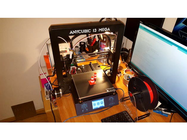
Mit dieser Mod Firmware, welche auf Marlin basiert könnt ihr euren Anycubic I3 Mega auf Dual Extrusion via Y Verteiler mit nur einem Hotend umbauen.
Die Firmware ist nur mit der ersten i3 Version V1 und der zweiten V1.1 Ultrabase kompatibel! Die V1.4 wird nicht supported! Die 1.4 befindet sich auch nicht in meinem Besitz, somit kein Support.
!! Vorweg möchte ich noch sagen, ich übernehme keine Haftung/Verantwortung oder ähnliches.
Jeder ist für die Modifizierung seines Druckers selbst verantwortlich.
Wenn ihr von vornherein wisst, das ihr 2 Linke Hände habt, dann überlegt es euch 2 mal. Ich kann und werde nur begrenzt Support geben.
Meiner Meinung nach sollten folgende Grundvoraussetzungen vorhanden sein:
elektrisches Grund Know-how
Vorkenntnisse in Marlin
Sketch kompilieren/uploaden sollte bekannt sein
Eigeniniative! (gängige Suchmaschinen helfen:))
Hinweis!: Durch diese Firmware verliert die Ultrabase Version den linken Endschalter! dies lässt sich leider nicht vermeiden, da die 2 Z-Stepper Motoren danach parallel laufen und nur noch 1 Endschalter geschalten werden kann. (jeder Standard DIY Printer läuft mit nur einem Z-Endschalter ;))
Es wird benötigt:
1x Nema17 Stepper 1,8Grad 1,5A
1x Extrudersatz
1x Ø1,75 Bowden Tube ca. 500 mm
3x PC4-M6 pneumatische Schnellverbinder
Prinzipiell empfehle ich die Firmware individuell anzupassen! Die aktuelle ist nach meinen persönlichen Vorstellungen gestaltet.
Infos zum .hex File bzw. zu meiner generellen Anpassung:
Das Heatbed wird nicht mehr per BangBang gesteuert/geheitzt, sondern über PID! (die BedLED blinkt dadurch)
Der Autotune wird über M303 E-1 C10 S60 gestartet ( C=10 Intervalle, S60Grad)
gesetzt wird dann durch M304 Pxx Ixx Dxx und mit M500 speichern.
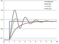
Linear Advance ist aktiviert, steht aber auf K0 R0 (falls gewünscht, Infos auf google)
Ich habe die Pins von Port Z2 auf E1 umbelegt um den zweiten Extruder benutzten zu können.
Der Z-Dual Stepperbetrieb wurde deaktiviert (ist notwendig)
Der Z-Dual Endstopbetrieb wurde deaktiviert (ist notwendig)
Steps/Acceleration sowie Jerk wurden an die originalen Werte angepasst.
Die Steps des E2 Extruders müssen auch eingestellt werden! (aktuell sind meine Werte hinterlegt).
Der Steps des zweiten Extruders können über M92 T1 E92.6 gesetzt werden. Mit M500 abspeichern.
Dies sind die gröbsten Änderungen.
Zum technischen Teil,
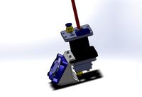
der zweite Z-Stepper der original auf E1 steckt, wird an den freien Z2 gesteckt. Der neue Stepper(Extruder2) wird an den E1 Port gesteckt (siehe Pinout Bilder).
Ich habe das Kabel durch die Schalteröffnung vorne Links geführt.
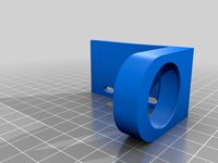
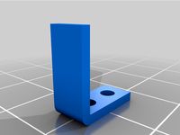
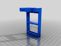
Den Extruder habe ich wie auf den Bildern links befestigt.
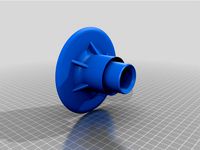
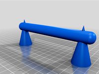
Nun druckt euch das Y-Stück liegend aus und schraubt 3x PC4-M6 Pneymatikschnellverbinder ein. In das V5 Hotend wird nun 1 Stück Teflonschlauch geschoben, welches unten bündig am Heatbreak ansteht. Oben sollte es soweit herausschauen dass das Y Stück mit samt Verbinder etwas Luft zwischen beiden Verbindern bildet. Die Schnellverbinder werden beide mit Kabelbinder gesichert (wie der Original Verbinder am Hotend)
Beide Extruder via Bowden Tube mit dem Y-Stück verbinden.
Für den Slicer kann ich euch nur mit Simplify3D helfen.
Die Problematik ist nun, Simplify braucht für einen Filamentwechsel bei dieser Länge
(Retract 150mm) ein Toolchange-Script.
Das Skript ist in Textform hinterlegt. Bis zur Funktion hat mich das gut 1,5 Tage gekostet ;)
Das Startscript muss auch eingefügt werden!
Diese Methode hat leider einen kleinen Haken, Simplify muss immer mit T0 starten. Dadurch müsst ihr natürlich je nach Teil die richtige Farbe im richtigen Extruder haben.
Die Skripte sind so ausgelegt, dass die Länge von Nozzle bis zum obersten Schnellverbinder um die 160 mm beträgt. Solltet ihr länger sein, müsst ihr das anpassen!
Ihr müsst außerdem ein neues Profil mit Dual Extruder anlegen. Ein Farb-Tower (Grundierungsstütze) mit ca 15mm muss eingestellt werden.
Wenn also alles erledigt ist, dann sieht der Ablauf wie folgt aus:
1 Extruder aufheizen!
2 T0 Material bis zum Schnellverbinder einfahren
3 T1 Material bis zum Schnellverbinder einfahren
4 Programm starten
5 Start Skript fährt T1 in die Noozle und wieder zurück.
6 Start Skript fährt T0 in die Noozle und bleibt.
7 T0 beginnt den Druck!
Nun sollte bei jedem Farbwechsel das Filament zurückgefahren werden und das neue auf dem Farb-Tower eingedruckt.
Also wer bis hier gelesen hat, der wird merken, ohne etwas Knowhow bzw. Liebe zum Hobby ist das ganze nicht zu empfehlen.
Wie schon gesagt, für mich ist es nicht möglich jedem immer und überall zu helfen.
Aber um das Prinzip verstanden zu haben, reicht es allemal :)
Auf die Arduino/Marlin Geschichte gehe ich nicht ein, diese Anforderung ist Grundvorassetzung. Wer da ohne wissen editiert, riskiert die Funktion seines Druckers.
Ich werde demnächst das Hotend komplett tauschen, um den Werkzeugwechsel Retract zu minimieren! Infos dazu folgen.
Für wen es hilfreich war, der darf gerne mal nen "TIP" (Spende) geben.
AAAAAAAAAAAAAAAAAAAAAAAAAAAAAAAAAAAAAAAAAAAAAAAAAAAAAAAAAAAA
for now english google translator :) correct translation will follow
with this mod firmware, which is based on Marlin, you can convert your Anycubic I3 Mega to an Y Dual Extrusion with only one Hotend.
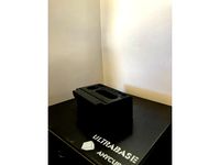
The firmware is only compatible with the first i3 version V1 and the second V1.1 Ultrabase! The V1.4 is not supported!
!! I would like to say in advance, I assume no liability / responsibility or similar.
Everyone is responsible for modifying their printer themselves.
If you know you have left hands, then think twice. I can and will only give limited support.
In my opinion, the following basic conditions should be present:
electrical reason know-how
previous knowledge in Marlin
compile / upload sketch should be known
own initiative! (common search engines help :))
Note !: With this firmware, the ultrabase version loses the left endstop! Unfortunately, this can not be avoided, because the 2 Z stepper motors run parallel. (every standard DIY Printer runs with only one Z endstop ;))
It is required:
1x Nema17 Stepper 1,8degrees 1,5A
1x extruder set
1x Ø1.75 Bowden tube approx. 500 mm
3x PC4-M6 pneumatic quick connectors
In principle, I recommend customizing the firmware! The current is designed according to my personal ideas.
Information about the .hex file or about my general adaptation:
The heatbed is no longer controlled by BangBang no with PID! (the BedLED will flash)
The autotune is started via M303 E-1 C10 S60 (C = 10 intervals, S60degrees)
set it by M304 Pxx Ixx Dxx and save with M500.
Linear Advance is activated, but is on K0 R0 (if you want, info on google)
I changed the pins from port Z2 to E1 to use the second extruder.
The Z-Dual stepper mode has been deactivated (is necessary)
The Z-dual endstop operation has been deactivated (is necessary)
steps / acceleration and Jerk have been adjusted to the original values.
The steps of the E2 extruder must also be set! (currently my values are deposited).
The steps of the second extruder can be set via M92 T1 E92.6. Save with M500.
These are the changes.
To the technical part,
the second Z-Stepper, which is originally on E1, is put on the free Z2. The new stepper (extruder2) is plugged into the E1 port (see pinout pictures).
I pulled the cable through the switch opening on the front left.
I attached the extruder as shown in the pictures on the left.
Now print the Y-piece reclining and screw in 3x PC4-M6 pneumatic-connector. Put in a piece of bowden tube In the V5 hotend , which is below flush with the heatbreak. Above it should look out so far that the Y piece together with connector forms some air between the two connectors. The quick connectors are both secured with cable ties (like the original connector on the Hotend)
Connect both extruders to the Y-piece via bowden tube.
For the Slicer I can only help you with Simplify3D.
The problem is now, Simplify needs for a filament change at this length
(Retract 150mm) a toolchange script.
The script is in text form. I spent 1,5 days for this arrrrgh ;)
The start script must also be inserted!
Simplify always has to start with T0. Of course you have to put in the right color in the right extruder depending on the part.
The scripts are designed so that the length from Nozzle to the top quick connector is around 160 mm. If yours should be longer, you have to adjust that in the script!
You also need to create a new profile with dual extruders. A color tower (grounding support) with about 15mm must be set.
So if everything is done, then the process looks like this:
1 heat up extruder!
2 put in material up to the quick connector for T0
3 put in material up to the quick connector for T1
4 start the program
5 start script moves T1 to Noozle and back.
6 start script moves T0 into the Noozle and stays.
7 T0 starts printing!
Now, with each color change, the filament should be retracted and the new one printed on the color tower.
So who has read up to here, will remember, without some know-how or love for the hobby, the whole thing is impossible.
As I said before, for me it is not possible to help anyone anytime, anywhere.
but hope helps for understanding:)
I will not explain the Arduino / Marlin story, this requirement is a basic requirement. Those who edit without knowing risk the function of their printer.
I will replace the hotend completely in the near future to minimize the tool change retract! informations follow, stay prepared
For whom it was helpful, maybe do a "TIP" (donation).
Ich habe den MOD von Marlin 1.1.8 auf 1.1.5 downgegraded!
Mit der 1.1.8 sowie der 1.1.x bugfix(Stand März.2018) ist es trotz bugfix zum "reverse planner bug" gekommen bzw. sind die "bleeding edges" probleme immer noch vorhanden.
Die 1.1.5 läuft sowohl mit Linear Advance sowie ohne diesen bug mit original TFT support!
(TFT support config thx to Christian Hopp)
Sollte jemand einen andern release candidate haben wollen, möchte er sich bei mir melden. Ich habe von 1.1.0 bis 1.1.x bugfix alle umgearbeitet.
Download Linkhttps://github.com/Blackcombify/anycubic-i3-mega-marlin1.1.5-2in1-nozzle-branch-by-blackcombify-maxgrundler
!! IMPORTANT CHANGE !!
I've downgraded the MOD from Marlin 1.1.8 to 1.1.5!
the 1.1.8 and the 1.1.x bugfix (March 2018) it has come despite bugfix to the "reverse planner bug" or the "bleeding edges" problems are still present.
The 1.1.5 runs both with Linear Advance and without this bug & original TFT support! (TFT support config thx to Christian Hopp)
If someone wants to have another release candidate, feel free to contact me. I have reworked from 1.1.0 to 1.1.x bugfix all candidates with tft support.
Download Linkhttps://github.com/Blackcombify/anycubic-i3-mega-marlin1.1.5-2in1-nozzle-branch-by-blackcombify-maxgrundler
feel free to tip!
https://www.youtube.com/watch?v=9PdE_59pAQM
Mit dieser Mod Firmware, welche auf Marlin basiert könnt ihr euren Anycubic I3 Mega auf Dual Extrusion via Y Verteiler mit nur einem Hotend umbauen.
Die Firmware ist nur mit der ersten i3 Version V1 und der zweiten V1.1 Ultrabase kompatibel! Die V1.4 wird nicht supported! Die 1.4 befindet sich auch nicht in meinem Besitz, somit kein Support.
!! Vorweg möchte ich noch sagen, ich übernehme keine Haftung/Verantwortung oder ähnliches.
Jeder ist für die Modifizierung seines Druckers selbst verantwortlich.
Wenn ihr von vornherein wisst, das ihr 2 Linke Hände habt, dann überlegt es euch 2 mal. Ich kann und werde nur begrenzt Support geben.
Meiner Meinung nach sollten folgende Grundvoraussetzungen vorhanden sein:
elektrisches Grund Know-how
Vorkenntnisse in Marlin
Sketch kompilieren/uploaden sollte bekannt sein
Eigeniniative! (gängige Suchmaschinen helfen:))
Hinweis!: Durch diese Firmware verliert die Ultrabase Version den linken Endschalter! dies lässt sich leider nicht vermeiden, da die 2 Z-Stepper Motoren danach parallel laufen und nur noch 1 Endschalter geschalten werden kann. (jeder Standard DIY Printer läuft mit nur einem Z-Endschalter ;))
Es wird benötigt:
1x Nema17 Stepper 1,8Grad 1,5A
1x Extrudersatz
1x Ø1,75 Bowden Tube ca. 500 mm
3x PC4-M6 pneumatische Schnellverbinder
Prinzipiell empfehle ich die Firmware individuell anzupassen! Die aktuelle ist nach meinen persönlichen Vorstellungen gestaltet.
Infos zum .hex File bzw. zu meiner generellen Anpassung:
Das Heatbed wird nicht mehr per BangBang gesteuert/geheitzt, sondern über PID! (die BedLED blinkt dadurch)
Der Autotune wird über M303 E-1 C10 S60 gestartet ( C=10 Intervalle, S60Grad)
gesetzt wird dann durch M304 Pxx Ixx Dxx und mit M500 speichern.
Linear Advance ist aktiviert, steht aber auf K0 R0 (falls gewünscht, Infos auf google)
Ich habe die Pins von Port Z2 auf E1 umbelegt um den zweiten Extruder benutzten zu können.
Der Z-Dual Stepperbetrieb wurde deaktiviert (ist notwendig)
Der Z-Dual Endstopbetrieb wurde deaktiviert (ist notwendig)
Steps/Acceleration sowie Jerk wurden an die originalen Werte angepasst.
Die Steps des E2 Extruders müssen auch eingestellt werden! (aktuell sind meine Werte hinterlegt).
Der Steps des zweiten Extruders können über M92 T1 E92.6 gesetzt werden. Mit M500 abspeichern.
Dies sind die gröbsten Änderungen.
Zum technischen Teil,
der zweite Z-Stepper der original auf E1 steckt, wird an den freien Z2 gesteckt. Der neue Stepper(Extruder2) wird an den E1 Port gesteckt (siehe Pinout Bilder).
Ich habe das Kabel durch die Schalteröffnung vorne Links geführt.
Den Extruder habe ich wie auf den Bildern links befestigt.
Nun druckt euch das Y-Stück liegend aus und schraubt 3x PC4-M6 Pneymatikschnellverbinder ein. In das V5 Hotend wird nun 1 Stück Teflonschlauch geschoben, welches unten bündig am Heatbreak ansteht. Oben sollte es soweit herausschauen dass das Y Stück mit samt Verbinder etwas Luft zwischen beiden Verbindern bildet. Die Schnellverbinder werden beide mit Kabelbinder gesichert (wie der Original Verbinder am Hotend)
Beide Extruder via Bowden Tube mit dem Y-Stück verbinden.
Für den Slicer kann ich euch nur mit Simplify3D helfen.
Die Problematik ist nun, Simplify braucht für einen Filamentwechsel bei dieser Länge
(Retract 150mm) ein Toolchange-Script.
Das Skript ist in Textform hinterlegt. Bis zur Funktion hat mich das gut 1,5 Tage gekostet ;)
Das Startscript muss auch eingefügt werden!
Diese Methode hat leider einen kleinen Haken, Simplify muss immer mit T0 starten. Dadurch müsst ihr natürlich je nach Teil die richtige Farbe im richtigen Extruder haben.
Die Skripte sind so ausgelegt, dass die Länge von Nozzle bis zum obersten Schnellverbinder um die 160 mm beträgt. Solltet ihr länger sein, müsst ihr das anpassen!
Ihr müsst außerdem ein neues Profil mit Dual Extruder anlegen. Ein Farb-Tower (Grundierungsstütze) mit ca 15mm muss eingestellt werden.
Wenn also alles erledigt ist, dann sieht der Ablauf wie folgt aus:
1 Extruder aufheizen!
2 T0 Material bis zum Schnellverbinder einfahren
3 T1 Material bis zum Schnellverbinder einfahren
4 Programm starten
5 Start Skript fährt T1 in die Noozle und wieder zurück.
6 Start Skript fährt T0 in die Noozle und bleibt.
7 T0 beginnt den Druck!
Nun sollte bei jedem Farbwechsel das Filament zurückgefahren werden und das neue auf dem Farb-Tower eingedruckt.
Also wer bis hier gelesen hat, der wird merken, ohne etwas Knowhow bzw. Liebe zum Hobby ist das ganze nicht zu empfehlen.
Wie schon gesagt, für mich ist es nicht möglich jedem immer und überall zu helfen.
Aber um das Prinzip verstanden zu haben, reicht es allemal :)
Auf die Arduino/Marlin Geschichte gehe ich nicht ein, diese Anforderung ist Grundvorassetzung. Wer da ohne wissen editiert, riskiert die Funktion seines Druckers.
Ich werde demnächst das Hotend komplett tauschen, um den Werkzeugwechsel Retract zu minimieren! Infos dazu folgen.
Für wen es hilfreich war, der darf gerne mal nen "TIP" (Spende) geben.
AAAAAAAAAAAAAAAAAAAAAAAAAAAAAAAAAAAAAAAAAAAAAAAAAAAAAAAAAAAA
for now english google translator :) correct translation will follow
with this mod firmware, which is based on Marlin, you can convert your Anycubic I3 Mega to an Y Dual Extrusion with only one Hotend.
The firmware is only compatible with the first i3 version V1 and the second V1.1 Ultrabase! The V1.4 is not supported!
!! I would like to say in advance, I assume no liability / responsibility or similar.
Everyone is responsible for modifying their printer themselves.
If you know you have left hands, then think twice. I can and will only give limited support.
In my opinion, the following basic conditions should be present:
electrical reason know-how
previous knowledge in Marlin
compile / upload sketch should be known
own initiative! (common search engines help :))
Note !: With this firmware, the ultrabase version loses the left endstop! Unfortunately, this can not be avoided, because the 2 Z stepper motors run parallel. (every standard DIY Printer runs with only one Z endstop ;))
It is required:
1x Nema17 Stepper 1,8degrees 1,5A
1x extruder set
1x Ø1.75 Bowden tube approx. 500 mm
3x PC4-M6 pneumatic quick connectors
In principle, I recommend customizing the firmware! The current is designed according to my personal ideas.
Information about the .hex file or about my general adaptation:
The heatbed is no longer controlled by BangBang no with PID! (the BedLED will flash)
The autotune is started via M303 E-1 C10 S60 (C = 10 intervals, S60degrees)
set it by M304 Pxx Ixx Dxx and save with M500.
Linear Advance is activated, but is on K0 R0 (if you want, info on google)
I changed the pins from port Z2 to E1 to use the second extruder.
The Z-Dual stepper mode has been deactivated (is necessary)
The Z-dual endstop operation has been deactivated (is necessary)
steps / acceleration and Jerk have been adjusted to the original values.
The steps of the E2 extruder must also be set! (currently my values are deposited).
The steps of the second extruder can be set via M92 T1 E92.6. Save with M500.
These are the changes.
To the technical part,
the second Z-Stepper, which is originally on E1, is put on the free Z2. The new stepper (extruder2) is plugged into the E1 port (see pinout pictures).
I pulled the cable through the switch opening on the front left.
I attached the extruder as shown in the pictures on the left.
Now print the Y-piece reclining and screw in 3x PC4-M6 pneumatic-connector. Put in a piece of bowden tube In the V5 hotend , which is below flush with the heatbreak. Above it should look out so far that the Y piece together with connector forms some air between the two connectors. The quick connectors are both secured with cable ties (like the original connector on the Hotend)
Connect both extruders to the Y-piece via bowden tube.
For the Slicer I can only help you with Simplify3D.
The problem is now, Simplify needs for a filament change at this length
(Retract 150mm) a toolchange script.
The script is in text form. I spent 1,5 days for this arrrrgh ;)
The start script must also be inserted!
Simplify always has to start with T0. Of course you have to put in the right color in the right extruder depending on the part.
The scripts are designed so that the length from Nozzle to the top quick connector is around 160 mm. If yours should be longer, you have to adjust that in the script!
You also need to create a new profile with dual extruders. A color tower (grounding support) with about 15mm must be set.
So if everything is done, then the process looks like this:
1 heat up extruder!
2 put in material up to the quick connector for T0
3 put in material up to the quick connector for T1
4 start the program
5 start script moves T1 to Noozle and back.
6 start script moves T0 into the Noozle and stays.
7 T0 starts printing!
Now, with each color change, the filament should be retracted and the new one printed on the color tower.
So who has read up to here, will remember, without some know-how or love for the hobby, the whole thing is impossible.
As I said before, for me it is not possible to help anyone anytime, anywhere.
but hope helps for understanding:)
I will not explain the Arduino / Marlin story, this requirement is a basic requirement. Those who edit without knowing risk the function of their printer.
I will replace the hotend completely in the near future to minimize the tool change retract! informations follow, stay prepared
For whom it was helpful, maybe do a "TIP" (donation).
Similar models
thingiverse
free

Artillery Sidewinder X1 Marlin 2.0.7 SKR 1.4 Turbo TMC2209 by Christophpaesi
...ese auch bei veränderung auf die richtigen pins bei mir nicht erkannt.
auf funktion kann dies mit dem befehl m119 in der konsole.
thingiverse
free

Sidewinder X1, Extruder Haube mit Lüfter by AFUDirk
...auf den bildern steht die haube noch ein wenig zu weit ab.
in den stl-files habe ich die abstandshalter bereits um 2 mm verkürzt.
thingiverse
free

Artillery Sidewinder X1 Marlin 2.0.7 SKR 1.4 Turbo TMC2209 Hemera by Christophpaesi
...ese auch bei veränderung auf die richtigen pins bei mir nicht erkannt.
auf funktion kann dies mit dem befehl m119 in der konsole.
thingiverse
free

LED-Mount for OEM-Fang Creality CR-10 by NightmareX2
...en.
ich habe 5050 led´s verwendet die super hell sind.
dadurch das man die led´s nicht sieht blendet es nicht.
viel spaß damit ;)
thingiverse
free

Cover Ender6 by JoeS2021
...it petg erwärmt sich der obere raum auf 45°. ich vermute, höhere temperaturen könnten probleme mit der hotendkühlung verursachen.
thingiverse
free

"halber" Reitstock by Magnetix
...eitstock auf dem kreuztisch festgeschraubt, und erst danach die bohrmaschine in der höhe fixiert.
openscad-quellcode ist dabei.
thingiverse
free

Carbon Fighter Mudguard Spritzschutz by Silver_Surfer234
...mit das pla weich wird und sich an die grundplatte anpasst.
ich weiß nicht ob pla hält, im zweifelsfall einfach aus petg drucken.
thingiverse
free
Kerzenhalter Challenge! by Benjamin_Lau
...uren werden dann gefräst.
die zeichnung bitte an lau.benjamin@gmx.de senden
ich wünsche allen eine entspannte weihnachtszeit :)
thingiverse
free

Bauhilfe für Heling by Paratwa66
...hoben. das teil wird in den halter eingeschoben werden und ermöglicht die drehung um 9 grad, der rumpf wird immer sicher fixiert.
thingiverse
free

Mecreator2 bowden upgrade to E3DV6 by GreenDot
...lter habe ich inzwischen auch nach hinten verlegt. das bot sich einfach an.
schreibt mal in die kommentare, was ihr davon haltet.
Rapid
turbosquid
$50

RAPID
... available on turbo squid, the world's leading provider of digital 3d models for visualization, films, television, and games.
3d_ocean
$89

Aston Martin Rapide
...usiness england england luxury luxury martin martin rapide rapide sedan sedan sport sport
aston martin rapide 2010 detailed model
turbosquid
$70

African Car Rapid
...e 3d model african car rapid for download as ma, obj, and fbx on turbosquid: 3d models for games, architecture, videos. (1712008)
turbosquid
$15

Car-Rapide by MOROSO
... model car-rapide by moroso for download as max, max, and fbx on turbosquid: 3d models for games, architecture, videos. (1621240)
turbosquid
free

Rapid cooling conveyor
...ooling conveyor for download as max, sldas, 3ds, ige, and fbx on turbosquid: 3d models for games, architecture, videos. (1679301)
turbosquid
$109

Aston Martin Rapide
... available on turbo squid, the world's leading provider of digital 3d models for visualization, films, television, and games.
3d_ocean
$89

Skoda Rapid 2012
...y, in real units of measurement, qualitatively and maximally close to the original. model formats: - *.max (3ds max 2008 scanl...
turbosquid
$15

Gas rapid burner
...urner for download as sldpr, max, 3ds, fbx, ige, obj, and stl on turbosquid: 3d models for games, architecture, videos. (1559240)
turbosquid
$15

Semi-rapid burner
...urner for download as sldpr, max, 3ds, fbx, ige, obj, and stl on turbosquid: 3d models for games, architecture, videos. (1536909)
3d_export
$99

Aston Martin Rapide 3D Model
...model
3dexport
aston martin rapide 2010 luxury england sport business sedan
aston martin rapide 3d model humster3d 20067 3dexport
Anycubic
thingiverse
free
anycubic filament holder
...anycubic filament holder
thingiverse
anycubic filament holder
thingiverse
free
Cableholder Anycubic Mega
...cableholder anycubic mega
thingiverse
cableholder anycubic mega
thingiverse
free
AnyCubic Toolholder by WildManPrinting
...anycubic toolholder by wildmanprinting
thingiverse
anycubic i3 mega toolholder that clips on the side of the spool a-frame.
thingiverse
free
AnyCubic Funnel by phana007
...anycubic funnel by phana007
thingiverse
funnel for anycubic resin and also a reducer for a normal soda bottle.
thingiverse
free
Anycubic Kossel PID calibration
...ir mount:
kossel raspberry camera ir mount
extruder pid calibration.
simple extruder temperature calibration of your 3d printer.
thingiverse
free
anycubic mega i3
...anycubic mega i3
thingiverse
anycubic i3 mega/mega s led 30mm 10-14v 6500k
thingiverse
free
Handle for anycubic by cruiser7
...handle for anycubic by cruiser7
thingiverse
its easier to handle the cover of the anycubic mono x and wash&care
thingiverse
free
anycubic predator Printbed by Lihyon
...anycubic predator printbed by lihyon
thingiverse
anycubic predator printbed
thingiverse
free
Anycubic Predator Triggers by marcelcountry
...anycubic predator triggers by marcelcountry
thingiverse
anycubic predator triggers
thingiverse
free
support anycubic cable by sarpdental
...support anycubic cable by sarpdental
thingiverse
support anycubic cable
Mega
3ddd
$1

BoConcept / Mega
...boconcept / mega
3ddd
boconcept
boconcept mega
3ddd
free

Angelo - Mega shoin
... mega shoin , shoin
angelo - mega shoin - 3dmax 2008
3ddd
$1
Комод MEGA
...вана по фото с учетом реальных размеров.
стек не сколапсен, есть возможность регулировки уровня сглаживания.
текстуры в архиве.
3ddd
$1
Hulsta / Mega-design
...hulsta / mega-design
3ddd
hulsta
hulsta mega-design
design_connected
$18
Tolomeo Mega
...
photo-realistic 3d models of the tolomeo mega floor lamps from artemide for 3d architectural and interior design presentations.
turbosquid
$119

Mega Soldier
... free 3d model mega soldier for download as obj, c4d, and fbx on turbosquid: 3d models for games, architecture, videos. (1148568)
turbosquid
$100
Mega Yacht
... free 3d model mega yacht for download as obj, fbx, and blend on turbosquid: 3d models for games, architecture, videos. (1368903)
3ddd
$1

Massproductions Mega
... massproductions , mega
ширина: 180 см
глубина: 90 см
высота: 79 см
3d_export
$4
mega metro station
...mega metro station
3dexport
mega metro station. ready to game. thanks all downloaders!!
3ddd
$1
BAS Mega
...bas mega
3ddd
bas , ванна
ванна
Conversion
3ddd
$1
Conversation Seat
...шетка
the conversation seat made in englandhttp://www.squintlimited.com/products/the_conversation_seat/gold
+ max 2011
3d_export
$10
Converse 3D Model
...converse 3d model
3dexport
converse shoe pc unix mac
converse 3d model electropainter17075 38067 3dexport
turbosquid
$100

converse-shoe
...quid
royalty free 3d model converse-shoe for download as c4d on turbosquid: 3d models for games, architecture, videos. (1398427)
turbosquid
$10

Conversation Furniture
... available on turbo squid, the world's leading provider of digital 3d models for visualization, films, television, and games.
turbosquid
$7
Converse Allstars
... available on turbo squid, the world's leading provider of digital 3d models for visualization, films, television, and games.
design_connected
$16
Conversation Club Chair
...conversation club chair
designconnected
donghia conversation club chair chairs computer generated 3d model. designed by n/a.
design_connected
$27

Hemicycle Conversation Chair
...rsation chair
designconnected
ligne roset hemicycle conversation chair computer generated 3d model. designed by nigro, philippe.
3d_export
$24

Converse keds 3D Model
...converse keds 3d model
3dexport
converse all star ked shoe clothes sports
converse keds 3d model vermi1ion 26201 3dexport
3ddd
$1
Converse All-Star Shoes
...converse all-star shoes
3ddd
кеды , обувь
converse all-star shoes
design_connected
$18

CONVERSE Jack Purcell Sneakers
...converse jack purcell sneakers
designconnected
converse jack purcell sneakers computer generated 3d model.
I3
3d_export
$10
suv i3
...suv i3
3dexport
suv i3 2013 series
3d_ocean
$89

BMW i3 2012
...y, in real units of measurement, qualitatively and maximally close to the original. model formats: - *.max (3ds max 2008 scanl...
cg_studio
$99

BMW i3 20143d model
...
cgstudio
.3ds .c4d .fbx .lwo .max .obj - bmw i3 2014 3d model, royalty free license available, instant download after purchase.
cg_studio
$99

BMW i3 20123d model
...tudio
.3ds .c4d .fbx .lwo .max .mb .obj - bmw i3 2012 3d model, royalty free license available, instant download after purchase.
cg_studio
$99

BMW i3 20143d model
...tudio
.3ds .c4d .fbx .lwo .max .mb .obj - bmw i3 2014 3d model, royalty free license available, instant download after purchase.
humster3d
$75

3D model of BMW i3 2014
...
buy a detailed 3d model of bmw i3 2014 in various file formats. all our 3d models were created maximally close to the original.
humster3d
$40

3D model of Kitchen Set I3
...uy a detailed 3d model of kitchen set i3 in various file formats. all our 3d models were created maximally close to the original.
3d_ocean
$30
Kitchen set i3
...ensils oven plates shelves sink table ware
kitchen set i3 include 3d models: cooker, oven, sink, cupboards, table, chair, plates.
3d_ocean
$89

BMW i3 2014
...y, in real units of measurement, qualitatively and maximally close to the original. model formats: - *.max (3ds max 2008 scanl...
cg_studio
$99

BMW i3 Concept 20113d model
...i3
.3ds .c4d .fbx .lwo .max .obj - bmw i3 concept 2011 3d model, royalty free license available, instant download after purchase.
Dual
turbosquid
free

Dual Pistols
...ls
turbosquid
free 3d model dual pistols for download as fbx on turbosquid: 3d models for games, architecture, videos. (1320360)
turbosquid
$2
Dual Axe
...urbosquid
royalty free 3d model dual axe for download as fbx on turbosquid: 3d models for games, architecture, videos. (1332372)
turbosquid
$10
Dual Lesaths
... available on turbo squid, the world's leading provider of digital 3d models for visualization, films, television, and games.
3ddd
$1
плитка Dual Bianco (Испания)
...й плитки venis dual (испания). технические качества: устойчивость к стирания, отличная геометрия, отсутствие проблем при укладке.
turbosquid
$35
Dual Mesh Fonts
...ree 3d model dual mesh fonts for download as ma, obj, and fbx on turbosquid: 3d models for games, architecture, videos. (1352989)
turbosquid
$29

Dual Flask with Bungs
...del dual flask with bungs for download as obj, fbx, and blend on turbosquid: 3d models for games, architecture, videos. (1210512)
turbosquid
$19
Dual Socket Plug
...3d model dual socket plug for download as obj, fbx, and blend on turbosquid: 3d models for games, architecture, videos. (1303912)
turbosquid
$13
Dual Adjustable Pulley
... available on turbo squid, the world's leading provider of digital 3d models for visualization, films, television, and games.
turbosquid
$10

Amoi N809 Dual
... available on turbo squid, the world's leading provider of digital 3d models for visualization, films, television, and games.
turbosquid
$5
Dual Turret Tank
... available on turbo squid, the world's leading provider of digital 3d models for visualization, films, television, and games.
Extruder
3ddd
$1
Extruded Chair
...extruded chair
3ddd
extruded , tom dixon
inspired by tom dixon extruded chair
turbosquid
$15
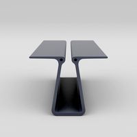
Extruded Table
... extruded table for download as blend, dae, fbx, obj, and stl on turbosquid: 3d models for games, architecture, videos. (1634137)
turbosquid
$2
3D Printer Extruder
...d
royalty free 3d model 3d printer extruder for download as on turbosquid: 3d models for games, architecture, videos. (1537359)
turbosquid
$1
Zombie extruded text
...oyalty free 3d model zombie extruded text for download as obj on turbosquid: 3d models for games, architecture, videos. (1322198)
turbosquid
$4
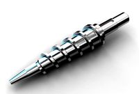
Extruder conical screw
...el extruder conical screw for download as sldpr, ige, and stl on turbosquid: 3d models for games, architecture, videos. (1524433)
turbosquid
$50
3d PRINTER - Extruder
... available on turbo squid, the world's leading provider of digital 3d models for visualization, films, television, and games.
turbosquid
$15
Extruded Table 2
...xtruded table 2 for download as blend, dae, fbx, obj, and stl on turbosquid: 3d models for games, architecture, videos. (1621846)
turbosquid
$10
Maya Extrude Tool
... available on turbo squid, the world's leading provider of digital 3d models for visualization, films, television, and games.
3d_export
$5

world earth extrude map
...world earth extrude map
3dexport
3ddd
$1

Simply Elegant Extruded Tree Coffee Table Design
...ble by link studios. the silhouette of a tree is visible at one angle, extruded from the surface to create the support structure.
Y
turbosquid
$1

Tetera y Galletas y Caf
... available on turbo squid, the world's leading provider of digital 3d models for visualization, films, television, and games.
3ddd
$1

Смеситель Y-CON
...смеситель y-con
3ddd
смеситель , y-con
смеситель y-con
3ddd
$1
Y-Chair
...y-chair
3ddd
tom dixon
y-chair designed by tom dixon,
3ds max + obj, corona
3ddd
$1
Y Chair compilation
....net/products/us/y-chair-sled-base
y chair swivel basehttp://www.tomdixon.net/products/us/y-chair-swivel-base
turbosquid
$190
Y-8
...y-8
turbosquid
royalty free 3d model y-8 for download as max on turbosquid: 3d models for games, architecture, videos. (1658891)
turbosquid
$7
Bench Y
...turbosquid
royalty free 3d model bench y for download as obj on turbosquid: 3d models for games, architecture, videos. (1488746)
turbosquid
$15

bonePile Y
...oyalty free 3d model bonepile y for download as blend and obj on turbosquid: 3d models for games, architecture, videos. (1546374)
turbosquid
$7

Y for Yarn
...d
royalty free 3d model y for yarn model for download as max on turbosquid: 3d models for games, architecture, videos. (1699732)
turbosquid
$2
FONT Y
...quid
royalty free 3d model font y for download as ma and obj on turbosquid: 3d models for games, architecture, videos. (1549457)
3ddd
$1

WOOD-y
...wood-y
3ddd
wooden guy