Thingiverse
Anet A8 & Prusa i3 Compact Dual Extuder Carriage with Front Mount 18mm, 12mm, or 8mm Sensor! by morganlowe
by Thingiverse
Last crawled date: 3 years ago
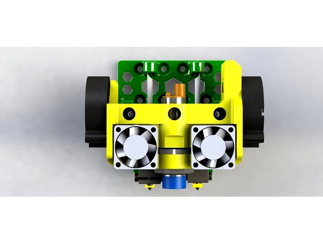
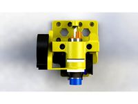
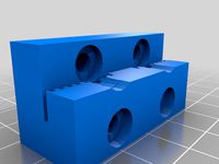
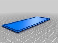
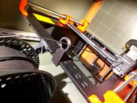
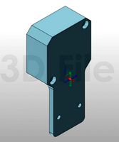
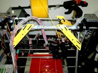
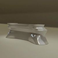
This is my compact version of my other Anet A8 dual extruder heads. This uses two E3D extruders and has bed leveling sensor mounted as close as I could possibly get it.
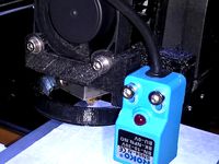
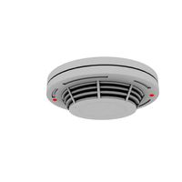
Now i had nothing but bad luck with these sensors and this is my last design to use them. They are pretty much garbage. Constant failures, barely repeatable results where I have never had BLTouch die and the results are always perfect. Please consider a BLTouch and the newer designs.
BL Touch version here: https://www.thingiverse.com/thing:3160905
Get the chain here: https://www.thingiverse.com/thing:3179124
Here's the build timelapse!https://youtu.be/tFMRo3YnjW0
This is the front mount sensor version! Everything FITS!
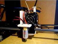
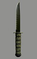
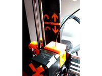
You can see in the last 4 photos that the head does not heat up much. It's been prionted in heat change PLA that shifts brown to green at about 35c. Hour into this print and it's barely changed since the cold air from the fans passes through the print.
I made this one to put the sensor as close as possible to the heads. I think this is the tightest it could possibly be.
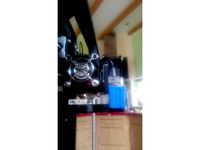
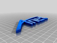
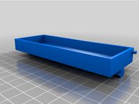
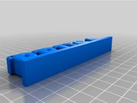
It has built in cooling ducts for the extruders and mounts for the stock 30mm fans built in. I used Mistral 2.1A 4.5 from www.thingiverse.com/thing:2121279 as my cooling ducts. You need to mirror one for the other side but they fit and work great. In theory this should fit any Anet A9 fan duct.
The back is just the no sensor one from my other mount: https://www.thingiverse.com/thing:2734717
The fan spacers are included to help clearance the fans. Different ducts fit different ways but with the one listed above I found 2 spacers on ear screw worked great. For the lower screw on the side fans be sure to put it through the mount first then spacers and fan with the nut on the fan so it clears the 30mm cooling fans in the front. See pictures!
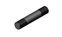
The three clamping screws use Socket Head M4x30 or 35mm with nuts. The head cannot be hex like a bolt or it will not fit in the recess. I found socket head best for torque and easy of use. For the fan mounts I used M3x30m with nuts.
To print choose your parts:
18mm Sensor With Chain
12mm Sensor With Chain
8mm Sensor With Chain
To use this please read below!
See my Thing https://www.thingiverse.com/thing:2783450 For how to setup Marlin firmware!
See https://www.thingiverse.com/thing:2784817 for how to install RAMPS on your printer.
Enable RAMPS boards, this is for the common ones like https://goo.gl/XW91zh [Amazon.com link] PLEASE pay attention and be sure to choose the correct code for your motherboards. See boards.h in the Skynet firmware for a list.
define MOTHERBOARD BOARD_RAMPS_14_EEB
Enable dual extruders:
define EXTRUDERS 2
Offsets for the extruders:
define HOTEND_OFFSET_X {0.0, -35.00}
define HOTEND_OFFSET_Y {0.0, 0.00}
For the probe it's :
define X_PROBE_OFFSET_FROM_EXTRUDER 17 // X offset: -left +right [of the nozzle]
define Y_PROBE_OFFSET_FROM_EXTRUDER -23 // Y offset: -front +behind [the nozzle]
define Z_PROBE_OFFSET_FROM_EXTRUDER -0.5 // Z offset: -below +above [the nozzle Set this to your machine. I used a .5mm thick print put between the bed and probe with the nozzle touching the bed to start.]
And the travel limits are:
// Travel limits after homing (units are in mm)
define X_MAX_POS 240
define X_MIN_POS -10
define Y_MAX_POS 230
define Y_MIN_POS -13
define Z_MAX_POS 230
define Z_MIN_POS 0
You also must set
// Set the boundaries for probing (where the probe can reach).
define LEFT_PROBE_BED_POSITION 20
define RIGHT_PROBE_BED_POSITION 200
define BACK_PROBE_BED_POSITION 190
define FRONT_PROBE_BED_POSITION 20
I have made a guide in PDF form available here https://goo.gl/1s8jSR for setting the offsets. You will need a serial connection to your printer and I found using Octoprint is really easy.
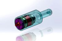
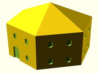
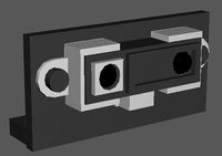
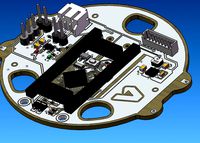
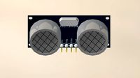
Here's a crapCAD schematic of the optocoupler board I made to run the 12v probe completely isolated from the RAMPS board.
Enjoy! Like! Leave a comment! Thank you!
Update 10/16/2018 Added a little bit of play to the second extruder up and down to allow adjustment to meet the level of it's neighbor. This is done by loosening the clamp with the head resting on a level platform. Adjust both to level each other and tighten the clamp!
Now I admit I have not tested or printed this yet myself. I ordered parts to put dual heads back on the printer and will get this done in the next few days.
Let me know if anyone tries it!
Now i had nothing but bad luck with these sensors and this is my last design to use them. They are pretty much garbage. Constant failures, barely repeatable results where I have never had BLTouch die and the results are always perfect. Please consider a BLTouch and the newer designs.
BL Touch version here: https://www.thingiverse.com/thing:3160905
Get the chain here: https://www.thingiverse.com/thing:3179124
Here's the build timelapse!https://youtu.be/tFMRo3YnjW0
This is the front mount sensor version! Everything FITS!
You can see in the last 4 photos that the head does not heat up much. It's been prionted in heat change PLA that shifts brown to green at about 35c. Hour into this print and it's barely changed since the cold air from the fans passes through the print.
I made this one to put the sensor as close as possible to the heads. I think this is the tightest it could possibly be.
It has built in cooling ducts for the extruders and mounts for the stock 30mm fans built in. I used Mistral 2.1A 4.5 from www.thingiverse.com/thing:2121279 as my cooling ducts. You need to mirror one for the other side but they fit and work great. In theory this should fit any Anet A9 fan duct.
The back is just the no sensor one from my other mount: https://www.thingiverse.com/thing:2734717
The fan spacers are included to help clearance the fans. Different ducts fit different ways but with the one listed above I found 2 spacers on ear screw worked great. For the lower screw on the side fans be sure to put it through the mount first then spacers and fan with the nut on the fan so it clears the 30mm cooling fans in the front. See pictures!
The three clamping screws use Socket Head M4x30 or 35mm with nuts. The head cannot be hex like a bolt or it will not fit in the recess. I found socket head best for torque and easy of use. For the fan mounts I used M3x30m with nuts.
To print choose your parts:
18mm Sensor With Chain
12mm Sensor With Chain
8mm Sensor With Chain
To use this please read below!
See my Thing https://www.thingiverse.com/thing:2783450 For how to setup Marlin firmware!
See https://www.thingiverse.com/thing:2784817 for how to install RAMPS on your printer.
Enable RAMPS boards, this is for the common ones like https://goo.gl/XW91zh [Amazon.com link] PLEASE pay attention and be sure to choose the correct code for your motherboards. See boards.h in the Skynet firmware for a list.
define MOTHERBOARD BOARD_RAMPS_14_EEB
Enable dual extruders:
define EXTRUDERS 2
Offsets for the extruders:
define HOTEND_OFFSET_X {0.0, -35.00}
define HOTEND_OFFSET_Y {0.0, 0.00}
For the probe it's :
define X_PROBE_OFFSET_FROM_EXTRUDER 17 // X offset: -left +right [of the nozzle]
define Y_PROBE_OFFSET_FROM_EXTRUDER -23 // Y offset: -front +behind [the nozzle]
define Z_PROBE_OFFSET_FROM_EXTRUDER -0.5 // Z offset: -below +above [the nozzle Set this to your machine. I used a .5mm thick print put between the bed and probe with the nozzle touching the bed to start.]
And the travel limits are:
// Travel limits after homing (units are in mm)
define X_MAX_POS 240
define X_MIN_POS -10
define Y_MAX_POS 230
define Y_MIN_POS -13
define Z_MAX_POS 230
define Z_MIN_POS 0
You also must set
// Set the boundaries for probing (where the probe can reach).
define LEFT_PROBE_BED_POSITION 20
define RIGHT_PROBE_BED_POSITION 200
define BACK_PROBE_BED_POSITION 190
define FRONT_PROBE_BED_POSITION 20
I have made a guide in PDF form available here https://goo.gl/1s8jSR for setting the offsets. You will need a serial connection to your printer and I found using Octoprint is really easy.
Here's a crapCAD schematic of the optocoupler board I made to run the 12v probe completely isolated from the RAMPS board.
Enjoy! Like! Leave a comment! Thank you!
Update 10/16/2018 Added a little bit of play to the second extruder up and down to allow adjustment to meet the level of it's neighbor. This is done by loosening the clamp with the head resting on a level platform. Adjust both to level each other and tighten the clamp!
Now I admit I have not tested or printed this yet myself. I ordered parts to put dual heads back on the printer and will get this done in the next few days.
Let me know if anyone tries it!
Similar models
thingiverse
free
Anet A8 & Prusa i3 Extuder Carriage with Front Mount 18mm, 12mm, 8mm Sensor or No Sensor and Options! by morganlowe
....
updates:
2/11/18 changed fillet on fan mount to make it easier to print.
please like, comment and share! thank you and enjoy!
thingiverse
free

Anet A8 Front Fan Sensor Mount 18 mm by buzzkc
...://www.thingiverse.com/thing:2506274
the wiring schematic and parts list for my sensor: https://www.thingiverse.com/thing:2758533
thingiverse
free

Lion Mount Dual Extruder BL Touch Front Sensor Edition for Anet A8 & Prusa i3! by morganlowe
...ordered parts to put dual heads back on the printer and will get this done in the next few days.
let me know if anyone tries it!
thingiverse
free

Hypercube Bushing Probe Inductive Sensor Mount by butchja
...#define front_probe_bed_position 64
if you are interested in the pictured fan duct, seehttps://www.thingiverse.com/thing:2517118
thingiverse
free
Anet A6 BLTouch/3DTouch mount (front) by thvranken
...isplay or with command m851) and saved to the eeprom (using the display or with command m500), in my case, this was around -2 mm.
thingiverse
free

Lion Mount Front BLTouch Sensor Bowden Carriage for Anet A8 & Prusa i3! by morganlowe
...ound the mount for the bltouch and made a recess so it can go up into the mount further allowing you to use the mounting springs.
thingiverse
free

Anet A8 E3D V6 Bowden Dual Extruder Mount Prusa i3 Clone X Carriage *REAR SENSOR* by morganlowe
...e
4) 40mm m4 screws and nuts for the cap, 3 of them
5) 50mm blower fan
6) wires, connectors, crimpers, and a soldering iron help.
thingiverse
free

Anet A8 12 mm front sensor fan mount Remix by MarkerDave
...t_probe_bed_position 25
define right_probe_bed_position 194
define back_probe_bed_position 170
define front_probe_bed_position 20
thingiverse
free

BLTouch Bracket for Charlstruder with E3D v5 by Scooterbot
...
charlstruder extruder: https://www.thingiverse.com/thing:678089
recommended fan duct: https://www.thingiverse.com/thing:1323958
thingiverse
free

AutoLevel Probe Mount + Fan Duct for Geeetech I3 ProB by uniap
..._extruder -40 // y offset: -front +behind [the nozzle]
tip: connect the fan cable to pin d9 of the ramps 1.4 for better control.
Morganlowe
thingiverse
free

AM8 - 3DLS Gantry Position Tool by morganlowe
...am8 - 3dls gantry position tool by morganlowe
thingiverse
just a simple thing to set where the gantry should go!
thingiverse
free
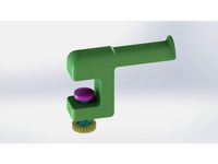
Edge Clamp Spool Holder by morganlowe
...ng. a spool holder to clamp on the edge of a desk or table. all 3d printed. fits all the spools i have ever encountered.
thanks!
thingiverse
free
Filler Jig for KING Joints by morganlowe
... joints for the larger king pre-rolls.
print upright with support everywhere on the funnel side, no support needed on the poker.
thingiverse
free
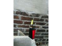
Bolt Shaped Drip Tip! by morganlowe
...eaded bolt with m12x1.25 threads for your e-cig!
see it printed here: https://youtu.be/poxalukhzve
enjoy, don't get screwed!
thingiverse
free
Drawing stand for Surface Pro by morganlowe
...ng. made it for my artist friend and he's loving it. uses 14 6mmx2mm round rubber feet. 10 on top 4 on the bottom.
thank you
thingiverse
free
Panasonic Toughbook CF-U1 HDD Cover by morganlowe
...s is a cover without a caddy for the cf-u1 ssd mod
just made and tested it with my mk2 cf-u1. fits and seals properly.
thank you!
thingiverse
free
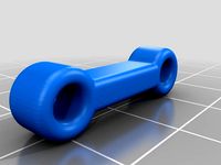
Bowden Tube Bone by morganlowe
...ides snug over the tubes and just keeps them from going nuts. i might be the only person ever to need this but here it is!
enjoy!
thingiverse
free
Trowel for 50mm Concrete Curb by morganlowe
...ts in 2 parts with 3.8mm plastite screws. kinda niche but who knows, maybe you can use it! source files included, solidworks 2017
thingiverse
free

Spark Plug Inspired Drip Tip by morganlowe
...y universal. the outside hex is 19mm and it's 20mm tall without the tank nipple. it uses a 1x7mm o ring. print with support!
thingiverse
free
Spark Plug Inspired Drip Tip Tall Version by morganlowe
...:3013945
i found these print really well upside down with no support and a nice brim to stick it down. they are very thin walled.
Extuder
3d_export
$10

Iphone 13 pro max
...in 3ds max+vray and<br>other 3d softwares that suported thos type of file format<br>- realistic render image included
thingiverse
free

Dual Extuder chessboard by i3Dsd
...dual extuder chessboard by i3dsd
thingiverse
just a sumple chessboard for a dual extruder printer.
thingiverse
free

delta micromake extuder fan by yandem
...use a long nozzle
i will make the cooling system more powerfull
micromake extuder parts:https://www.thingiverse.com/thing:1807142
thingiverse
free

Longer LK4/5 Pro extuder Mod for TPU with wire holder by Spiga76
...longer lk4/5 pro extuder mod for tpu with wire holder by spiga76
thingiverse
thingiverse
free

Adimlab Gantry X linear rail carriage bracket MK8 Extuder
...he attachment to solve the issues with part warping due to heat. this carriage weight 29 grams. print with 50% infill using petg.
thingiverse
free

Overwatch logo extuder indicator by Hatchet86
...lip together just fine but i actually recommend using super glue.the magnet used is a 6x3 mm. you should also glue on the magnet.
thingiverse
free

Support for MK8 Head with extuder for ANET A2 by pinpak
...et a2 by pinpak
thingiverse
i made this support for mounth mk8 head with extrusor and now i can print flexible material like tpu
thingiverse
free

Ender 3 Extuder Simple Extension
...t that moving the extruder a bit might work.
just 4 x m4 screws and you're good to go.
no need for any change or more wiring.
thingiverse
free

Parametric Wade's extuder bowden adapter by ckaos
... to a wade's type extruder driver
mount the whole thing (extruder driver + bowden cable) on the top threaded rods of a reprap
thingiverse
free

TRONXY P802MA direct drive extuder fan shield for e3dv6 mod by atosys
...tronxy p802ma direct drive extuder fan shield for e3dv6 mod by atosys
thingiverse
extruder cooling fan shield for tronxy p802ma.
18Mm
3ddd
$1

3D Wall Panels Ripples
...down to suit your requirements. interior base material is 18mm e0 mr mdf or for outdoors, waterproof 18mm thick...
3ddd
$1

3D Wall Panels Reflections
...down to suit your requirements. interior base material is 18mm e0 mr mdf or for outdoors, waterproof 18mm thick...
3d_export
$18

hands ring
...hands ring 3dexport current ring size is 18mm<br>ring rail size is...
3d_export
$10

armchair
...machine height 678mm width 785mm is long 545 plywood 18mm ready for production,solid / surface...
3d_export
$15

rocking chair
...height 901mm. width 990mm. is long 594 mm. plywood 18mm.solid / surface...
3d_export
free

coffee table
...coffee table 3dexport coffee table for cnc machines 18mm plywood. dimensions: height 420mm., length 700mm., width 342mm.. the...
3ddd
$2

3D Wall Panels Scallops
...down to suit your requirements. interior base material is 18mm e0 mr mdf or for outdoors, waterproof 18mm thick...
3ddd
$1

3D Wall Panels Stars
...down to suit your requirements. interior base material is 18mm e0 mr mdf or for outdoors, waterproof 18mm thick...
3d_export
$15

parametric sofa
...machine and visualization without textures. solid modeling. drawing is present.18mm plywood the size 1314mm. 754mm. depth...
3d_export
$11

solitaire ring
...solitaire ring 3dexport current ring size is 18mm<br>ring rail size is 56.5<br>stone size 4.5 mm....
A8
turbosquid
$47

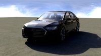
Car A8
...
turbosquid
royalty free 3d model car a8 for download as max on turbosquid: 3d models for games, architecture, videos. (1196060)
turbosquid
$50
Audi A8
...yalty free 3d model audi a8 for download as 3dm, obj, and fbx on turbosquid: 3d models for games, architecture, videos. (1580187)
turbosquid
$15

Audi A8
...lty free 3d model audi a8 for download as obj, fbx, and blend on turbosquid: 3d models for games, architecture, videos. (1387519)
turbosquid
$500

Audi A8
... available on turbo squid, the world's leading provider of digital 3d models for visualization, films, television, and games.
3d_export
$5

Audi A8 3D Model
...audi a8 3d model
3dexport
audi a8 cars car
audi a8 3d model ma 20351 3dexport
3d_export
$5

Audi A8 3D Model
...audi a8 3d model
3dexport
3d model of audi a8
audi a8 3d model badyaka 12136 3dexport
3d_ocean
$89

Audi A8 2010
...usiness car car class class f f german german luxury luxury s s s8 s8 sedan sedan vehicle vehicle
new audi a8 2010 detaled model.
turbosquid
$39

A8 2018
...a8 2018 for download as 3ds, obj, wrl, c4d, fbx, dae, and stl on turbosquid: 3d models for games, architecture, videos. (1345349)
turbosquid
free

audi a8 l
...rbosquid
royalty free 3d model audi a8 l for download as obj on turbosquid: 3d models for games, architecture, videos. (1663016)
3d_ocean
$45

Audi A8 restyled
...our door vehicle was created in blender3d 2.62.realistic renderings were created with yafaray 0.1.2 realistic plugin.rendering...
12Mm
turbosquid
$30

Settings 4mm to 12mm
...oyalty free 3d model settings 4mm to 12mm for download as 3dm on turbosquid: 3d models for games, architecture, videos. (1548862)
3d_export
$10

A box of bullets of 12mm caliber
...a box of bullets of 12mm caliber
3dexport
a box of 12mm caliber bullets for hunting small game and poultry.
turbosquid
$7

Straight chisel 12mm
... chisel 12mm for download as max, 3ds, dae, dwg, fbx, and obj on turbosquid: 3d models for games, architecture, videos. (1601806)
turbosquid
$7
Straight chisel 12mm
... chisel 12mm for download as max, 3ds, dae, dwg, fbx, and obj on turbosquid: 3d models for games, architecture, videos. (1601075)
turbosquid
$1

Linear Bearing 12mm ID
... available on turbo squid, the world's leading provider of digital 3d models for visualization, films, television, and games.
turbosquid
$1
Rc Paddle Tire 12mm hex
... available on turbo squid, the world's leading provider of digital 3d models for visualization, films, television, and games.
3d_export
free

fifa world cup qatar 2022
...of the magnet for the stand( diameter 52mm, height 12mm, the magnet in the ground(diameter 30mm, height...
3d_ocean
$8

Roche Bobois - Tenere Coffee Table
...table tenere roche bobois – tenere coffee table – 12mm glued glass top, frame in concrete effect finish, single...
3d_export
$10
welding fixture for side beam of train bogie
...vertical plate wall thickness is 14mm, the web is 12mm and the middle sections are distributed with 10mm reinforced...
3d_export
$10

bracelet clasp lock12mm x 24mm
...ach others and then enjoy your bracelet. i don't recommend to rescale this model, order to create the lock same as your wish.
Anet
thingiverse
free

Anet by derbodesign
...anet by derbodesign
thingiverse
logo anet
thingiverse
free
Anet e10 , Anet v1.0 by jonathan_943D
...anet e10 , anet v1.0 by jonathan_943d
thingiverse
soporte de ventilador de 80mm, para controladora anet v1.0
thingiverse
free
Anet A8 Anet AM8 Y belt holder
...anet a8 anet am8 y belt holder
thingiverse
anet a8 anet am8 y belt holder
thingiverse
free
Anet A8 Probe Bracket for anet sensor by chelrix
...anet a8 probe bracket for anet sensor by chelrix
thingiverse
anet a8 probe bracket for anet official sensor and marlin firmware
thingiverse
free
Anet logo by JUST3D_PRNTNG
...anet logo by just3d_prntng
thingiverse
anet logo
thingiverse
free
Fan nozzle for Anet A8 with original Anet levelsensor by peteruhlmann
...et levelsensor by peteruhlmann
thingiverse
here is an improved fan nozzle for the anet a8 with original level sensor from anet.
thingiverse
free
Anet Et4 Box
...anet et4 box
thingiverse
tool box for anet et4
thingiverse
free
Anet Logo by Superflex_Plastic_Fantastic
...anet logo by superflex_plastic_fantastic
thingiverse
anet logo to incorporate into designs.
thingiverse
free
Box for Anet ET4
...box for anet et4
thingiverse
this is a simple box for tool of anet et4
thingiverse
free

Anet V1.0 Board Kühlung (80mm Lüfter) / Anet A8 by MadCre8
...anet v1.0 board kühlung (80mm lüfter) / anet a8 by madcre8
thingiverse
anet v1.0 board kühlung (80mm lüfter) / anet a8
Carriage
archibase_planet
free
Carriage
...arriage
archibase planet
perambulator baby carriage pram
carriage n250908 - 3d model (*.gsm+*.3ds) for interior 3d visualization.
3d_export
free
carriage
...carriage
3dexport
old fashion carriage model, more files here:
turbosquid
$140

Carriage
...urbosquid
royalty free 3d model carriage for download as max on turbosquid: 3d models for games, architecture, videos. (1482052)
turbosquid
$25
Carriage
...urbosquid
royalty free 3d model carriage for download as max on turbosquid: 3d models for games, architecture, videos. (1285944)
3d_export
free
carriage
...carriage
3dexport
game cart
3d_ocean
$15
Barrel Carriage
...ieval oak old transport wheels wine wood
this model contains a barrel and a carriage. it is a medieval type of wood oak carriage.
turbosquid
$40
Carriage
...ty free 3d model carriage for download as obj, fbx, and blend on turbosquid: 3d models for games, architecture, videos. (1290094)
turbosquid
free

Carriage
...yalty free 3d model carriage for download as ma, obj, and fbx on turbosquid: 3d models for games, architecture, videos. (1239157)
3d_export
$5
Medieval carriage
...medieval carriage
3dexport
medieval carriage in fairy style
turbosquid
$58

Carriage
...d model carriage with scene for download as max, obj, and fbx on turbosquid: 3d models for games, architecture, videos. (1276262)
8Mm
turbosquid
$50
8MM CAMERA.max
... available on turbo squid, the world's leading provider of digital 3d models for visualization, films, television, and games.
turbosquid
$19
kodak 8mm
... available on turbo squid, the world's leading provider of digital 3d models for visualization, films, television, and games.
turbosquid
$1
Brass Bush Bearing 8mm ID
... available on turbo squid, the world's leading provider of digital 3d models for visualization, films, television, and games.
turbosquid
$20
wrench big collection from 8mm to 32mm
...llection from 8mm to 32mm for download as obj, fbx, and sldas on turbosquid: 3d models for games, architecture, videos. (1438111)
turbosquid
$1
Flexible Shaft Coupling 6mm x 8mm
... available on turbo squid, the world's leading provider of digital 3d models for visualization, films, television, and games.
turbosquid
$1
Flexible shaft coupling 5mm x 8mm
... available on turbo squid, the world's leading provider of digital 3d models for visualization, films, television, and games.
turbosquid
$15

German WWII Breda MG-8mm Ammo Box (Low Poly)
...g-8mm ammo box (low poly) for download as obj, fbx, and blend on turbosquid: 3d models for games, architecture, videos. (1395526)
3ddd
free

Treasures of the Sea
...treasures of the sea 3ddd бижутерия d=8mm ...
3d_export
$5
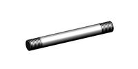
double thread screw
...thread length: 10 mm total length: 41 mm diameter: 8mm ...
3d_export
$5
large double thread screw
...thread length: 10 mm total length: 115 mm diameter: 8mm ...
Compact
3d_export
$5

compact freezer
...compact freezer
3dexport
the compact freezer is product about refrigeration machine
3d_ocean
$8
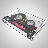
Compact Cassette
...
80s album analog audio cartridge cassette compact digital electronics lp mp3 music play record sound tape vinyl
compact cassette
design_connected
$20
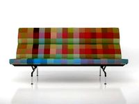
Eames Compact
...eames compact
designconnected
herman miller eames compact computer generated 3d model. designed by eames, charles.
3d_ocean
$2

Compact Disc
...compact disc
3docean
album audio cd compact disc dvd laser disc movie music
a cd
3d_export
$10

land compacter
...land compacter
3dexport
turbosquid
$1
Compact knife
...quid
royalty free 3d model compact knife for download as obj on turbosquid: 3d models for games, architecture, videos. (1557900)
3d_export
$12
compact rotary broach
...compact rotary broach
3dexport
compact tool for drilling hexagonal holes in lathes!
turbosquid
free

Lada Compact
... 3d model lada compact for download as max, max, max, and fbx on turbosquid: 3d models for games, architecture, videos. (1623122)
turbosquid
$59

Compact Truck
... available on turbo squid, the world's leading provider of digital 3d models for visualization, films, television, and games.
turbosquid
$50
Compact kitchen
... available on turbo squid, the world's leading provider of digital 3d models for visualization, films, television, and games.
I3
3d_export
$10
suv i3
...suv i3
3dexport
suv i3 2013 series
3d_ocean
$89

BMW i3 2012
...y, in real units of measurement, qualitatively and maximally close to the original. model formats: - *.max (3ds max 2008 scanl...
cg_studio
$99

BMW i3 20143d model
...
cgstudio
.3ds .c4d .fbx .lwo .max .obj - bmw i3 2014 3d model, royalty free license available, instant download after purchase.
cg_studio
$99

BMW i3 20123d model
...tudio
.3ds .c4d .fbx .lwo .max .mb .obj - bmw i3 2012 3d model, royalty free license available, instant download after purchase.
cg_studio
$99

BMW i3 20143d model
...tudio
.3ds .c4d .fbx .lwo .max .mb .obj - bmw i3 2014 3d model, royalty free license available, instant download after purchase.
humster3d
$75

3D model of BMW i3 2014
...
buy a detailed 3d model of bmw i3 2014 in various file formats. all our 3d models were created maximally close to the original.
humster3d
$40

3D model of Kitchen Set I3
...uy a detailed 3d model of kitchen set i3 in various file formats. all our 3d models were created maximally close to the original.
3d_ocean
$30
Kitchen set i3
...ensils oven plates shelves sink table ware
kitchen set i3 include 3d models: cooker, oven, sink, cupboards, table, chair, plates.
3d_ocean
$89

BMW i3 2014
...y, in real units of measurement, qualitatively and maximally close to the original. model formats: - *.max (3ds max 2008 scanl...
cg_studio
$99

BMW i3 Concept 20113d model
...i3
.3ds .c4d .fbx .lwo .max .obj - bmw i3 concept 2011 3d model, royalty free license available, instant download after purchase.
Dual
turbosquid
free

Dual Pistols
...ls
turbosquid
free 3d model dual pistols for download as fbx on turbosquid: 3d models for games, architecture, videos. (1320360)
turbosquid
$2
Dual Axe
...urbosquid
royalty free 3d model dual axe for download as fbx on turbosquid: 3d models for games, architecture, videos. (1332372)
turbosquid
$10
Dual Lesaths
... available on turbo squid, the world's leading provider of digital 3d models for visualization, films, television, and games.
3ddd
$1
плитка Dual Bianco (Испания)
...й плитки venis dual (испания). технические качества: устойчивость к стирания, отличная геометрия, отсутствие проблем при укладке.
turbosquid
$35

Dual Mesh Fonts
...ree 3d model dual mesh fonts for download as ma, obj, and fbx on turbosquid: 3d models for games, architecture, videos. (1352989)
turbosquid
$29

Dual Flask with Bungs
...del dual flask with bungs for download as obj, fbx, and blend on turbosquid: 3d models for games, architecture, videos. (1210512)
turbosquid
$19
Dual Socket Plug
...3d model dual socket plug for download as obj, fbx, and blend on turbosquid: 3d models for games, architecture, videos. (1303912)
turbosquid
$13
Dual Adjustable Pulley
... available on turbo squid, the world's leading provider of digital 3d models for visualization, films, television, and games.
turbosquid
$10

Amoi N809 Dual
... available on turbo squid, the world's leading provider of digital 3d models for visualization, films, television, and games.
turbosquid
$5
Dual Turret Tank
... available on turbo squid, the world's leading provider of digital 3d models for visualization, films, television, and games.
Prusa
turbosquid
$2
Frame Filament Guide Clip-On for Prusa Mk3
...rame filament guide clip-on for prusa mk3 for download as stl on turbosquid: 3d models for games, architecture, videos. (1634730)
3d_export
free
prusa i3 mk3s laser mount for opt lasers
...to learn more about the blue laser technology that conceived the cutting and engraving laser heads from opt lasers, please visit:
turbosquid
free
Prusa small printer adapter holder
...er for download as ipt, skp, dwg, dxf, fbx, ige, obj, and stl on turbosquid: 3d models for games, architecture, videos. (1642936)
3d_export
$30

geisha by jonathan adler
...** i did a 3d printing test in the prusa software, you can find it among the attached images.<br>exchange:<br>.blend...
thingiverse
free

Prusa without Prusa (rc2) by madless
...prusa without prusa (rc2) by madless
thingiverse
just the main part of prusa rc2 faceshield, without writing.
enjoy :)
thingiverse
free
Prusa by acejbc
...prusa by acejbc
thingiverse
prusa knob info
m3 8mm screw
thingiverse
free
Prusa house
...prusa house
thingiverse
how prusa house could look like...
thingiverse
free

Prusa Mk2 "Fake Prusa" LCD cover by anraf1001
...r by anraf1001
thingiverse
version of prusa's lcd cover with "fake prusa" instead of "original prusa"
thingiverse
free
Prusa stabilizator by gutiueugen
...prusa stabilizator by gutiueugen
thingiverse
prusa stabilizator
thingiverse
free
Keychain Prusa by rbarbalho
...keychain prusa by rbarbalho
thingiverse
keychain with text prusa.
Sensor
3d_export
free

parking sensor
...parking sensor
3dexport
car parking sensor
turbosquid
$1
Sensor
... available on turbo squid, the world's leading provider of digital 3d models for visualization, films, television, and games.
3d_export
$5
Smoke sensor
...port
smoke sensor, can be an impressive element for your projects. easy to use, realistic image, low polygon, quality materials.
3d_export
$5
Air Quality Sensor v1
...air quality sensor v1
3dexport
air quality sensor v1
3d_export
$15
float sensor
...e up render. - all parts and materials are logically named. other formats ================= - collada (.dae) - autodesk fbx - obj
turbosquid
$26
Wind sensor C
...free 3d model wind sensor c for download as 3ds, obj, and fbx on turbosquid: 3d models for games, architecture, videos. (1328943)
turbosquid
$26
Wind sensor B
...free 3d model wind sensor b for download as 3ds, obj, and fbx on turbosquid: 3d models for games, architecture, videos. (1328168)
3d_export
$5
ultrasound sensor
...ivers convert ultrasound into electrical signals, and transceivers can both transmit and receive ultrasound. export in: -obj -fbx
3ddd
free
Вытяжка Shindo pallada sensor
... вытяжка
вытяжка shindo pallada sensor. в двух размерах - 600 и 900. текстуры в комплекте.
turbosquid
$52
Wind sensor A B C
...
royalty free 3d model wind sensor a b c for download as fbx on turbosquid: 3d models for games, architecture, videos. (1408406)
Front
archibase_planet
free

Front
...front
archibase planet
facade front bluff
front 3d01a - 3d model (*.gsm+*.3ds) for interior 3d visualization.
3d_export
$5
front fork
...front fork
3dexport
front fork
3d_export
$5
Front Desk
...front desk
3dexport
modern and minimal reception front desk
3d_ocean
$4
Medical Front
...medical front
3docean
horror low medical
medical front
3d_ocean
$5
Front Desk
...front desk
3docean
desk front office reception
office reception counter or front desk. cad file and obj file included.
3ddd
free

Axor WaterDream by Front
...r , waterdream , front
axor waterdream by front
3d_export
$5
front nut eye
...front nut eye
3dexport
front nut eye
3d_export
$5
front screw eye
...front screw eye
3dexport
front screw eye
3d_export
$5

front clamping device
...front clamping device
3dexport
front clamping device
archive3d
free
Front 3D Model
...rchive3d
facade front bluff
front 3d01a - 3d model (*.gsm+*.3ds) for interior 3d visualization.
Mount
3d_export
free

mounting bracket
...mounting plate is the portion of a hinge that attaches to the wood. mounting plates can be used indoors, cabinetry and furniture.
turbosquid
$2

MOUNTING
... available on turbo squid, the world's leading provider of digital 3d models for visualization, films, television, and games.
turbosquid
free

Mounts
... available on turbo squid, the world's leading provider of digital 3d models for visualization, films, television, and games.
turbosquid
free

Mount Fuji
...fuji
turbosquid
free 3d model mount fuji for download as obj on turbosquid: 3d models for games, architecture, videos. (1579977)
3d_export
$5

Headphone mount LR
...headphone mount lr
3dexport
headphone mount l+r
turbosquid
$39

Mount rainier
...quid
royalty free 3d model mount rainier for download as fbx on turbosquid: 3d models for games, architecture, videos. (1492586)
turbosquid
$5

pipe mounting
...quid
royalty free 3d model pipe mounting for download as obj on turbosquid: 3d models for games, architecture, videos. (1293744)
turbosquid
$3

Mounting Tires
...uid
royalty free 3d model mounting tires for download as fbx on turbosquid: 3d models for games, architecture, videos. (1708511)
3d_export
$5

Magnetic GoPro Mount
...pro mount
3dexport
cool magnetic mount for gopro. allows you to mount the camera on flat metal surfaces and get exclusive shots.
turbosquid
$5

Stone Mount
...ty free 3d model stone mount for download as ma, obj, and fbx on turbosquid: 3d models for games, architecture, videos. (1370306)