Thingiverse
Anet A8 lightweight and unobtrusive X-axis cable chain by juh
by Thingiverse
Last crawled date: 3 years ago
Changelog:
Update 2021-03-01: Steve (faultedlogic) made a remix for current A8 models with plastic bearing blocks.
Update 4 (2018-06-17): added countersunk hole for chain fence
Update 3 (2018-06-11): updated left motor mounts for different type of end switch
Update 2 (2018-02-24): added chain fence
Update 1 (2018-02-10): added info on possible z-axis problems
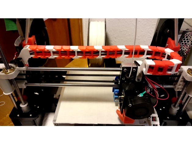
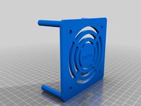
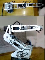
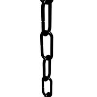
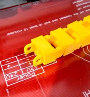
This is a lightweight x-axis cable chain mount solution for the Anet A8. Compared with other solutions,
its chain links are placed upright, thus allowing for a less obtrusive position behind the left z-axis,
it needs less material (filament) and prints faster,
it needs fewer chain elements (23),
although placed behind the z-axis, it is still compatible with the Anet A8 exoskeleton by aeropic.
(However, you might lose a bit of z-build space, see Update 1 below) <-- now obsolete, see update 2
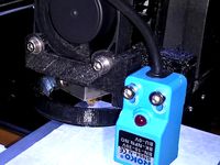
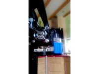
Note: My Anet is from December 2017, please take a close look at the pictures to check if your x-axis motor mount matches.
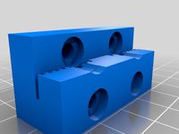
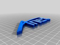
The left-side X-motor chain mount comes in two versions,
a short and basic one (X-motor_mount.stl) for minimalists like me,
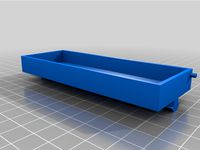
a longer one (X-motor_mount_with_tunnel.stl) with an additional tunnel leading the cables to the backside and with an additional screw fix from behind for extra stability.
In addition to the left and right mounts, you'll need:
23 Cable chain elements from Anet A8 Y Cable Chain by sukhoi27 (download .stl file]).
two screws to remount the x-axis endstop-switch
for the longer left-side version: one screw ca. 3mm x 7mm for fixing the left mount from the backside for additional stability
This is my first published design after ca. 1 month of owning the Anet A8 and learning FreeCAD, and I'm terribly proud of it. Please comment and/or show your makes.
Update 1 (2018-02-10):
As I usually don't print that high I forgot to mention, but depending on your setup you might lose a bit of build height (but see update 2, below). My test results:
If you get your chain to coil nicely in a perfect U-shape or if you move it out of harm's way manually while going up, you could actually go as high as z=240mm (see fourth image, I used the manual method here). Just make sure that the cables at the left don't get caught between the x-axis motor mount and the left side of the lcd back panel.
If your chain doesn't coil perfectly in a U-shape, it could bump into the bottom of the lcd back panel at ca. z=160 (see update 2, below, for a solution). Not sure if maybe movement on the x-axis would actually prevent that from happening, as the problem mostly occurs in the right part of the x-axis. If your object doesn't use the full x-width, printing in the left half of the build plate should eliminate the problem entirely. However, I just wouldn't leave my printer unattended at these kinds of heights, but, hey, an A8 you should never leave unattended for long anyway, so...
If you're using the Anet A8 exoskeleton, the chain might also touch the right hand rod from ca. z=140 upward, but I don't expect that to be a problem if your chain is not too rigid. Also, at the very top the rod mounts will cost you 1-2 cm.
Update 2 (2018-02-24):
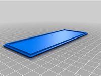
I've been musing about the z>160mm problem for chains that don't coil perfectly like mine (see update 1 above). I considered several approaches, but ended up with the most simple one: a fence which keeps the chain from bending back to the area where it could bump into the lcd back panel. For the moment, I added a standalone solution to be installed permanently beside the carriage chain mount (chain fence (standalone) v3.stl). In order to keep friction to a minimum, you'll need to thoroughly sand the faces of the fence which touch the chain. Maybe you'll even have to sand the corners of some of your right hand chain elements, if they are very sharp. After installing the fence, test it first by manually moving the carriage from left to right, to see if there is absolutely no friction left, before using it in action.
Against my own expectations, I could not observe any negative friction effects on the quality of my prints during my tests in the last week. Nevertheless, I plan on adding another clip-on solution, which allows you to use the fence only for higher prints on demand.
Update 3 (2018-06-18):Lethos1560 reported problems due to a different kind of x-axis end switch provided with his A8. This version of the switch has a longer lever which will collide with the motor mount, preventing the switch from being triggered. I updated both versions of the left motor mount with a second set of mounting holes for the end switch. Position 'A' is for the (as it seems) usual kind, position 'B' for end switches with longer levers. See images for type 'B' (extra image) and type 'A' (all other images) switches.
Update 4 (2018-06-17):Supernova_6969 pointed out that my original design of the chain fence needs a longer screw than the default one and posted a remix with a countersunk hole. Following his comment I updated my design accordingly using his measurements. Thanks again to Supernova_6969!
PS: If you've wondered about changes in the title of this thing, it's just my attempts at search engine optimization.
https://youtu.be/TKg5vBGrwKg
All my Anet A8 designs:
Anet A8 lightweight and unobtrusive X-axis cable chain
Anet A8 slim and robust x-axis tensioner
Anet A8 power supply cover with LCD power meter and switch
Update 2021-03-01: Steve (faultedlogic) made a remix for current A8 models with plastic bearing blocks.
Update 4 (2018-06-17): added countersunk hole for chain fence
Update 3 (2018-06-11): updated left motor mounts for different type of end switch
Update 2 (2018-02-24): added chain fence
Update 1 (2018-02-10): added info on possible z-axis problems
This is a lightweight x-axis cable chain mount solution for the Anet A8. Compared with other solutions,
its chain links are placed upright, thus allowing for a less obtrusive position behind the left z-axis,
it needs less material (filament) and prints faster,
it needs fewer chain elements (23),
although placed behind the z-axis, it is still compatible with the Anet A8 exoskeleton by aeropic.
(However, you might lose a bit of z-build space, see Update 1 below) <-- now obsolete, see update 2
Note: My Anet is from December 2017, please take a close look at the pictures to check if your x-axis motor mount matches.
The left-side X-motor chain mount comes in two versions,
a short and basic one (X-motor_mount.stl) for minimalists like me,
a longer one (X-motor_mount_with_tunnel.stl) with an additional tunnel leading the cables to the backside and with an additional screw fix from behind for extra stability.
In addition to the left and right mounts, you'll need:
23 Cable chain elements from Anet A8 Y Cable Chain by sukhoi27 (download .stl file]).
two screws to remount the x-axis endstop-switch
for the longer left-side version: one screw ca. 3mm x 7mm for fixing the left mount from the backside for additional stability
This is my first published design after ca. 1 month of owning the Anet A8 and learning FreeCAD, and I'm terribly proud of it. Please comment and/or show your makes.
Update 1 (2018-02-10):
As I usually don't print that high I forgot to mention, but depending on your setup you might lose a bit of build height (but see update 2, below). My test results:
If you get your chain to coil nicely in a perfect U-shape or if you move it out of harm's way manually while going up, you could actually go as high as z=240mm (see fourth image, I used the manual method here). Just make sure that the cables at the left don't get caught between the x-axis motor mount and the left side of the lcd back panel.
If your chain doesn't coil perfectly in a U-shape, it could bump into the bottom of the lcd back panel at ca. z=160 (see update 2, below, for a solution). Not sure if maybe movement on the x-axis would actually prevent that from happening, as the problem mostly occurs in the right part of the x-axis. If your object doesn't use the full x-width, printing in the left half of the build plate should eliminate the problem entirely. However, I just wouldn't leave my printer unattended at these kinds of heights, but, hey, an A8 you should never leave unattended for long anyway, so...
If you're using the Anet A8 exoskeleton, the chain might also touch the right hand rod from ca. z=140 upward, but I don't expect that to be a problem if your chain is not too rigid. Also, at the very top the rod mounts will cost you 1-2 cm.
Update 2 (2018-02-24):
I've been musing about the z>160mm problem for chains that don't coil perfectly like mine (see update 1 above). I considered several approaches, but ended up with the most simple one: a fence which keeps the chain from bending back to the area where it could bump into the lcd back panel. For the moment, I added a standalone solution to be installed permanently beside the carriage chain mount (chain fence (standalone) v3.stl). In order to keep friction to a minimum, you'll need to thoroughly sand the faces of the fence which touch the chain. Maybe you'll even have to sand the corners of some of your right hand chain elements, if they are very sharp. After installing the fence, test it first by manually moving the carriage from left to right, to see if there is absolutely no friction left, before using it in action.
Against my own expectations, I could not observe any negative friction effects on the quality of my prints during my tests in the last week. Nevertheless, I plan on adding another clip-on solution, which allows you to use the fence only for higher prints on demand.
Update 3 (2018-06-18):Lethos1560 reported problems due to a different kind of x-axis end switch provided with his A8. This version of the switch has a longer lever which will collide with the motor mount, preventing the switch from being triggered. I updated both versions of the left motor mount with a second set of mounting holes for the end switch. Position 'A' is for the (as it seems) usual kind, position 'B' for end switches with longer levers. See images for type 'B' (extra image) and type 'A' (all other images) switches.
Update 4 (2018-06-17):Supernova_6969 pointed out that my original design of the chain fence needs a longer screw than the default one and posted a remix with a countersunk hole. Following his comment I updated my design accordingly using his measurements. Thanks again to Supernova_6969!
PS: If you've wondered about changes in the title of this thing, it's just my attempts at search engine optimization.
https://youtu.be/TKg5vBGrwKg
All my Anet A8 designs:
Anet A8 lightweight and unobtrusive X-axis cable chain
Anet A8 slim and robust x-axis tensioner
Anet A8 power supply cover with LCD power meter and switch
Similar models
thingiverse
free

Anet A8 Cablechain Mount for X and Z axis by noisyboy1308
... chain you use has the wrong end.
-update 1 2.1.2018
added v2 version of the mount. slight design changes for better printability
thingiverse
free

Anet A8 X axis Cable chain mounts
...anet a8 x axis cable chain mounts
thingiverse
x motor and extruder mount for installing a cable chain on the anet a8.
thingiverse
free

Cable_Chain_X_Motor_Mount by AUREL_14
... need z end-stop support on the cable chain x motor mount.
i design a mount without the support.
thanks for comments and likes :)
thingiverse
free

Anet A8 I3 X-Axis Cable Chain Mounts by auctionarmsceo
... i guilt the carriage mount vertically in openscad, but you should rotate it 90 degress, and then use supports when you print it.
thingiverse
free

Anet A8 Plus 10mm X 15mm Cable Chain Mounts
...to hold the switch on.
for the regular anet a8: use the original screws provided for both.
i purchased the screws at home depot.
thingiverse
free

Anet A8 slim and robust x-axis tensioner by juh
...from z-axis to x-axis rods to prevent z-axis bending (similar to many others e.g. this or this) allows to...
thingiverse
free

Anet A8 bowden extruder x-axis mount by stonemore
...o put an m3 screw for the z-limit switch. i used this thing: https://www.thingiverse.com/thing:1776429 to mount the limit switch.
thingiverse
free

Adjustable Z Stop Anet A8 by AntiAndi
...adjustable z stop anet a8 by antiandi
thingiverse
adjustable z-stop to mount on x-motor with cable chain
thingiverse
free

Z cable Chain by Kanawati
... the standard acrylic frame.
please note that you have to replace 2 of the screws of the stepper motor with a +5 mm longer screws
thingiverse
free

Anet A8 Z-axis cable chain by oh5gzr
...temperature sensor
extruder stepper motor cooling fan
extruder nozzle cooling fan
prepare yourself for some serious soldering! :)
Juh
thingiverse
free

Rolle für Bauhaus Rollcontainer by juh
...ht viel aus (s. foto).
https://www.bauhaus.info/rollcontainer-buerocontainer/rollcontainer/p/20040837
0.2/0.3 mm petg 20% infill.
thingiverse
free

fischertechnik connecting block 7.5mm by juh
...gs.
please consider leaving a "like" as a token of appreciation for my work.
find my other fischertechnik designs here.
thingiverse
free

fischertechnik mini motor replacement gears by juh
...;-)
please consider leaving a "like" as a token of appreciation for my work.
find my other fischertechnik designs here.
thingiverse
free

Juh's Anet A8 lightweight and unobtrusive X-axis cable chain, remixed for plastic bearing blocks by faultedlogic
...ve configuration, don't change anything. if you find your links kinking, perhaps you could give the double wide fence a try.
thingiverse
free

fischertechnik pneumatic 12V air compressor by juh
...ead
please consider leaving a "like" as a token of appreciation for my work.
find my other fischertechnik designs here.
thingiverse
free

Allit EuroPlus Flex 37-15 organizer boxes by juh
...8,5 mm
48,5 x 66,5 mm
note: if you are looking to replace the actual boxes, have a look at allit europlus flex insert by noloxs.
thingiverse
free

fischertechnik pneumatic mini air compressor by juh
...ttps://forum.ftcommunity.de/viewtopic.php?f=15&t=4821
https://youtu.be/q3hnslee3_o
find my other fischertechnik designs here.
thingiverse
free
Anet A8 slim and robust x-axis tensioner by juh
...btrusive x-axis cable chain
anet a8 slim and robust x-axis tensioner
anet a8 power supply cover with lcd power meter and switch
thingiverse
free

Anet A8 Plus Lightweight and Unobtrusive X-axis Cable chain by faultedlogic
...of juh, and was designed for the anet a8. juh#39;s model was created for the classic anet a8. by...
thingiverse
free

Anet A8 power supply cover with LCD power meter and switch by juh
...btrusive x-axis cable chain
anet a8 slim and robust x-axis tensioner
anet a8 power supply cover with lcd power meter and switch
Unobtrusive
3ddd
$1

Вытяжной вентилятор Airflow ICON 15
...into the wall or ceiling, it is stylish and unobtrusive even in the smallest space. the quiet, powerful axial...
3d_export
free

Ypperlig Floor Lamp
...uses with suitable non-glare light that comes from its unobtrusive low slim figure.<br>objects: 3<br>vertices: 28804<br>edges: 57472<br>faces: 28672<br>triangles:...
3ddd
free

de sede \ DS-161
...a considerably lighter feel. significant, well-proportioned aluminium frame. an unobtrusive all-rounder for the commercial and residential...
3ddd
$1

On Line by Eden Design
...of this light source lies in its slenderness and unobtrusiveess; the simplicity of the fixtures’ design makes that it...
3d_export
$12

anthony - dining chair
...with a soft velvet fabric are supported by an unobtrusive wood structure with an almost invisible brass line outlining...
3d_export
$5

Stylish Italian chair Geo by Saba Italia in a modern style
...interior. delicate, does not eat up space, soft and unobtrusive the design of geo is unique - voluminous, but...
3ddd
free

Подвесной светильник SALT by ARKOSLIGHT
...thus ensuring it goes unnoticed. besides being minimalist and unobtrusive this dissipator achieves excellent heat control and enables salt,...
3ddd
$1

Подвесной светильник SALT PC by ARKOSLIGHT
...thus ensuring it goes unnoticed. besides being minimalist and unobtrusive this dissipator achieves excellent heat control and enables salt,...
thingiverse
free

Unobtrusive frame brace by spope
...aded rod left protruding from the upper x axis frame.
you also need to print four of these http://www.thingiverse.com/thing:34134
thingiverse
free

Unobtrusive Anet A6 X axis belt tensioner by sjpeters
...ing the tensioning screw.
the parametric freecad files (version 0.17 daily) are located at speters @ githubgist / spanner3.fcstd
Lightweight
design_connected
$11

Lightweight
...lightweight
designconnected
foscarini lightweight pendant lights computer generated 3d model. designed by tom dixon.
turbosquid
$15

Lightweight
...y free 3d model lightweight for download as max, obj, and fbx on turbosquid: 3d models for games, architecture, videos. (1361264)
turbosquid
$2

Lightweight Shield
... available on turbo squid, the world's leading provider of digital 3d models for visualization, films, television, and games.
turbosquid
$29

Lightweight Pine Chair
... available on turbo squid, the world's leading provider of digital 3d models for visualization, films, television, and games.
turbosquid
$20

Lightweight Task Chair
... available on turbo squid, the world's leading provider of digital 3d models for visualization, films, television, and games.
turbosquid
$20

Chandelier Lightweight Foscarini
... available on turbo squid, the world's leading provider of digital 3d models for visualization, films, television, and games.
turbosquid
$2

futuristic lightweight wheel
... available on turbo squid, the world's leading provider of digital 3d models for visualization, films, television, and games.
3d_export
free

Lightweight structure system animated
...lightweight structure system animated
3dexport
https://www.dock4all.com/
turbosquid
$15

03 LIGHTWEIGHT PATTERN WALL
...ghtweight pattern wall for download as 3ds, max, obj, and fbx on turbosquid: 3d models for games, architecture, videos. (1504846)
turbosquid
$15

02 LIGHTWEIGHT PATTERN WALL
...ghtweight pattern wall for download as 3ds, max, obj, and fbx on turbosquid: 3d models for games, architecture, videos. (1504842)
A8
turbosquid
$47

Car A8
...
turbosquid
royalty free 3d model car a8 for download as max on turbosquid: 3d models for games, architecture, videos. (1196060)
turbosquid
$50
Audi A8
...yalty free 3d model audi a8 for download as 3dm, obj, and fbx on turbosquid: 3d models for games, architecture, videos. (1580187)
turbosquid
$15

Audi A8
...lty free 3d model audi a8 for download as obj, fbx, and blend on turbosquid: 3d models for games, architecture, videos. (1387519)
turbosquid
$500

Audi A8
... available on turbo squid, the world's leading provider of digital 3d models for visualization, films, television, and games.
3d_export
$5

Audi A8 3D Model
...audi a8 3d model
3dexport
audi a8 cars car
audi a8 3d model ma 20351 3dexport
3d_export
$5

Audi A8 3D Model
...audi a8 3d model
3dexport
3d model of audi a8
audi a8 3d model badyaka 12136 3dexport
3d_ocean
$89

Audi A8 2010
...usiness car car class class f f german german luxury luxury s s s8 s8 sedan sedan vehicle vehicle
new audi a8 2010 detaled model.
turbosquid
$39

A8 2018
...a8 2018 for download as 3ds, obj, wrl, c4d, fbx, dae, and stl on turbosquid: 3d models for games, architecture, videos. (1345349)
turbosquid
free
audi a8 l
...rbosquid
royalty free 3d model audi a8 l for download as obj on turbosquid: 3d models for games, architecture, videos. (1663016)
3d_ocean
$45
Audi A8 restyled
...our door vehicle was created in blender3d 2.62.realistic renderings were created with yafaray 0.1.2 realistic plugin.rendering...
Anet
thingiverse
free

Anet by derbodesign
...anet by derbodesign
thingiverse
logo anet
thingiverse
free
Anet e10 , Anet v1.0 by jonathan_943D
...anet e10 , anet v1.0 by jonathan_943d
thingiverse
soporte de ventilador de 80mm, para controladora anet v1.0
thingiverse
free
Anet A8 Anet AM8 Y belt holder
...anet a8 anet am8 y belt holder
thingiverse
anet a8 anet am8 y belt holder
thingiverse
free
Anet A8 Probe Bracket for anet sensor by chelrix
...anet a8 probe bracket for anet sensor by chelrix
thingiverse
anet a8 probe bracket for anet official sensor and marlin firmware
thingiverse
free
Anet logo by JUST3D_PRNTNG
...anet logo by just3d_prntng
thingiverse
anet logo
thingiverse
free
Fan nozzle for Anet A8 with original Anet levelsensor by peteruhlmann
...et levelsensor by peteruhlmann
thingiverse
here is an improved fan nozzle for the anet a8 with original level sensor from anet.
thingiverse
free
Anet Et4 Box
...anet et4 box
thingiverse
tool box for anet et4
thingiverse
free
Anet Logo by Superflex_Plastic_Fantastic
...anet logo by superflex_plastic_fantastic
thingiverse
anet logo to incorporate into designs.
thingiverse
free
Box for Anet ET4
...box for anet et4
thingiverse
this is a simple box for tool of anet et4
thingiverse
free

Anet V1.0 Board Kühlung (80mm Lüfter) / Anet A8 by MadCre8
...anet v1.0 board kühlung (80mm lüfter) / anet a8 by madcre8
thingiverse
anet v1.0 board kühlung (80mm lüfter) / anet a8
Axis
3ddd
$1

Мария Axis
...
3ddd
кухня , классическая , axis
модель кухни.
3d_export
$22
Axis robot 6-axis robotic arm
...ing parts drawings, standard parts purchased parts list, can be produced directly according to the drawings, welcome to download!
3ddd
free
Versatile Axis
...ddd
nexus , плитка
http://bvtileandstone.com/ceramic-porcelain/versatile-axis/
3d_export
$19
robot 2 axis
...robot 2 axis
3dexport
robot 2 axis
turbosquid
$40
Axis R5F
... available on turbo squid, the world's leading provider of digital 3d models for visualization, films, television, and games.
turbosquid
$40
Axis S5F
... available on turbo squid, the world's leading provider of digital 3d models for visualization, films, television, and games.
turbosquid
$30
Axis Athlon
... available on turbo squid, the world's leading provider of digital 3d models for visualization, films, television, and games.
turbosquid
$10

Linear Axis
... available on turbo squid, the world's leading provider of digital 3d models for visualization, films, television, and games.
3d_export
$15

drawing axis
...drawing axis
3dexport
simple rendering of the scene file
3ddd
$1
versatile axis ARC
...versatile axis arc
3ddd
versatile , плитка
versatile axis arc red dot design award
Chain
archibase_planet
free
Chain
...chain
archibase planet
chain chain link chain loop
chain n020708 - 3d model (*.gsm+*.3ds) for interior 3d visualization.
3d_export
$5
chain
...chain
3dexport
3d model chain
3d_export
$5
chain
...chain
3dexport
chain. obj,fbx,blend
archibase_planet
free

Chain
...se planet
chain circuit catena
chain - archicad parametrical gdl 3d model (*.gsm). regulation of the length, curvature and angle.
archibase_planet
free
Chain
...n
archibase planet
chain circuit catena
chain - archicad parametrical gdl 3d model(*.gsm). regulation of the length and angle xyz
3d_ocean
$5
Chain
...chain
3docean
3d models chain design elements
3d models, design elements
3d_ocean
$5

Chain
...chain
3docean
3d models chain design elements
3d models, design elements
turbosquid
$10
Chain
...hain
turbosquid
royalty free 3d model chain for download as on turbosquid: 3d models for games, architecture, videos. (1329200)
turbosquid
$9
chain
...hain
turbosquid
royalty free 3d model chain for download as on turbosquid: 3d models for games, architecture, videos. (1549461)
turbosquid
$2
Chain
...hain
turbosquid
royalty free 3d model chain for download as on turbosquid: 3d models for games, architecture, videos. (1148668)
Cable
3d_export
free

Cables
...cables
3dexport
cables for your purposes
3d_export
free
cable belt for cable organization
...ze your cables in 3d printers. it will bend only to one direction. the area to put the cables per piece is aprox. 1,6cmx2,6cmx1cm
3d_ocean
$16
Ethernet Cable
...ethernet cable
3docean
cable computer electronics ethernet internet network connected
ethernet cable 3d model
3d_export
$65

cable
...cable
3dexport
simple rendering of the scene file
turbosquid
$14

Cable
...l cable for download as ma, max, fbx, 3ds, gltf, obj, and stl on turbosquid: 3d models for games, architecture, videos. (1631358)
3ddd
$1
Cable Cover
...cable cover
3ddd
кабель
vertebra passacavo - cable cover
max + vray 2.20.03
3d_export
$15
Cable reel
...without cable. textures 4k 4096x4096 targa, png, jpeg.<br>number of polygons without cable: 2896<br>with cable: 35328
3d_export
$7

short cable
...short cable
3dexport
rubber cord. very detailed. cable thickness: 2.55 mm total length: 55mm
3d_export
$5

USB CABLE
...usb cable
3dexport
turbosquid
$30
Cable Reels
...osquid
royalty free 3d model cable reels for download as fbx on turbosquid: 3d models for games, architecture, videos. (1439507)