Thingiverse
Anet A6 Z-Carriage (modular, parametric) by runtimeterror
by Thingiverse
Last crawled date: 3 years ago
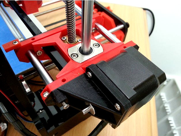
This is a modular Z-Carriage upgrade for the Anet A6-printer. It replaces the stock carriages (those pierced with lots of screws).
The stock carriages don't have a belt tensioner which I consider to be crucial for good quality. I was a bit unsatisfied with the existing upgrades, as I had troubles to get the perfect measures due to warping issues.
The model I developed is 100 % parametric, so everyone can edit measures and tolerances at will.
My priorities were roughly:
perfect distance of the x-rods
perfect fastening of the x-rods
modular design to be able to replace single parts and reduce print time on failure (implicitly supports multi color prints)
reducing the need for supports
ability to upgrade to plain bearings (like Igus)
optics and customizability
Some detail decisions:
The holes for the rods in the braces seem to be oddly shaped: They aren't circles but beveled 8-sided polygons. The rod fits in easier and straight-lined holes can be printed more exactly than curved walls. The polygon is oriented with vertices in each main direction so the rod can be exactly centered without touching the clamp's gap. The polygon is beveled for making the hole not bigger than necessary - some walls are already very thin. Another beveling makes a slight funnel for easier insertion and reducing an elephant's foot which could make the hole too small for the rod.
Some screw holes where you'd expect to have the shapes of hex nut & screw head simply have two hex nut holes. For most of those holes this allows you to decide which way the screw should go in. For others it simply wasn't worth the effort to specialize the screw head hole ;)
Most angles are 45 °. This angle typically can be printed as overhang without any support.
The tensioner knob is rather long. I wanted to provide the longest possible range for tensioning. To get the wheel holder close to the knob I had to bury the knob very deep into the carriage.
I decided to provide my own belt fasteners as the most common ones are rather thick-walled and have sharp edges. Mine can be be customized for your needs, have beveled edges and their measures influence the size of the belt tunnels within the carriages - try to keep them small.
The carriage covers have a grid as bottom layer. This allows to peel them off fairly easy from the bed, but still prevented bending during the print. If you experience any problems with bed adhesion, try to remove the grid or use a raft.
1 Shopping list
Lots of screws! That's the main downside of my design. I tried to mitigate this by allowing to use the screws from the original z-carriages.
All screws are M3 (3 mm thread diameter)
x_rod_brace_clamps: 8 x 14 mm (12 mm minimum, 18 mm possible, if you use the xz_stop, one screw has to be 20 mm as absolute minimum)
x_rod_adjustment: 4 x 12 mm
x_rod_brace to z_carriage: 8 x 10 mm (8 mm minimum, 18 mm possible)
motor screws: 4 x 10 mm (just use the original screws)
z_rod_bearings: 4 x 16 mm (14 mm minimum, just use the original screws)
z_spindle_nut: 8 x 16 mm (just use the original screws)
x_belt_tensioner_knob: the longer, the better (the original 18 mm screws are ok)
x_belt_tensioner (wheel): 16 mm (the original 18 mm should fit, but might touch the back x rod)
z_carriage_cover (optional): 8 x 6 mm (8 mm possible)
hex nuts: 35 (add another one if you want to secure the tensioning screw against turning within the wheel holder; remember to use one lock nut to assure the belt wheel turns freely and the screw cannot get loose)
Also needed: a belt wheel
2 Calibration
First of all you should print right_inner_x_rod_brace and check for the following issues:
The hex nuts should fit in with little to no force
The screws should fit in with little to no force
The clamp should have a small visible gap
The x-rod shall be a tight (but possible) fit. If the clamp's gap is visibly bent open after the rod has been inserted, something is wrong. On the other hand: if the rod isn't held by the clamp at all, that's no better.
If anything is wrong, take a look into the tolerances.scad. The variable _ can be altered to get a better fit. Have a look at https://www.thingiverse.com/thing:2805660 to figure out the perfect values.
3 What to print
Components from left to right (roughly):
left_outer_x_rod_brace: holds the left ends of the x-rods and provides the motor support
left_z_carriage: the core part of the left carriage, connecting the z-rod, z-spindle, x-rod-braces
left_inner_x_rod_brace: holds x-rods and optionally the xz_stop
right_inner_x_rod_brace: holds x-rods, can be used for calibrating the tolerances (see above)
right_z_carriage: the core part of the right carriage, connecting the z-rod, z-spindle, x-rod-braces and the belt tensioner
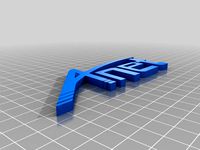
right_outer_x_rod_brace: holds the right ends of the x-rods, has a hole for the tensioner knob and has text on its surface
x_belt_tensioner: holds the right wheel of the x-belt
x_belt_tenioner_knob: contains a hex nut to pull the x_belt_tensioner away from the motor
Optional:
xz_stop: This is necessary when not using a proximity sensor for auto-leveling and when using the original position of the x-stop switch. If you're not sure about this: just print it.
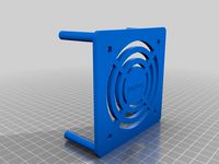
left_z_carriage_cover, right_z_carriage_cover: that's mostly for optics and maybe dust protection
belt_holder (2 x): An alternative to zip ties to fasten the x_belt to the x carriage. They're smaller than the popular ones and can be configured for you needs
4 How to assemble
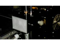
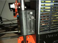
Please have a look at the overview and the photos I made. If anything is unclear, don't hesitate to ask in the comment section and I'll do my best to explain. This section will be updated over time.
5 What's still open/planned
Holder for plain bearings
allow the x-stop-switch to be moved from the x-carriage to the left z-carriage (no good ideas so far)
As with other designs, the right carriage is too light-weighted. The motor on the other side leverages the right z-carriage, when the x-carriage is on the left side. I'm still looking for something useful to weight it down. A spool would be too heavy, maybe a second motor ... ;)
The stock carriages don't have a belt tensioner which I consider to be crucial for good quality. I was a bit unsatisfied with the existing upgrades, as I had troubles to get the perfect measures due to warping issues.
The model I developed is 100 % parametric, so everyone can edit measures and tolerances at will.
My priorities were roughly:
perfect distance of the x-rods
perfect fastening of the x-rods
modular design to be able to replace single parts and reduce print time on failure (implicitly supports multi color prints)
reducing the need for supports
ability to upgrade to plain bearings (like Igus)
optics and customizability
Some detail decisions:
The holes for the rods in the braces seem to be oddly shaped: They aren't circles but beveled 8-sided polygons. The rod fits in easier and straight-lined holes can be printed more exactly than curved walls. The polygon is oriented with vertices in each main direction so the rod can be exactly centered without touching the clamp's gap. The polygon is beveled for making the hole not bigger than necessary - some walls are already very thin. Another beveling makes a slight funnel for easier insertion and reducing an elephant's foot which could make the hole too small for the rod.
Some screw holes where you'd expect to have the shapes of hex nut & screw head simply have two hex nut holes. For most of those holes this allows you to decide which way the screw should go in. For others it simply wasn't worth the effort to specialize the screw head hole ;)
Most angles are 45 °. This angle typically can be printed as overhang without any support.
The tensioner knob is rather long. I wanted to provide the longest possible range for tensioning. To get the wheel holder close to the knob I had to bury the knob very deep into the carriage.
I decided to provide my own belt fasteners as the most common ones are rather thick-walled and have sharp edges. Mine can be be customized for your needs, have beveled edges and their measures influence the size of the belt tunnels within the carriages - try to keep them small.
The carriage covers have a grid as bottom layer. This allows to peel them off fairly easy from the bed, but still prevented bending during the print. If you experience any problems with bed adhesion, try to remove the grid or use a raft.
1 Shopping list
Lots of screws! That's the main downside of my design. I tried to mitigate this by allowing to use the screws from the original z-carriages.
All screws are M3 (3 mm thread diameter)
x_rod_brace_clamps: 8 x 14 mm (12 mm minimum, 18 mm possible, if you use the xz_stop, one screw has to be 20 mm as absolute minimum)
x_rod_adjustment: 4 x 12 mm
x_rod_brace to z_carriage: 8 x 10 mm (8 mm minimum, 18 mm possible)
motor screws: 4 x 10 mm (just use the original screws)
z_rod_bearings: 4 x 16 mm (14 mm minimum, just use the original screws)
z_spindle_nut: 8 x 16 mm (just use the original screws)
x_belt_tensioner_knob: the longer, the better (the original 18 mm screws are ok)
x_belt_tensioner (wheel): 16 mm (the original 18 mm should fit, but might touch the back x rod)
z_carriage_cover (optional): 8 x 6 mm (8 mm possible)
hex nuts: 35 (add another one if you want to secure the tensioning screw against turning within the wheel holder; remember to use one lock nut to assure the belt wheel turns freely and the screw cannot get loose)
Also needed: a belt wheel
2 Calibration
First of all you should print right_inner_x_rod_brace and check for the following issues:
The hex nuts should fit in with little to no force
The screws should fit in with little to no force
The clamp should have a small visible gap
The x-rod shall be a tight (but possible) fit. If the clamp's gap is visibly bent open after the rod has been inserted, something is wrong. On the other hand: if the rod isn't held by the clamp at all, that's no better.
If anything is wrong, take a look into the tolerances.scad. The variable _ can be altered to get a better fit. Have a look at https://www.thingiverse.com/thing:2805660 to figure out the perfect values.
3 What to print
Components from left to right (roughly):
left_outer_x_rod_brace: holds the left ends of the x-rods and provides the motor support
left_z_carriage: the core part of the left carriage, connecting the z-rod, z-spindle, x-rod-braces
left_inner_x_rod_brace: holds x-rods and optionally the xz_stop
right_inner_x_rod_brace: holds x-rods, can be used for calibrating the tolerances (see above)
right_z_carriage: the core part of the right carriage, connecting the z-rod, z-spindle, x-rod-braces and the belt tensioner
right_outer_x_rod_brace: holds the right ends of the x-rods, has a hole for the tensioner knob and has text on its surface
x_belt_tensioner: holds the right wheel of the x-belt
x_belt_tenioner_knob: contains a hex nut to pull the x_belt_tensioner away from the motor
Optional:
xz_stop: This is necessary when not using a proximity sensor for auto-leveling and when using the original position of the x-stop switch. If you're not sure about this: just print it.
left_z_carriage_cover, right_z_carriage_cover: that's mostly for optics and maybe dust protection
belt_holder (2 x): An alternative to zip ties to fasten the x_belt to the x carriage. They're smaller than the popular ones and can be configured for you needs
4 How to assemble
Please have a look at the overview and the photos I made. If anything is unclear, don't hesitate to ask in the comment section and I'll do my best to explain. This section will be updated over time.
5 What's still open/planned
Holder for plain bearings
allow the x-stop-switch to be moved from the x-carriage to the left z-carriage (no good ideas so far)
As with other designs, the right carriage is too light-weighted. The motor on the other side leverages the right z-carriage, when the x-carriage is on the left side. I'm still looking for something useful to weight it down. A spool would be too heavy, maybe a second motor ... ;)
Similar models
thingiverse
free

Anet A6 X Axis Half-slit Carriages by kaa_
...ioner and counterbalance mount (optional).
z-endstop justification
use this simple part to adjust vertical position of z-endstop.
thingiverse
free

FT-5 Z-Link bracket by Pyro_Fox
...ove the z-axis down 1 mm. doing so should lock your z-axis in place and prevent unleveling the bed while you tension the bracket.
thingiverse
free

Flsun i3 x/z axis 70 mm redesign by BoyDrone
...v1.6 version allows for more compliance in the design similar to that of the z axis left and right...
thingiverse
free
A6 X-Belt tensioner "V1-V2" adjustable pressure on Z-axis rods by DaveLado
...the x-axis rods from the z-axis rods by adjusting the screws.
after that, tight the belt of the x-axis after.
have a good print!!
thingiverse
free

x-belt alternative tensioner by GPiotr1
...g m5 screws.
i drew a tensioner with a better grip on the belt.
for screwing you can use an m5 screw with any head and a hex nut.
thingiverse
free
Prusa i3 MK2 X-Idler Tensioner by Jasenk
... kit came with extras that i used.
the pully slide (x-end-idler-front-tensioner) fits one way. if it's tight flip it around.
thingiverse
free

T2.5 Belt tensioner by ceri
...f rod, 4 - 6 mm diameter.
note: you will need to drill 2 4mm holes 20mm apart,for the bolts.
tension and have betterprints !!
thingiverse
free

Anet A6 X-Axis with Anti wobble and tensioner. Now compatible with Manual bed levelling by chekcian
...ezoidal lead screw nuts. however it will also works without these nuts, it just make installation a lot easier and more secured.
thingiverse
free

Anet A8 X Axis Tensioner by FredGenius
...se the two that are currently holding the belt, should be a few more left over from the build).
1x m4x30mm screw.
1x m4 half nut.
thingiverse
free

X Belt holder self locking by nudelpapst
... didn't use a spring as i think it is not necessary.
make sure to have a belt tensioner installed before you use this holder!
Runtimeterror
thingiverse
free

runtimeterror A6 Z-Carriage X Tensioner 5mm Longer by psychrage
...hingiverse
modified runtimeterror's z-carriage x belt tensioner to fit a 20t idler, as i did not have a 16t idler availible.
thingiverse
free

Holes, holes, holes! by runtimeterror
...ow and then.
the example photo shows two prints for 8 mm (7.6 .. 8.4) and 3 mm (2.6 .. 3.4).
the stl file is an example for 3 mm.
thingiverse
free

Profile 4040, 120 mm for Ardumower by runtimeterror
... emc-characteristics for the inductuve perimeter sensor.
the picture shows a 30 mm-version for illustration.
related project page
thingiverse
free

Anet A6 Z-motor scale by runtimeterror
...e. otherwise you won't be able to see the needle above the scale.
can someone please test if this also works for an anet a8?
thingiverse
free

Butterfly (Voronoi, scalable, multilayer) by runtimeterror
...ctly what i had calculated in openscad. maybe a bug due to excessively abusing the csg-functions to improvise missing features ;)
thingiverse
free

Anet A6 PCB Holder (2x MOSFET and Mainboard) by runtimeterror
...r not hitting your print - don't make them too long for not hitting your mainboard's back!!!)
as many zipties as you like
thingiverse
free

Cut Kobayashi Fidget Cube (Infinity Cube, parametric)
...thingiverse i used the fine kobayashi fidget cube from runtimeterror to get one with a different surface. so i...
thingiverse
free

Twig Mobile Holder (ceiling mount) by runtimeterror
... break.
i'm fairly new to 3d-printing and this is my first thing designed by myself. i'd be happy to get some feedback :)
thingiverse
free

Kobayashi Fidget Cube (Infinity Cube, parametric) by runtimeterror
...ot of time in making his cube as printable as possible. he also provides lots of printing tips and solutions to typical pitfalls.
A6
3ddd
free

audi a6
...audi a6
3ddd
audi a6
audi a6
3ddd
$1

AUDI A6
...audi a6
3ddd
audi
audi a6, — семейство легковых автомобилей бизнес-класса, выпускающихся под маркой audi
3ddd
$1

Slipper Bath A6
...slipper bath a6
3ddd
toto
slipper bath a6
3ddd
$1

Slipper Bath A6
...slipper bath a6
3ddd
toto , ванна
slipper bath a6
3d_export
$40

Audi A6 3D Model
...audi a6 3d model
3dexport
audi a6
audi a6 3d model kaxa3d 8037 3dexport
3d_export
$79

Audi A6 3D Model
...audi a6 3d model
3dexport
audi auto a6
audi a6 3d model growl 3313 3dexport
3d_export
$40

Audi a6 3D Model
...audi a6 3d model
3dexport
car audi a6
audi a6 3d model bararhakopre20 91055 3dexport
turbosquid
$99

Audi A6
... available on turbo squid, the world's leading provider of digital 3d models for visualization, films, television, and games.
turbosquid
$99

Audi A6
... available on turbo squid, the world's leading provider of digital 3d models for visualization, films, television, and games.
turbosquid
$90

Audi A6
... available on turbo squid, the world's leading provider of digital 3d models for visualization, films, television, and games.
Anet
thingiverse
free

Anet by derbodesign
...anet by derbodesign
thingiverse
logo anet
thingiverse
free
Anet e10 , Anet v1.0 by jonathan_943D
...anet e10 , anet v1.0 by jonathan_943d
thingiverse
soporte de ventilador de 80mm, para controladora anet v1.0
thingiverse
free
Anet A8 Anet AM8 Y belt holder
...anet a8 anet am8 y belt holder
thingiverse
anet a8 anet am8 y belt holder
thingiverse
free
Anet A8 Probe Bracket for anet sensor by chelrix
...anet a8 probe bracket for anet sensor by chelrix
thingiverse
anet a8 probe bracket for anet official sensor and marlin firmware
thingiverse
free

Anet logo by JUST3D_PRNTNG
...anet logo by just3d_prntng
thingiverse
anet logo
thingiverse
free
Fan nozzle for Anet A8 with original Anet levelsensor by peteruhlmann
...et levelsensor by peteruhlmann
thingiverse
here is an improved fan nozzle for the anet a8 with original level sensor from anet.
thingiverse
free
Anet Et4 Box
...anet et4 box
thingiverse
tool box for anet et4
thingiverse
free
Anet Logo by Superflex_Plastic_Fantastic
...anet logo by superflex_plastic_fantastic
thingiverse
anet logo to incorporate into designs.
thingiverse
free
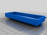
Box for Anet ET4
...box for anet et4
thingiverse
this is a simple box for tool of anet et4
thingiverse
free

Anet V1.0 Board Kühlung (80mm Lüfter) / Anet A8 by MadCre8
...anet v1.0 board kühlung (80mm lüfter) / anet a8 by madcre8
thingiverse
anet v1.0 board kühlung (80mm lüfter) / anet a8
Carriage
archibase_planet
free
Carriage
...arriage
archibase planet
perambulator baby carriage pram
carriage n250908 - 3d model (*.gsm+*.3ds) for interior 3d visualization.
3d_export
free
carriage
...carriage
3dexport
old fashion carriage model, more files here:
turbosquid
$140

Carriage
...urbosquid
royalty free 3d model carriage for download as max on turbosquid: 3d models for games, architecture, videos. (1482052)
turbosquid
$25
Carriage
...urbosquid
royalty free 3d model carriage for download as max on turbosquid: 3d models for games, architecture, videos. (1285944)
3d_export
free
carriage
...carriage
3dexport
game cart
3d_ocean
$15
Barrel Carriage
...ieval oak old transport wheels wine wood
this model contains a barrel and a carriage. it is a medieval type of wood oak carriage.
turbosquid
$40
Carriage
...ty free 3d model carriage for download as obj, fbx, and blend on turbosquid: 3d models for games, architecture, videos. (1290094)
turbosquid
free

Carriage
...yalty free 3d model carriage for download as ma, obj, and fbx on turbosquid: 3d models for games, architecture, videos. (1239157)
3d_export
$5
Medieval carriage
...medieval carriage
3dexport
medieval carriage in fairy style
turbosquid
$58

Carriage
...d model carriage with scene for download as max, obj, and fbx on turbosquid: 3d models for games, architecture, videos. (1276262)
Parametric
turbosquid
$25

Parametric
...oyalty free 3d model parametric for download as blend and stl on turbosquid: 3d models for games, architecture, videos. (1683196)
3ddd
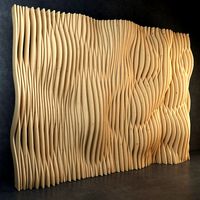
$1
Parametric Wall
...parametric wall
3ddd
панель
parametric wall with shelf
3d_export
$5
parametric table
...parametric table
3dexport
parametric table model created on rhinoceros 6. this 3d model includes: .gh, .3dm files
turbosquid
$2
parametrical chandelier
...lty free 3d model parametrical chandelier for download as dxf on turbosquid: 3d models for games, architecture, videos. (1257635)
turbosquid
$2
Parametric Seat
...id
royalty free 3d model parametric seat for download as max on turbosquid: 3d models for games, architecture, videos. (1691557)
turbosquid
$2
Parametric Wall
...id
royalty free 3d model parametric wall for download as max on turbosquid: 3d models for games, architecture, videos. (1690373)
turbosquid
$1
Parametric Wall
...id
royalty free 3d model parametric wall for download as max on turbosquid: 3d models for games, architecture, videos. (1691303)
turbosquid
$1
Parametric Wall
...id
royalty free 3d model parametric wall for download as max on turbosquid: 3d models for games, architecture, videos. (1691148)
turbosquid
$19

Parametric Bench
...ty free 3d model parametric bench for download as max and max on turbosquid: 3d models for games, architecture, videos. (1713396)
turbosquid
free
Parametric wall
...ee 3d model parametric wall for download as max, obj, and fbx on turbosquid: 3d models for games, architecture, videos. (1356869)
Modular
3ddd
$1
MODULAR
...modular
3ddd
modular , врезной свет
modular потолочные светильники
3ddd
$1
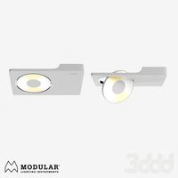
Modular Spock
...modular spock
3ddd
modular
modular spock
3ddd
$1
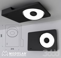
MODULAR / Spock
...modular / spock
3ddd
modular
modular/spock
design_connected
$7

Modular
...modular
designconnected
emmemobili modular shelves and storage computer generated 3d model. designed by ferruccio laviani.
3ddd
$1
Modular spock
...modular spock
3ddd
modular
spock wall led
turbosquid
$25
Modular sofa Angelo Cappellini Modular
...a angelo cappellini modular for download as max, fbx, and obj on turbosquid: 3d models for games, architecture, videos. (1570923)
turbosquid
$15

Modular sofa Angelo Cappellini Modular
...a angelo cappellini modular for download as max, fbx, and obj on turbosquid: 3d models for games, architecture, videos. (1570304)
3ddd
$1
Modular 2FLAT2C
...modular 2flat2c
3ddd
modular
modularhttp://www.supermodular.com/
3d_export
free
Modular walls
...modular walls
3dexport
modular walls for playing without materials and textures
3ddd
$1
Modular / Lighting Juliette
...modular / lighting juliette
3ddd
modular
modular lighting juliette
Z
3d_export
$5
nissan z
...nissan z
3dexport
nissan z
3ddd
$1

Vase Z
...vase z
3ddd
vase z
3ddd
$1
полотенцесушить Z
...полотенцесушить z
3ddd
полотенцесушитель
полотенцесушить z
design_connected
free
Z-Chair
...z-chair
designconnected
free 3d model of z-chair designed by karman, aleksei.
design_connected
$11
Z Lamp
...z lamp
designconnected
phillips z lamp computer generated 3d model. designed by kalff, louis.
3d_export
$5
Dragon balls z
...dragon balls z
3dexport
dragon ball z
turbosquid
$20

Fighter Z
...
turbosquid
royalty free 3d model fighter z for download as on turbosquid: 3d models for games, architecture, videos. (1292563)
turbosquid
$9

Pen Z
...pen z
turbosquid
free 3d model pen z for download as obj on turbosquid: 3d models for games, architecture, videos. (1686775)
turbosquid
free
z chair
...z chair
turbosquid
free 3d model z chair for download as max on turbosquid: 3d models for games, architecture, videos. (1410230)
turbosquid
$5

Letter Z
...urbosquid
royalty free 3d model letter z for download as max on turbosquid: 3d models for games, architecture, videos. (1408540)