Thingiverse
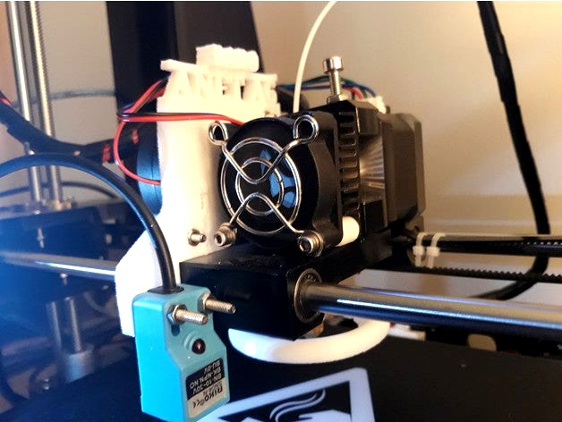
Anet A6 - Autolevel bed sensor Blue SN-04N by d3adlydozen
by Thingiverse
Last crawled date: 3 years ago
Anet A6 - Autolevel bed sensor Blue SN-04N with configuration.h Marlin 1.18:
easy way to the went screw
more space to adjust the sensor
configuration.h Marlin 1.18 (more function = less memory)
/**
Marlin 3D Printer Firmware
Copyright (C) 2016 MarlinFirmware [https://github.com/MarlinFirmware/Marlin]
Based on Sprinter and grbl.
Copyright (C) 2011 Camiel Gubbels / Erik van der Zalm
This program is free software: you can redistribute it and/or modify
it under the terms of the GNU General Public License as published by
the Free Software Foundation, either version 3 of the License, or
(at your option) any later version.
This program is distributed in the hope that it will be useful,
but WITHOUT ANY WARRANTY; without even the implied warranty of
MERCHANTABILITY or FITNESS FOR A PARTICULAR PURPOSE. See the
GNU General Public License for more details.
You should have received a copy of the GNU General Public License
along with this program. If not, see http://www.gnu.org/licenses/.
*/
/**
Configuration.h
Basic settings such as:
Type of electronics
Type of temperature sensor
Printer geometry
Endstop configuration
LCD controller
Extra features
Advanced settings can be found in Configuration_adv.h
*/
ifndef CONFIGURATION_H
define CONFIGURATION_H
define CONFIGURATION_H_VERSION 010107
//===========================================================================
//============================= Getting Started =============================
//===========================================================================
/**
Here are some standard links for getting your machine calibrated:
http://reprap.org/wiki/Calibration
https://www.youtube.com/watch?v=hLKs8mZJMPM
https://sites.google.com/site/repraplogphase/calibration-of-your-reprap
https://www.thingiverse.com/thing:2483067
*/
//===========================================================================
//============================= DELTA Printer ===============================
//===========================================================================
// For a Delta printer start with one of the configuration files in the
// example_configurations/delta directory and customize for your machine.
//
//===========================================================================
//============================= SCARA Printer ===============================
//===========================================================================
// For a SCARA printer start with the configuration files in
// example_configurations/SCARA and customize for your machine.
//
// @section info
// User-specified version info of this build to display in [Pronterface, etc] terminal window during
// startup. Implementation of an idea by Prof Braino to inform user that any changes made to this
// build by the user have been successfully uploaded into firmware.
define STRING_CONFIG_H_AUTHOR "(Ralf_E, ANET A6 config)" // Who made the changes.
define SHOW_BOOTSCREEN
define STRING_SPLASH_LINE1 SHORT_BUILD_VERSION // will be shown during bootup in line 1
define STRING_SPLASH_LINE2 WEBSITE_URL // will be shown during bootup in line 2
//
// * VENDORS PLEASE READ ****
//
// Marlin now allow you to have a vendor boot image to be displayed on machine
// start. When SHOW_CUSTOM_BOOTSCREEN is defined Marlin will first show your
// custom boot image and then the default Marlin boot image is shown.
//
// We suggest for you to take advantage of this new feature and keep the Marlin
// boot image unmodified. For an example have a look at the bq Hephestos 2
// example configuration folder.
//
//#define SHOW_CUSTOM_BOOTSCREEN
// @section machine
/**
Select which serial port on the board will be used for communication with the host.
This allows the connection of wireless adapters (for instance) to non-default port pins.
Serial port 0 is always used by the Arduino bootloader regardless of this setting.
:[0, 1, 2, 3, 4, 5, 6, 7]
*/
define SERIAL_PORT 0
/**
This setting determines the communication speed of the printer.
250000 works in most cases, but you might try a lower speed if
you commonly experience drop-outs during host printing.
You may try up to 1000000 to speed up SD file transfer.
:[2400, 9600, 19200, 38400, 57600, 115200, 250000, 500000, 1000000]
*/
define BAUDRATE 115200
// Enable the Bluetooth serial interface on AT90USB devices
//#define BLUETOOTH
// The following define selects which electronics board you have.
// Please choose the name from boards.h that matches your setup
ifndef MOTHERBOARD
define MOTHERBOARD BOARD_ANET_10
endif
// Optional custom name for your RepStrap or other custom machine
// Displayed in the LCD "Ready" message
//#define CUSTOM_MACHINE_NAME "3D Printer"
// Define this to set a unique identifier for this printer, (Used by some programs to differentiate between machines)
// You can use an online service to generate a random UUID. (eg http://www.uuidgenerator.net/version4)
//#define MACHINE_UUID "00000000-0000-0000-0000-000000000000"
// @section extruder
// This defines the number of extruders
// :[1, 2, 3, 4, 5]
define EXTRUDERS 1
// Generally expected filament diameter (1.75, 2.85, 3.0, ...). Used for Volumetric, Filament Width Sensor, etc.
define DEFAULT_NOMINAL_FILAMENT_DIA 1.75
// For Cyclops or any "multi-extruder" that shares a single nozzle.
//#define SINGLENOZZLE
/**
Průša MK2 Single Nozzle Multi-Material Multiplexer, and variants.
This device allows one stepper driver on a control board to drive
two to eight stepper motors, one at a time, in a manner suitable
for extruders.
This option only allows the multiplexer to switch on tool-change.
Additional options to configure custom E moves are pending.
*/
//#define MK2_MULTIPLEXER
if ENABLED(MK2_MULTIPLEXER)
// Override the default DIO selector pins here, if needed.
// Some pins files may provide defaults for these pins.
//#define E_MUX0_PIN 40 // Always Required
//#define E_MUX1_PIN 42 // Needed for 3 to 8 steppers
//#define E_MUX2_PIN 44 // Needed for 5 to 8 steppers
endif
// A dual extruder that uses a single stepper motor
//#define SWITCHING_EXTRUDER
if ENABLED(SWITCHING_EXTRUDER)
define SWITCHING_EXTRUDER_SERVO_NR 0
define SWITCHING_EXTRUDER_SERVO_ANGLES { 0, 90 } // Angles for E0, E1[, E2, E3]
if EXTRUDERS > 3
#define SWITCHING_EXTRUDER_E23_SERVO_NR 1
endif
endif
// A dual-nozzle that uses a servomotor to raise/lower one of the nozzles
//#define SWITCHING_NOZZLE
if ENABLED(SWITCHING_NOZZLE)
define SWITCHING_NOZZLE_SERVO_NR 0
define SWITCHING_NOZZLE_SERVO_ANGLES { 0, 90 } // Angles for E0, E1
//#define HOTEND_OFFSET_Z { 0.0, 0.0 }
endif
/**
Two separate X-carriages with extruders that connect to a moving part
via a magnetic docking mechanism. Requires SOL1_PIN and SOL2_PIN.
*/
//#define PARKING_EXTRUDER
if ENABLED(PARKING_EXTRUDER)
define PARKING_EXTRUDER_SOLENOIDS_INVERT // If enabled, the solenoid is NOT magnetized with applied voltage
define PARKING_EXTRUDER_SOLENOIDS_PINS_ACTIVE LOW // LOW or HIGH pin signal energizes the coil
define PARKING_EXTRUDER_SOLENOIDS_DELAY 250 // Delay (ms) for magnetic field. No delay if 0 or not defined.
define PARKING_EXTRUDER_PARKING_X { -78, 184 } // X positions for parking the extruders
define PARKING_EXTRUDER_GRAB_DISTANCE 1 // mm to move beyond the parking point to grab the extruder
define PARKING_EXTRUDER_SECURITY_RAISE 5 // Z-raise before parking
define HOTEND_OFFSET_Z { 0.0, 1.3 } // Z-offsets of the two hotends. The first must be 0.
endif
/**
"Mixing Extruder"
Adds a new code, M165, to set the current mix factors.
Extends the stepping routines to move multiple steppers in proportion to the mix.
Optional support for Repetier Firmware M163, M164, and virtual extruder.
This implementation supports only a single extruder.
Enable DIRECT_MIXING_IN_G1 for Pia Taubert's reference implementation
*/
//#define MIXING_EXTRUDER
if ENABLED(MIXING_EXTRUDER)
define MIXING_STEPPERS 2 // Number of steppers in your mixing extruder
define MIXING_VIRTUAL_TOOLS 16 // Use the Virtual Tool method with M163 and M164
//#define DIRECT_MIXING_IN_G1 // Allow ABCDHI mix factors in G1 movement commands
endif
// Offset of the extruders (uncomment if using more than one and relying on firmware to position when changing).
// The offset has to be X=0, Y=0 for the extruder 0 hotend (default extruder).
// For the other hotends it is their distance from the extruder 0 hotend.
//#define HOTEND_OFFSET_X {0.0, 20.00} // (in mm) for each extruder, offset of the hotend on the X axis
//#define HOTEND_OFFSET_Y {0.0, 5.00} // (in mm) for each extruder, offset of the hotend on the Y axis
// @section machine
/**
Select your power supply here. Use 0 if you haven't connected the PS_ON_PIN
0 = No Power Switch
1 = ATX
2 = X-Box 360 203Watts (the blue wire connected to PS_ON and the red wire to VCC)
:{ 0:'No power switch', 1:'ATX', 2:'X-Box 360' }
*/
define POWER_SUPPLY 0
if POWER_SUPPLY > 0
// Enable this option to leave the PSU off at startup.
// Power to steppers and heaters will need to be turned on with M80.
//#define PS_DEFAULT_OFF
endif
// @section temperature
//===========================================================================
//============================= Thermal Settings ============================
//===========================================================================
/**
--NORMAL IS 4.7kohm PULLUP!-- 1kohm pullup can be used on hotend sensor, using correct resistor and table
Temperature sensors available:
-3 : thermocouple with MAX31855 (only for sensor 0)
-2 : thermocouple with MAX6675 (only for sensor 0)
-1 : thermocouple with AD595
0 : not used
1 : 100k thermistor - best choice for EPCOS 100k (4.7k pullup)
2 : 200k thermistor - ATC Semitec 204GT-2 (4.7k pullup)
3 : Mendel-parts thermistor (4.7k pullup)
4 : 10k thermistor !! do not use it for a hotend. It gives bad resolution at high temp. !!
5 : 100K thermistor - ATC Semitec 104GT-2 (Used in ParCan & J-Head) (4.7k pullup)
6 : 100k EPCOS - Not as accurate as table 1 (created using a fluke thermocouple) (4.7k pullup)
7 : 100k Honeywell thermistor 135-104LAG-J01 (4.7k pullup)
71 : 100k Honeywell thermistor 135-104LAF-J01 (4.7k pullup)
8 : 100k 0603 SMD Vishay NTCS0603E3104FXT (4.7k pullup)
9 : 100k GE Sensing AL03006-58.2K-97-G1 (4.7k pullup)
10 : 100k RS thermistor 198-961 (4.7k pullup)
11 : 100k beta 3950 1% thermistor (4.7k pullup)
12 : 100k 0603 SMD Vishay NTCS0603E3104FXT (4.7k pullup) (calibrated for Makibox hot bed)
13 : 100k Hisens 3950 1% up to 300°C for hotend "Simple ONE " & "Hotend "All In ONE"
20 : the PT100 circuit found in the Ultimainboard V2.x
60 : 100k Maker's Tool Works Kapton Bed Thermistor beta=3950
66 : 4.7M High Temperature thermistor from Dyze Design
70 : the 100K thermistor found in the bq Hephestos 2
75 : 100k Generic Silicon Heat Pad with NTC 100K MGB18-104F39050L32 thermistor
1k ohm pullup tables - This is atypical, and requires changing out the 4.7k pullup for 1k.
(but gives greater accuracy and more stable PID)
51 : 100k thermistor - EPCOS (1k pullup)
52 : 200k thermistor - ATC Semitec 204GT-2 (1k pullup)
55 : 100k thermistor - ATC Semitec 104GT-2 (Used in ParCan & J-Head) (1k pullup)
1047 : Pt1000 with 4k7 pullup
1010 : Pt1000 with 1k pullup (non standard)
147 : Pt100 with 4k7 pullup
110 : Pt100 with 1k pullup (non standard)
Use these for Testing or Development purposes. NEVER for production machine.
998 : Dummy Table that ALWAYS reads 25°C or the temperature defined below.
999 : Dummy Table that ALWAYS reads 100°C or the temperature defined below.
:{ '0': "Not used", '1':"100k / 4.7k - EPCOS", '2':"200k / 4.7k - ATC Semitec 204GT-2", '3':"Mendel-parts / 4.7k", '4':"10k !! do not use for a hotend. Bad resolution at high temp. !!", '5':"100K / 4.7k - ATC Semitec 104GT-2 (Used in ParCan & J-Head)", '6':"100k / 4.7k EPCOS - Not as accurate as Table 1", '7':"100k / 4.7k Honeywell 135-104LAG-J01", '8':"100k / 4.7k 0603 SMD Vishay NTCS0603E3104FXT", '9':"100k / 4.7k GE Sensing AL03006-58.2K-97-G1", '10':"100k / 4.7k RS 198-961", '11':"100k / 4.7k beta 3950 1%", '12':"100k / 4.7k 0603 SMD Vishay NTCS0603E3104FXT (calibrated for Makibox hot bed)", '13':"100k Hisens 3950 1% up to 300°C for hotend 'Simple ONE ' & hotend 'All In ONE'", '20':"PT100 (Ultimainboard V2.x)", '51':"100k / 1k - EPCOS", '52':"200k / 1k - ATC Semitec 204GT-2", '55':"100k / 1k - ATC Semitec 104GT-2 (Used in ParCan & J-Head)", '60':"100k Maker's Tool Works Kapton Bed Thermistor beta=3950", '66':"Dyze Design 4.7M High Temperature thermistor", '70':"the 100K thermistor found in the bq Hephestos 2", '71':"100k / 4.7k Honeywell 135-104LAF-J01", '147':"Pt100 / 4.7k", '1047':"Pt1000 / 4.7k", '110':"Pt100 / 1k (non-standard)", '1010':"Pt1000 / 1k (non standard)", '-3':"Thermocouple + MAX31855 (only for sensor 0)", '-2':"Thermocouple + MAX6675 (only for sensor 0)", '-1':"Thermocouple + AD595",'998':"Dummy 1", '999':"Dummy 2" }
*/
define TEMP_SENSOR_0 5
define TEMP_SENSOR_1 0
define TEMP_SENSOR_2 0
define TEMP_SENSOR_3 0
define TEMP_SENSOR_4 0
define TEMP_SENSOR_BED 5
// Dummy thermistor constant temperature readings, for use with 998 and 999
define DUMMY_THERMISTOR_998_VALUE 25
define DUMMY_THERMISTOR_999_VALUE 100
// Use temp sensor 1 as a redundant sensor with sensor 0. If the readings
// from the two sensors differ too much the print will be aborted.
//#define TEMP_SENSOR_1_AS_REDUNDANT
define MAX_REDUNDANT_TEMP_SENSOR_DIFF 10
// Extruder temperature must be close to target for this long before M109 returns success
define TEMP_RESIDENCY_TIME 10 // (seconds)
define TEMP_HYSTERESIS 3 // (degC) range of +/- temperatures considered "close" to the target one
define TEMP_WINDOW 1 // (degC) Window around target to start the residency timer x degC early.
//-----------------DODANE-----
// Extruder temperature must be close to target for this long before M109 returns success
//#define TEMP_RESIDENCY_TIME 6 // (seconds)
//#define TEMP_HYSTERESIS 3 // (degC) range of +/- temperatures considered "close" to the target one
//#define TEMP_WINDOW 1 // (degC) Window around target to start the residency timer x degC early.
//-----------------DODANE----
// Bed temperature must be close to target for this long before M190 returns success
define TEMP_BED_RESIDENCY_TIME 10 // (seconds)
define TEMP_BED_HYSTERESIS 3 // (degC) range of +/- temperatures considered "close" to the target one
define TEMP_BED_WINDOW 1 // (degC) Window around target to start the residency timer x degC early.
//-----------------DODANE------
// Bed temperature must be close to target for this long before M190 returns success
//#define TEMP_BED_RESIDENCY_TIME 6 // (seconds)
//#define TEMP_BED_HYSTERESIS 3 // (degC) range of +/- temperatures considered "close" to the target one
//#define TEMP_BED_WINDOW 1 // (degC) Window around target to start the residency timer x degC early.
//-----------------DODANE------
// The minimal temperature defines the temperature below which the heater will not be enabled It is used
// to check that the wiring to the thermistor is not broken.
// Otherwise this would lead to the heater being powered on all the time.
define HEATER_0_MINTEMP 5
define HEATER_1_MINTEMP 5
define HEATER_2_MINTEMP 5
define HEATER_3_MINTEMP 5
define HEATER_4_MINTEMP 5
define BED_MINTEMP 5
// When temperature exceeds max temp, your heater will be switched off.
// This feature exists to protect your hotend from overheating accidentally, but NOT from thermistor short/failure!
// You should use MINTEMP for thermistor short/failure protection.
define HEATER_0_MAXTEMP 275
define HEATER_1_MAXTEMP 275
define HEATER_2_MAXTEMP 275
define HEATER_3_MAXTEMP 275
define HEATER_4_MAXTEMP 275
define BED_MAXTEMP 130
//===========================================================================
//============================= PID Settings ================================
//===========================================================================
// PID Tuning Guide here: http://reprap.org/wiki/PID_Tuning
// Comment the following line to disable PID and enable bang-bang.
define PIDTEMP
define BANG_MAX 255 // Limits current to nozzle while in bang-bang mode; 255=full current
define PID_MAX BANG_MAX // Limits current to nozzle while PID is active (see PID_FUNCTIONAL_RANGE below); 255=full current
define PID_K1 0.95 // Smoothing factor within the PID
if ENABLED(PIDTEMP)
//#define PID_AUTOTUNE_MENU // Add PID Autotune to the LCD "Temperature" menu to run M303 and apply the result.
//#define PID_DEBUG // Sends debug data to the serial port.
//#define PID_OPENLOOP 1 // Puts PID in open loop. M104/M140 sets the output power from 0 to PID_MAX
//#define SLOW_PWM_HEATERS // PWM with very low frequency (roughly 0.125Hz=8s) and minimum state time of approximately 1s useful for heaters driven by a relay
//#define PID_PARAMS_PER_HOTEND // Uses separate PID parameters for each extruder (useful for mismatched extruders)
// Set/get with gcode: M301 E[extruder number, 0-2]
define PID_FUNCTIONAL_RANGE 10 // If the temperature difference between the target temperature and the actual temperature
// is more than PID_FUNCTIONAL_RANGE then the PID will be shut off and the heater will be set to min/max.
// If you are using a pre-configured hotend then you can use one of the value sets by uncommenting it
// Ultimaker
//#define DEFAULT_Kp 22.2
//#define DEFAULT_Ki 1.08
//#define DEFAULT_Kd 114
// MakerGear
//#define DEFAULT_Kp 7.0
//#define DEFAULT_Ki 0.1
//#define DEFAULT_Kd 12
// Mendel Parts V9 on 12V
//#define DEFAULT_Kp 63.0
//#define DEFAULT_Ki 2.25
//#define DEFAULT_Kd 440
// ANET A6 Firmware V2.0 Standard Extruder defaults:
// PID-P: +022.20, PID-I: +001.08, PID-D: +114.00, PID-C: 1
//#define DEFAULT_Kp 22.2
//#define DEFAULT_Ki 1.08
//#define DEFAULT_Kd 114.0
// --------------DOPISAŁEM ----
// ANET A8 Standard Extruder at 210 Degree Celsius and 100% Fan
//(measured after M106 S255 with M303 E0 S210 C8)
//#define DEFAULT_Kp 21.0
//#define DEFAULT_Ki 1.25
//#define DEFAULT_Kd 86.0
// --------------DOPISAŁEM -----
// Tuned by ralf-e. Always re-tune for your machine!
define DEFAULT_Kp 16.83
define DEFAULT_Ki 1.02
define DEFAULT_Kd 69.29
endif // PIDTEMP
//===========================================================================
//============================= PID > Bed Temperature Control ===============
//===========================================================================
// Select PID or bang-bang with PIDTEMPBED. If bang-bang, BED_LIMIT_SWITCHING will enable hysteresis
//
// Uncomment this to enable PID on the bed. It uses the same frequency PWM as the extruder.
// If your PID_dT is the default, and correct for your hardware/configuration, that means 7.689Hz,
// which is fine for driving a square wave into a resistive load and does not significantly impact you FET heating.
// This also works fine on a Fotek SSR-10DA Solid State Relay into a 250W heater.
// If your configuration is significantly different than this and you don't understand the issues involved, you probably
// shouldn't use bed PID until someone else verifies your hardware works.
// If this is enabled, find your own PID constants below.
define PIDTEMPBED
//#define BED_LIMIT_SWITCHING
// This sets the max power delivered to the bed, and replaces the HEATER_BED_DUTY_CYCLE_DIVIDER option.
// all forms of bed control obey this (PID, bang-bang, bang-bang with hysteresis)
// setting this to anything other than 255 enables a form of PWM to the bed just like HEATER_BED_DUTY_CYCLE_DIVIDER did,
// so you shouldn't use it unless you are OK with PWM on your bed. (see the comment on enabling PIDTEMPBED)
define MAX_BED_POWER 255 // limits duty cycle to bed; 255=full current
if ENABLED(PIDTEMPBED)
//#define PID_BED_DEBUG // Sends debug data to the serial port.
//120V 250W silicone heater into 4mm borosilicate (MendelMax 1.5+)
//from FOPDT model - kp=.39 Tp=405 Tdead=66, Tc set to 79.2, aggressive factor of .15 (vs .1, 1, 10)
//#define DEFAULT_bedKp 10.00
//#define DEFAULT_bedKi .023
//#define DEFAULT_bedKd 305.4
//120V 250W silicone heater into 4mm borosilicate (MendelMax 1.5+)
//from pidautotune
//#define DEFAULT_bedKp 97.1
//#define DEFAULT_bedKi 1.41
//#define DEFAULT_bedKd 1675.16
// ANET A6
// original Bed + 0.3mm Heat conducting into 4mm borosilicate (PID-Autotune: M303 E-1 S60 C5):
//#define DEFAULT_bedKp 295.00
//#define DEFAULT_bedKi 35.65
//#define DEFAULT_bedKd 610.21
define DEFAULT_bedKp 295.00
define DEFAULT_bedKi 35.65
define DEFAULT_bedKd 610.21
// FIND YOUR OWN: "M303 E-1 C8 S90" to run autotune on the bed at 90 degreesC for 8 cycles.
endif // PIDTEMPBED
// @section extruder
// This option prevents extrusion if the temperature is below EXTRUDE_MINTEMP.
// It also enables the M302 command to set the minimum extrusion temperature
// or to allow moving the extruder regardless of the hotend temperature.
// IT IS HIGHLY RECOMMENDED TO LEAVE THIS OPTION ENABLED!
define PREVENT_COLD_EXTRUSION
define EXTRUDE_MINTEMP 170
// This option prevents a single extrusion longer than EXTRUDE_MAXLENGTH.
// Note that for Bowden Extruders a too-small value here may prevent loading.
define PREVENT_LENGTHY_EXTRUDE
define EXTRUDE_MAXLENGTH 200
//===========================================================================
//======================== Thermal Runaway Protection =======================
//===========================================================================
/**
Thermal Protection provides additional protection to your printer from damage
and fire. Marlin always includes safe min and max temperature ranges which
protect against a broken or disconnected thermistor wire.
The issue: If a thermistor falls out, it will report the much lower
temperature of the air in the room, and the the firmware will keep
the heater on.
If you get "Thermal Runaway" or "Heating failed" errors the
details can be tuned in Configuration_adv.h
*/
define THERMAL_PROTECTION_HOTENDS // Enable thermal protection for all extruders
define THERMAL_PROTECTION_BED // Enable thermal protection for the heated bed
//===========================================================================
//============================= Mechanical Settings =========================
//===========================================================================
// @section machine
// Uncomment one of these options to enable CoreXY, CoreXZ, or CoreYZ kinematics
// either in the usual order or reversed
//#define COREXY
//#define COREXZ
//#define COREYZ
//#define COREYX
//#define COREZX
//#define COREZY
//===========================================================================
//============================== Endstop Settings ===========================
//===========================================================================
// @section homing
// Specify here all the endstop connectors that are connected to any endstop or probe.
// Almost all printers will be using one per axis. Probes will use one or more of the
// extra connectors. Leave undefined any used for non-endstop and non-probe purposes.
define USE_XMIN_PLUG
define USE_YMIN_PLUG
define USE_ZMIN_PLUG
//#define USE_XMAX_PLUG
//#define USE_YMAX_PLUG
//#define USE_ZMAX_PLUG
// coarse Endstop Settings
define ENDSTOPPULLUPS // Comment this out (using // at the start of the line) to disable the endstop pullup resistors
if DISABLED(ENDSTOPPULLUPS)
// fine endstop settings: Individual pullups. will be ignored if ENDSTOPPULLUPS is defined
//#define ENDSTOPPULLUP_XMAX
//#define ENDSTOPPULLUP_YMAX
//#define ENDSTOPPULLUP_ZMAX
//#define ENDSTOPPULLUP_XMIN
//#define ENDSTOPPULLUP_YMIN
//#define ENDSTOPPULLUP_ZMIN
//#define ENDSTOPPULLUP_ZMIN_PROBE
endif
// Mechanical endstop with COM to ground and NC to Signal uses "false" here (most common setup).
define X_MIN_ENDSTOP_INVERTING true // set to true to invert the logic of the endstop.
define Y_MIN_ENDSTOP_INVERTING true // set to true to invert the logic of the endstop.
define Z_MIN_ENDSTOP_INVERTING true // set to true to invert the logic of the endstop. set to true for SN-04N False for TL-W3M.
define X_MAX_ENDSTOP_INVERTING true // set to true to invert the logic of the endstop.
define Y_MAX_ENDSTOP_INVERTING true // set to true to invert the logic of the endstop. -GYLO FALSE
define Z_MAX_ENDSTOP_INVERTING true // set to true to invert the logic of the endstop. -GYLO FALSE
// wlaczyc trzeba dla bed autolevel-------------------------
define Z_MIN_PROBE_ENDSTOP_INVERTING true // set to true to invert the logic of the probe.set to same logic as "Z_MIN_ENDSTOP_INVERTING". -GYLO FALSE
// Enable this feature if all enabled endstop pins are interrupt-capable.
// This will remove the need to poll the interrupt pins, saving many CPU cycles.
define ENDSTOP_INTERRUPTS_FEATURE
//=============================================================================
//============================== Movement Settings ============================
//=============================================================================
// @section motion
/**
Default Settings
These settings can be reset by M502
Note that if EEPROM is enabled, saved values will override these.
*/
/**
With this option each E stepper can have its own factors for the
following movement settings. If fewer factors are given than the
total number of extruders, the last value applies to the rest.
*/
//#define DISTINCT_E_FACTORS
/**
Default Axis Steps Per Unit (steps/mm)
Override with M92
X, Y, Z, E0 [, E1[, E2[, E3[, E4]]]]
*/
//#define DEFAULT_AXIS_STEPS_PER_UNIT { 80, 80, 4000, 500 }
// ANET A6 Firmwae V2.0 defaults: (steps/mm)
// Xsteps/mm: +100.0, Ysteps/mm: +100.0, Zsteps/mm: +0400.0, eSteps/mm: +0095.0
define DEFAULT_AXIS_STEPS_PER_UNIT {100, 100, 400, 95}
//#define DEFAULT_AXIS_STEPS_PER_UNIT {80, 80, 400, 95}
/**
Default Max Feed Rate (mm/s)
Override with M203
X, Y, Z, E0 [, E1[, E2[, E3[, E4]]]]
*/
//#define DEFAULT_MAX_FEEDRATE { 300, 300, 5, 25 }
// ANET A6 Firmware V2.0 defaults (Vmax):
// Vmax x: 400, Vmax y: 400, Vmax z: 4, Vmax e: 25
define DEFAULT_MAX_FEEDRATE {400, 400, 4, 25}
//#define DEFAULT_MAX_FEEDRATE {400, 400, 20, 50}
/**
Default Max Acceleration (change/s) change = mm/s
(Maximum start speed for accelerated moves)
Override with M201
X, Y, Z, E0 [, E1[, E2[, E3[, E4]]]]
*/
//#define DEFAULT_MAX_ACCELERATION { 3000, 3000, 100, 10000 }
// ANET A6 Firmware V2.0 defaults (Amax):
// Amx x: 9000, Amax Y: 5000, Amax z: 50, Amax e: 10000
define DEFAULT_MAX_ACCELERATION { 9000, 5000, 50, 10000 }
//#define DEFAULT_MAX_ACCELERATION { 10000, 10000, 200, 10000 }
//-----------------DOPISANE--------ZE SKYNET-------------------------------
//#define DEFAULT_MAX_ACCELERATION { 500, 500, 70, 5000 }
//-----------------DOPISANE-----------ZE SKYNET-----------------------------
/**
Default Acceleration (change/s) change = mm/s
Override with M204
M204 P Acceleration
M204 R Retract Acceleration
M204 T Travel Acceleration
*/
//#define DEFAULT_ACCELERATION 3000 // X, Y, Z and E acceleration for printing moves
//#define DEFAULT_RETRACT_ACCELERATION 3000 // E acceleration for retracts
//#define DEFAULT_TRAVEL_ACCELERATION 3000 // X, Y, Z acceleration for travel (non printing) moves
// ANET A6 Firmware V2.0 defaults:
// Accel: 1000 A-retract: 1000
define DEFAULT_ACCELERATION 1000 // X, Y, Z and E acceleration for printing moves
define DEFAULT_RETRACT_ACCELERATION 1000 // E acceleration for retracts
define DEFAULT_TRAVEL_ACCELERATION 1000 // X, Y, Z acceleration for travel (non printing) moves
//#define DEFAULT_ACCELERATION 2000 // X, Y, Z and E acceleration for printing moves
//#define DEFAULT_RETRACT_ACCELERATION 2000 // E acceleration for retracts
//#define DEFAULT_TRAVEL_ACCELERATION 4000 // X, Y, Z acceleration for travel (non printing) moves
/**
Default Jerk (mm/s)
Override with M205 X Y Z E
"Jerk" specifies the minimum speed change that requires acceleration.
When changing speed and direction, if the difference is less than the
value set here, it may happen instantaneously.
*/
// ANET A6 Firmware V2.0 defaults (jerk):
// Vxy-jerk: 10, Vz-jerk: +000.30, Ve-jerk: 5
define DEFAULT_XJERK 10.0
define DEFAULT_YJERK 10.0
define DEFAULT_ZJERK 0.3
define DEFAULT_EJERK 5.0
//===========================================================================
//============================= Z Probe Options =============================
//===========================================================================
// @section probes
//
// See http://marlinfw.org/docs/configuration/probes.html
//
/**
Z_MIN_PROBE_USES_Z_MIN_ENDSTOP_PIN
Enable this option for a probe connected to the Z Min endstop pin.
*/
// wlaczyc trzeba dla bed autolevel---------------------
define Z_MIN_PROBE_USES_Z_MIN_ENDSTOP_PIN
/**
Z_MIN_PROBE_ENDSTOP
Enable this option for a probe connected to any pin except Z-Min.
(By default Marlin assumes the Z-Max endstop pin.)
To use a custom Z Probe pin, set Z_MIN_PROBE_PIN below.
The simplest option is to use a free endstop connector.
Use 5V for powered (usually inductive) sensors.
RAMPS 1.3/1.4 boards may use the 5V, GND, and Aux4->D32 pin:
For simple switches connect...
normally-closed switches to GND and D32.
normally-open switches to 5V and D32.
WARNING: Setting the wrong pin may have unexpected and potentially
disastrous consequences. Use with caution and do your homework.
*/
//#define Z_MIN_PROBE_ENDSTOP
/**
Probe Type
Allen Key Probes, Servo Probes, Z-Sled Probes, FIX_MOUNTED_PROBE, etc.
Activate one of these to use Auto Bed Leveling below.
*/
/**
The "Manual Probe" provides a means to do "Auto" Bed Leveling without a probe.
Use G29 repeatedly, adjusting the Z height at each point with movement commands
or (with LCD_BED_LEVELING) the LCD controller.
*/
//#define PROBE_MANUALLY
/**
A Fix-Mounted Probe either doesn't deploy or needs manual deployment.
(e.g., an inductive probe or a nozzle-based probe-switch.)
*/
// wlaczyc trzeba dla bed autolevel-----------------
define FIX_MOUNTED_PROBE
/**
Z Servo Probe, such as an endstop switch on a rotating arm.
*/
//#define Z_ENDSTOP_SERVO_NR 0 // Defaults to SERVO 0 connector.
//#define Z_SERVO_ANGLES {70,0} // Z Servo Deploy and Stow angles
/**
The BLTouch probe uses a Hall effect sensor and emulates a servo.
*/
//#define BLTOUCH
if ENABLED(BLTOUCH)
//#define BLTOUCH_DELAY 375 // (ms) Enable and increase if needed
endif
/**
Enable one or more of the following if probing seems unreliable.
Heaters and/or fans can be disabled during probing to minimize electrical
noise. A delay can also be added to allow noise and vibration to settle.
These options are most useful for the BLTouch probe, but may also improve
readings with inductive probes and piezo sensors.
*/
define PROBING_HEATERS_OFF // Turn heaters off when probing
define PROBING_FANS_OFF // Turn fans off when probing
//#define DELAY_BEFORE_PROBING 200 // (ms) To prevent vibrations from triggering piezo sensors
// A probe that is deployed and stowed with a solenoid pin (SOL1_PIN)
//#define SOLENOID_PROBE
// A sled-mounted probe like those designed by Charles Bell.
//#define Z_PROBE_SLED
//#define SLED_DOCKING_OFFSET 5 // The extra distance the X axis must travel to pickup the sled. 0 should be fine but you can push it further if you'd like.
//
// For Z_PROBE_ALLEN_KEY see the Delta example configurations.
//
/**
Z Probe to nozzle (X,Y) offset, relative to (0, 0).
X and Y offsets must be integers.
In the following example the X and Y offsets are both positive:
define X_PROBE_OFFSET_FROM_EXTRUDER 10
define Y_PROBE_OFFSET_FROM_EXTRUDER 10
+-- BACK ---+
| |
L | (+) P | R <-- probe (20,20)
E | | I
F | (-) N (+) | G <-- nozzle (10,10)
T | | H
| (-) | T
| |
O-- FRONT --+
(0,0)
*/
// ANET A8: BELOW IS FOR THE FRONT MOUNTED SENSOR WITH 3D PRINTED MOUNT
//#define X_PROBE_OFFSET_FROM_EXTRUDER -28 // X offset: -left +right [of the nozzle]
//#define Y_PROBE_OFFSET_FROM_EXTRUDER -45 // Y offset: -front +behind [the nozzle]
//#define Z_PROBE_OFFSET_FROM_EXTRUDER 0 // Z offset: -below +above [the nozzle]
//AND THE LINES BELOW HERE ARE FOR THE OFFICIAL ANET REAR MOUNTED SENSOR
//#define X_PROBE_OFFSET_FROM_EXTRUDER -1 // X offset: -left +right [of the nozzle]
//#define Y_PROBE_OFFSET_FROM_EXTRUDER 3 // Y offset: -front +behind [the nozzle]
//#define Z_PROBE_OFFSET_FROM_EXTRUDER 0 // Z offset: -below +above [the nozzle]
//-----------------------DOPISANE-------Z-https://www.thingiverse.com/thing:2205251/#comments
//ANET A6 BLUE PROBE RIKO SN04-N
//#define X_PROBE_OFFSET_FROM_EXTRUDER -26 // X offset: -left +right [of the nozzle]
//#define Y_PROBE_OFFSET_FROM_EXTRUDER -69 // Y offset: -front +behind [the nozzle
//#define Z_PROBE_OFFSET_FROM_EXTRUDER -5 // Z offset: -below +above [the nozzle]
//-----------------------DOPISANE-------Z-thingiverse------
//-----------------------zmodyfikowane-------thieves-------
//ANET A6 BLUE PROBE RIKO SN04-N
//#define X_PROBE_OFFSET_FROM_EXTRUDER -26 // X offset: -left +right [of the nozzle]
//#define Y_PROBE_OFFSET_FROM_EXTRUDER -69 // Y offset: -front +behind [the nozzle
//#define Z_PROBE_OFFSET_FROM_EXTRUDER -1 // Z offset: -below +above [the nozzle]
//-----------------------zmodyfikowane-------Z-thingiverse----
//ANET A6 BLUE PROBE RIKO SN04-N zmodyfikowane przez IRON ----
define X_PROBE_OFFSET_FROM_EXTRUDER -8 // X offset: -left +right [of the nozzle]
define Y_PROBE_OFFSET_FROM_EXTRUDER -53 // Y offset: -front +behind [the nozzle]
define Z_PROBE_OFFSET_FROM_EXTRUDER 1 // Z offset: -below +above [the nozzle]
//ANET A6 with BLTouch/3D-Touch mounted right to the nozzel
//#define X_PROBE_OFFSET_FROM_EXTRUDER 39 // X offset: -left +right [of the nozzle]
//#define Y_PROBE_OFFSET_FROM_EXTRUDER 0 // Y offset: -front +behind [the nozzle]
//#define Z_PROBE_OFFSET_FROM_EXTRUDER 0 // Z offset: -below +above [the nozzle]
//ANET A6 with BLTouch/3D-Touch betwen Fan and Belt
// (mount: https://github.com/ralf-e/ANET_A6_modifications/tree/master/A6_X-Axis)
//#define X_PROBE_OFFSET_FROM_EXTRUDER -30 // X offset: -left +right [of the nozzle]
//#define Y_PROBE_OFFSET_FROM_EXTRUDER 15 // Y offset: -front +behind [the nozzle]
//#define Z_PROBE_OFFSET_FROM_EXTRUDER 0.75 // Z offset: -below +above [the nozzle]
// X and Y axis travel speed (mm/m) between probes
define XY_PROBE_SPEED 8000
//#define XY_PROBE_SPEED 6000
// Speed for the first approach when double-probing (MULTIPLE_PROBING == 2)
define Z_PROBE_SPEED_FAST HOMING_FEEDRATE_Z
// Speed for the "accurate" probe of each point
define Z_PROBE_SPEED_SLOW (Z_PROBE_SPEED_FAST / 3)
// The number of probes to perform at each point.
// Set to 2 for a fast/slow probe, using the second probe result.
// Set to 3 or more for slow probes, averaging the results.
define MULTIPLE_PROBING 2
/**
Z probes require clearance when deploying, stowing, and moving between
probe points to avoid hitting the bed and other hardware.
Servo-mounted probes require extra space for the arm to rotate.
Inductive probes need space to keep from triggering early.
Use these settings to specify the distance (mm) to raise the probe (or
lower the bed). The values set here apply over and above any (negative)
probe Z Offset set with Z_PROBE_OFFSET_FROM_EXTRUDER, M851, or the LCD.
Only integer values >= 1 are valid here.
Example: M851 Z-5 with a CLEARANCE of 4 => 9mm from bed to nozzle.
But: M851 Z+1 with a CLEARANCE of 2 => 2mm from bed to nozzle.
*/
define Z_CLEARANCE_DEPLOY_PROBE 10 // Z Clearance for Deploy/Stow
define Z_CLEARANCE_BETWEEN_PROBES 5 // Z Clearance between probe points
//#define Z_CLEARANCE_DEPLOY_PROBE 5 // Z Clearance for Deploy/Stow
//#define Z_CLEARANCE_BETWEEN_PROBES 3 // Z Clearance between probe points
// For M851 give a range for adjusting the Z probe offset
define Z_PROBE_OFFSET_RANGE_MIN -20
define Z_PROBE_OFFSET_RANGE_MAX 20
// Enable the M48 repeatability test to test probe accuracy
//#define Z_MIN_PROBE_REPEATABILITY_TEST
// For Inverting Stepper Enable Pins (Active Low) use 0, Non Inverting (Active High) use 1
// :{ 0:'Low', 1:'High' }
define X_ENABLE_ON 0
define Y_ENABLE_ON 0
define Z_ENABLE_ON 0
define E_ENABLE_ON 0 // For all extruders
// Disables axis stepper immediately when it's not being used.
// WARNING: When motors turn off there is a chance of losing position accuracy!
define DISABLE_X false
define DISABLE_Y false
define DISABLE_Z false
// Warn on display about possibly reduced accuracy
//#define DISABLE_REDUCED_ACCURACY_WARNING
// @section extruder
define DISABLE_E false // For all extruders
define DISABLE_INACTIVE_EXTRUDER true // Keep only the active extruder enabled.
// @section machine
// Invert the stepper direction. Change (or reverse the motor connector) if an axis goes the wrong way.
define INVERT_X_DIR false
//#define INVERT_Y_DIR true
//#define INVERT_Z_DIR false
//ANET A6:
define INVERT_Y_DIR false
define INVERT_Z_DIR true
// Enable this option for Toshiba stepper drivers
//#define CONFIG_STEPPERS_TOSHIBA
// @section extruder
// For direct drive extruder v9 set to true, for geared extruder set to false.
define INVERT_E0_DIR false
define INVERT_E1_DIR false
define INVERT_E2_DIR false
define INVERT_E3_DIR false
define INVERT_E4_DIR false
// @section homing
//#define NO_MOTION_BEFORE_HOMING // Inhibit movement until all axes have been homed
//#define Z_HOMING_HEIGHT 4 // (in mm) Minimal z height before homing (G28) for Z clearance above the bed, clamps, ...
// Be sure you have this distance over your Z_MAX_POS in case.
// Direction of endstops when homing; 1=MAX, -1=MIN
// :[-1,1]
define X_HOME_DIR -1
define Y_HOME_DIR -1
define Z_HOME_DIR -1
// @section machine
// The size of the print bed
//#define X_BED_SIZE 200
//#define Y_BED_SIZE 200
// Travel limits (mm) after homing, corresponding to endstop positions.
//#define X_MIN_POS 0
//#define Y_MIN_POS 0
//#define X_MAX_POS X_BED_SIZE
//#define Y_MAX_POS Y_BED_SIZE
//#define Z_MIN_POS 0
//#define Z_MAX_POS 200
//--------------------------DODANE-----
// Travel limits after homing (units are in mm)
//#define X_MAX_POS 220
//#define X_MIN_POS 0
//#define Y_MAX_POS 220
//#define Y_MIN_POS 0
//#define Z_MAX_POS 250
//#define Z_MIN_POS 0
//-------------------------DODANE---------
// ANET A6 Firmware V2.0 defaults:
define X_BED_SIZE 220
define Y_BED_SIZE 220
define X_MIN_POS 0
define Y_MIN_POS 0
define Z_MIN_POS 0
define Z_MAX_POS 250
// ANET A6 with new X-Axis / modded Y-Axis:
//#define X_BED_SIZE 235
//#define Y_BED_SIZE 230
//#define X_MIN_POS 0
//#define Y_MIN_POS 0
//#define Z_MIN_POS 0
//#define Z_MAX_POS 230
// ANET A6 with new X-Axis / modded Y-Axis, X0/Y0 0 front left bed edge :
//#define X_BED_SIZE 227
//#define Y_BED_SIZE 224
//#define X_MIN_POS -8
//#define Y_MIN_POS -6
//#define Z_MIN_POS 0
//#define Z_MAX_POS 230
define X_MAX_POS X_BED_SIZE
define Y_MAX_POS Y_BED_SIZE
/**
Software Endstops
Prevent moves outside the set machine bounds.
Individual axes can be disabled, if desired.
X and Y only apply to Cartesian robots.
Use 'M211' to set software endstops on/off or report current state
*/
// Min software endstops curtail movement below minimum coordinate bounds
define MIN_SOFTWARE_ENDSTOPS
if ENABLED(MIN_SOFTWARE_ENDSTOPS)
define MIN_SOFTWARE_ENDSTOP_X
define MIN_SOFTWARE_ENDSTOP_Y
define MIN_SOFTWARE_ENDSTOP_Z
endif
// Max software endstops curtail movement above maximum coordinate bounds
define MAX_SOFTWARE_ENDSTOPS
if ENABLED(MAX_SOFTWARE_ENDSTOPS)
define MAX_SOFTWARE_ENDSTOP_X
define MAX_SOFTWARE_ENDSTOP_Y
define MAX_SOFTWARE_ENDSTOP_Z
endif
/**
Filament Runout Sensor
A mechanical or opto endstop is used to check for the presence of filament.
RAMPS-based boards use SERVO3_PIN.
For other boards you may need to define FIL_RUNOUT_PIN.
By default the firmware assumes HIGH = has filament, LOW = ran out
*/
//#define FILAMENT_RUNOUT_SENSOR
if ENABLED(FILAMENT_RUNOUT_SENSOR)
define FIL_RUNOUT_INVERTING false // set to true to invert the logic of the sensor.
define ENDSTOPPULLUP_FIL_RUNOUT // Uncomment to use internal pullup for filament runout pins if the sensor is defined.
define FILAMENT_RUNOUT_SCRIPT "M600"
endif
//===========================================================================
//=============================== Bed Leveling ==============================
//===========================================================================
// @section calibrate
/**
Choose one of the options below to enable G29 Bed Leveling. The parameters
and behavior of G29 will change depending on your selection.
https://www.youtube.com/watch?v=uYDOZ9pUQIs - blue
https://www.youtube.com/watch?v=xvVhnnLZUxA - blue
https://www.youtube.com/watch?v=Q5M7DvdMcew
https://www.youtube.com/watch?v=9VkIgeiPNQ4
If using a Probe for Z Homing, enable Z_SAFE_HOMING also!
AUTO_BED_LEVELING_3POINT
Probe 3 arbitrary points on the bed (that aren't collinear)
You specify the XY coordinates of all 3 points.
The result is a single tilted plane. Best for a flat bed.
AUTO_BED_LEVELING_LINEAR
Probe several points in a grid.
You specify the rectangle and the density of sample points.
The result is a single tilted plane. Best for a flat bed.
AUTO_BED_LEVELING_BILINEAR
Probe several points in a grid.
You specify the rectangle and the density of sample points.
The result is a mesh, best for large or uneven beds.
AUTO_BED_LEVELING_UBL (Unified Bed Leveling)
A comprehensive bed leveling system combining the features and benefits
of other systems. UBL also includes integrated Mesh Generation, Mesh
Validation and Mesh Editing systems.
MESH_BED_LEVELING
Probe a grid manually
The result is a mesh, suitable for large or uneven beds. (See BILINEAR.)
For machines without a probe, Mesh Bed Leveling provides a method to perform
leveling in steps so you can manually adjust the Z height at each grid-point.
With an LCD controller the process is guided step-by-step.
*/
//#define AUTO_BED_LEVELING_3POINT
//#define AUTO_BED_LEVELING_LINEAR
define AUTO_BED_LEVELING_BILINEAR
//#define AUTO_BED_LEVELING_UBL
//#define MESH_BED_LEVELING
/**
Enable detailed logging of G28, G29, M48, etc.
Turn on with the command 'M111 S32'.
NOTE: Requires a lot of PROGMEM!
*/
//#define DEBUG_LEVELING_FEATURE
if ENABLED(MESH_BED_LEVELING) || ENABLED(AUTO_BED_LEVELING_BILINEAR) || ENABLED(AUTO_BED_LEVELING_UBL)
// Gradually reduce leveling correction until a set height is reached,
// at which point movement will be level to the machine's XY plane.
// The height can be set with M420 Z
define ENABLE_LEVELING_FADE_HEIGHT
// For Cartesian machines, instead of dividing moves on mesh boundaries,
// split up moves into short segments like a Delta. This follows the
// contours of the bed more closely than edge-to-edge straight moves.
define SEGMENT_LEVELED_MOVES
define LEVELED_SEGMENT_LENGTH 5.0 // (mm) Length of all segments (except the last one)
/**
Enable the G26 Mesh Validation Pattern tool.
*/
//#define G26_MESH_VALIDATION // Enable G26 mesh validation
if ENABLED(G26_MESH_VALIDATION)
define MESH_TEST_NOZZLE_SIZE 0.4 // (mm) Diameter of primary nozzle.
define MESH_TEST_LAYER_HEIGHT 0.2 // (mm) Default layer height for the G26 Mesh Validation Tool.
define MESH_TEST_HOTEND_TEMP 200.0 // (°C) Default nozzle temperature for the G26 Mesh Validation Tool.
define MESH_TEST_BED_TEMP 50.0 // (°C) Default bed temperature for the G26 Mesh Validation Tool.
endif
endif
//#define BED_LEVELING_BILINEAR------------------ON------
if ENABLED(AUTO_BED_LEVELING_LINEAR) || ENABLED(AUTO_BED_LEVELING_BILINEAR)
// Set the number of grid points per dimension.
define GRID_MAX_POINTS_X 3
define GRID_MAX_POINTS_Y GRID_MAX_POINTS_X
// Set the boundaries for probing (where the probe can reach).
//#define LEFT_PROBE_BED_POSITION 15
//#define RIGHT_PROBE_BED_POSITION 170
//#define FRONT_PROBE_BED_POSITION 20
//#define BACK_PROBE_BED_POSITION 170
// ANET A6 RIKO SN04-N FRONT OF NOZZLE --ON--https://www.thingiverse.com/thing:2205251/#comments--
define LEFT_PROBE_BED_POSITION 5
define RIGHT_PROBE_BED_POSITION 165
define BACK_PROBE_BED_POSITION 150
define FRONT_PROBE_BED_POSITION 45
// ANET A6 RIKO SN04-N FRONT OF NOZZLE --ON--calkiem dobrze---
//#define LEFT_PROBE_BED_POSITION 36
//#define RIGHT_PROBE_BED_POSITION 190
//#define FRONT_PROBE_BED_POSITION 60
//#define BACK_PROBE_BED_POSITION 150
// The Z probe minimum outer margin (to validate G29 parameters).
define MIN_PROBE_EDGE 10
// Probe along the Y axis, advancing X after each column
//#define PROBE_Y_FIRST
if ENABLED(AUTO_BED_LEVELING_BILINEAR)
// Beyond the probed grid, continue the implied tilt?
// Default is to maintain the height of the nearest edge.
//#define EXTRAPOLATE_BEYOND_GRID
//
// Experimental Subdivision of the grid by Catmull-Rom method.
// Synthesizes intermediate points to produce a more detailed mesh.
//
//#define ABL_BILINEAR_SUBDIVISION
#if ENABLED(ABL_BILINEAR_SUBDIVISION)
// Number of subdivisions between probe points
#define BILINEAR_SUBDIVISIONS 3
#endif
endif
elif ENABLED(AUTO_BED_LEVELING_3POINT)
// 3 arbitrary points to probe.
// A simple cross-product is used to estimate the plane of the bed.
define ABL_PROBE_PT_1_X 15
define ABL_PROBE_PT_1_Y 180
define ABL_PROBE_PT_2_X 15
define ABL_PROBE_PT_2_Y 20
define ABL_PROBE_PT_3_X 170
define ABL_PROBE_PT_3_Y 20
//#define ENABLED(AUTO_BED_LEVELING_UBL)------------------
elif ENABLED(AUTO_BED_LEVELING_UBL)
//===========================================================================
//========================= Unified Bed Leveling ============================
//===========================================================================
//#define MESH_EDIT_GFX_OVERLAY // Display a graphics overlay while editing the mesh
define MESH_INSET 1 // Mesh inset margin on print area
define GRID_MAX_POINTS_X 10 // Don't use more than 15 points per axis, implementation limited.
define GRID_MAX_POINTS_Y GRID_MAX_POINTS_X
define UBL_PROBE_PT_1_X 39 // Probing points for 3-Point leveling of the mesh
define UBL_PROBE_PT_1_Y 180
define UBL_PROBE_PT_2_X 39
define UBL_PROBE_PT_2_Y 20
define UBL_PROBE_PT_3_X 180
define UBL_PROBE_PT_3_Y 20
define UBL_MESH_EDIT_MOVES_Z // Sophisticated users prefer no movement of nozzle
define UBL_SAVE_ACTIVE_ON_M500 // Save the currently active mesh in the current slot on M500
elif ENABLED(MESH_BED_LEVELING)
//===========================================================================
//=================================== Mesh ==================================
//===========================================================================
define MESH_INSET 10 // Mesh inset margin on print area
define GRID_MAX_POINTS_X 5 // Don't use more than 7 points per axis, implementation limited.
define GRID_MAX_POINTS_Y GRID_MAX_POINTS_X
//#define MESH_G28_REST_ORIGIN // After homing all axes ('G28' or 'G28 XYZ') rest Z at Z_MIN_POS
endif // BED_LEVELING
/**
Use the LCD controller for bed leveling
Requires MESH_BED_LEVELING or PROBE_MANUALLY
*/
// wylaczyc trzeba dla bed autolevel--------
//#define LCD_BED_LEVELING
if ENABLED(LCD_BED_LEVELING)
define MBL_Z_STEP 0.025 // Step size while manually probing Z axis.
define LCD_PROBE_Z_RANGE 4 // Z Range centered on Z_MIN_POS for LCD Z adjustment
endif
// wylaczyc trzeba dla bed autolevel--------
// Add a menu item to move between bed corners for manual bed adjustment
//#define LEVEL_BED_CORNERS
/**
Commands to execute at the end of G29 probing.
Useful to retract or move the Z probe out of the way.
*/
//#define Z_PROBE_END_SCRIPT "G1 Z10 F12000\nG1 X15 Y330\nG1 Z0.5\nG1 Z10"
// @section homing
// The center of the bed is at (X=0, Y=0)
//#define BED_CENTER_AT_0_0
// Manually set the home position. Leave these undefined for automatic settings.
// For DELTA this is the top-center of the Cartesian print volume.
//#define MANUAL_X_HOME_POS 0
//#define MANUAL_Y_HOME_POS 0
//#define MANUAL_Z_HOME_POS 0
// ANET A6 with new X-Axis / modded Y-Axis:
//#define MANUAL_X_HOME_POS X_MIN_POS - 8
//#define MANUAL_Y_HOME_POS Y_MIN_POS - 6
//#define MANUAL_Z_HOME_POS Z_MIN_POS
// Use "Z Safe Homing" to avoid homing with a Z probe outside the bed area.
//
// With this feature enabled:
//
// - Allow Z homing only after X and Y homing AND stepper drivers still enabled.
// - If stepper drivers time out, it will need X and Y homing again before Z homing.
// - Move the Z probe (or nozzle) to a defined XY point before Z Homing when homing all axes (G28).
// - Prevent Z homing when the Z probe is outside bed area.
//
define Z_SAFE_HOMING
if ENABLED(Z_SAFE_HOMING)
//#define Z_SAFE_HOMING_X_POINT ((X_BED_SIZE) / 2) // X point for Z homing when homing all axes (G28).- potrzebuje mniej pamieci
//#define Z_SAFE_HOMING_Y_POINT ((Y_BED_SIZE) / 2) // Y point for Z homing when homing all axes (G28).
//Anet A6 with new X-Axis
define Z_SAFE_HOMING_X_POINT 110 // X point for Z homing when homing all axes (G28).- potrzebuje wiecej pamieci
define Z_SAFE_HOMING_Y_POINT 110 // Y point for Z homing when homing all axes (G28).
define Z_SAFE_HOMING_Z_POINT 4
//Anet A6 with new X-Axis and defined X_HOME_POS -7, Y_HOME_POS -6
//#define Z_SAFE_HOMING_X_POINT 107 // X point for Z homing when homing all axes (G28).
//#define Z_SAFE_HOMING_Y_POINT 107 // Y point for Z homing when homing all axes (G28).
endif
// Homing speeds (mm/m)
define HOMING_FEEDRATE_XY (50*60)
define HOMING_FEEDRATE_Z (4*60)
// @section calibrate
/**
Bed Skew Compensation
This feature corrects for misalignment in the XYZ axes.
Take the following steps to get the bed skew in the XY plane:
Print a test square (e.g., https://www.thingiverse.com/thing:2563185)
For XY_DIAG_AC measure the diagonal A to C
For XY_DIAG_BD measure the diagonal B to D
For XY_SIDE_AD measure the edge A to D
Marlin automatically computes skew factors from these measurements.
Skew factors may also be computed and set manually:
Compute AB : SQRT(2ACAC+2BDBD-4ADAD)/2
XY_SKEW_FACTOR : TAN(PI/2-ACOS((ACAC-ABAB-ADAD)/(2AB*AD)))
If desired, follow the same procedure for XZ and YZ.
Use these diagrams for reference:
Y Z Z
^ B-------C ^ B-------C ^ B-------C
| / / | / / | / /
| / / | / / | / /
| A-------D | A-------D | A-------D
+-------------->X +-------------->X +-------------->Y
XY_SKEW_FACTOR XZ_SKEW_FACTOR YZ_SKEW_FACTOR
*/
//#define SKEW_CORRECTION
if ENABLED(SKEW_CORRECTION)
// Input all length measurements here:
define XY_DIAG_AC 282.8427124746
define XY_DIAG_BD 282.8427124746
define XY_SIDE_AD 200
// Or, set the default skew factors directly here
// to override the above measurements:
define XY_SKEW_FACTOR 0.0
//#define SKEW_CORRECTION_FOR_Z
if ENABLED(SKEW_CORRECTION_FOR_Z)
#define XZ_DIAG_AC 282.8427124746
#define XZ_DIAG_BD 282.8427124746
#define YZ_DIAG_AC 282.8427124746
#define YZ_DIAG_BD 282.8427124746
#define YZ_SIDE_AD 200
#define XZ_SKEW_FACTOR 0.0
#define YZ_SKEW_FACTOR 0.0
endif
// Enable this option for M852 to set skew at runtime
//#define SKEW_CORRECTION_GCODE
endif
//=============================================================================
//============================= Additional Features ===========================
//=============================================================================
// @section extras
//
// EEPROM
//
// The microcontroller can store settings in the EEPROM, e.g. max velocity...
// M500 - stores parameters in EEPROM
// M501 - reads parameters from EEPROM (if you need reset them after you changed them temporarily).
// M502 - reverts to the default "factory settings". You still need to store them in EEPROM afterwards if you want to.
//
define EEPROM_SETTINGS // Enable for M500 and M501 commands
//#define DISABLE_M503 // Saves ~2700 bytes of PROGMEM. Disable for release!
define EEPROM_CHITCHAT // Give feedback on EEPROM commands. Disable to save PROGMEM.
//
// Host Keepalive
//
// When enabled Marlin will send a busy status message to the host
// every couple of seconds when it can't accept commands.
//
define HOST_KEEPALIVE_FEATURE // Disable this if your host doesn't like keepalive messages
define DEFAULT_KEEPALIVE_INTERVAL 2 // Number of seconds between "busy" messages. Set with M113.
define BUSY_WHILE_HEATING // Some hosts require "busy" messages even during heating
//
// M100 Free Memory Watcher
//
//#define M100_FREE_MEMORY_WATCHER // Add M100 (Free Memory Watcher) to debug memory usage
//
// G20/G21 Inch mode support
//
//#define INCH_MODE_SUPPORT
//
// M149 Set temperature units support
//
//#define TEMPERATURE_UNITS_SUPPORT
// @section temperature
// Preheat Constants
define PREHEAT_1_TEMP_HOTEND 195
define PREHEAT_1_TEMP_BED 35
define PREHEAT_1_FAN_SPEED 0 // ANET A6 Default is 255
define PREHEAT_2_TEMP_HOTEND 230
define PREHEAT_2_TEMP_BED 70
define PREHEAT_2_FAN_SPEED 0 // ANET A6 Default is 255
/**
Nozzle Park
Park the nozzle at the given XYZ position on idle or G27.
The "P" parameter controls the action applied to the Z axis:
P0 (Default) If Z is below park Z raise the nozzle.
P1 Raise the nozzle always to Z-park height.
P2 Raise the nozzle by Z-park amount, limited to Z_MAX_POS.
*/
//#define NOZZLE_PARK_FEATURE
if ENABLED(NOZZLE_PARK_FEATURE)
// Specify a park position as { X, Y, Z }
define NOZZLE_PARK_POINT { (X_MIN_POS + 10), (Y_MAX_POS - 10), 20 }
define NOZZLE_PARK_XY_FEEDRATE 100 // X and Y axes feedrate in mm/s (also used for delta printers Z axis)
define NOZZLE_PARK_Z_FEEDRATE 5 // Z axis feedrate in mm/s (not used for delta printers)
endif
/**
Clean Nozzle Feature -- EXPERIMENTAL
Adds the G12 command to perform a nozzle cleaning process.
Parameters:
P Pattern
S Strokes / Repetitions
T Triangles (P1 only)
Patterns:
P0 Straight line (default). This process requires a sponge type material
at a fixed bed location. "S" specifies strokes (i.e. back-forth motions)
between the start / end points.
P1 Zig-zag pattern between (X0, Y0) and (X1, Y1), "T" specifies the
number of zig-zag triangles to do. "S" defines the number of strokes.
Zig-zags are done in whichever is the narrower dimension.
For example, "G12 P1 S1 T3" will execute:
--
| (X0, Y1) | /\ /\ /\ | (X1, Y1)
| | / \ / \ / \ |
A | | / \ / \ / \ |
| | / \ / \ / \ |
| (X0, Y0) | / \/ \/ \ | (X1, Y0)
-- +--------------------------------+
|____|||
T1 T2 T3
P2 Circular pattern with middle at NOZZLE_CLEAN_CIRCLE_MIDDLE.
"R" specifies the radius. "S" specifies the stroke count.
Before starting, the nozzle moves to NOZZLE_CLEAN_START_POINT.
Caveats: The ending Z should be the same as starting Z.
Attention: EXPERIMENTAL. G-code arguments may change.
*/
//#define NOZZLE_CLEAN_FEATURE
if ENABLED(NOZZLE_CLEAN_FEATURE)
// Default number of pattern repetitions
define NOZZLE_CLEAN_STROKES 12
// Default number of triangles
define NOZZLE_CLEAN_TRIANGLES 3
// Specify positions as { X, Y, Z }
define NOZZLE_CLEAN_START_POINT { 30, 30, (Z_MIN_POS + 1)}
define NOZZLE_CLEAN_END_POINT {100, 60, (Z_MIN_POS + 1)}
// Circular pattern radius
define NOZZLE_CLEAN_CIRCLE_RADIUS 6.5
// Circular pattern circle fragments number
define NOZZLE_CLEAN_CIRCLE_FN 10
// Middle point of circle
define NOZZLE_CLEAN_CIRCLE_MIDDLE NOZZLE_CLEAN_START_POINT
// Moves the nozzle to the initial position
define NOZZLE_CLEAN_GOBACK
endif
/**
Print Job Timer
Automatically start and stop the print job timer on M104/M109/M190.
M104 (hotend, no wait) - high temp = none, low temp = stop timer
M109 (hotend, wait) - high temp = start timer, low temp = stop timer
M190 (bed, wait) - high temp = start timer, low temp = none
The timer can also be controlled with the following commands:
M75 - Start the print job timer
M76 - Pause the print job timer
M77 - Stop the print job timer
*/
//#define PRINTJOB_TIMER_AUTOSTART
/**
Print Counter
Track statistical data such as:
Total print jobs
Total successful print jobs
Total failed print jobs
Total time printing
View the current statistics with M78.
*/
//#define PRINTCOUNTER
//=============================================================================
//============================= LCD and SD support ============================
//=============================================================================
// @section lcd
/**
LCD LANGUAGE
Select the language to display on the LCD. These languages are available:
en, an, bg, ca, cn, cz, cz_utf8, de, el, el-gr, es, eu, fi, fr, fr_utf8, gl,
hr, it, kana, kana_utf8, nl, pl, pt, pt_utf8, pt-br, pt-br_utf8, ru, sk_utf8,
tr, uk, zh_CN, zh_TW, test
:{ 'en':'English', 'an':'Aragonese', 'bg':'Bulgarian', 'ca':'Catalan', 'cn':'Chinese', 'cz':'Czech', 'cz_utf8':'Czech (UTF8)', 'de':'German', 'el':'Greek', 'el-gr':'Greek (Greece)', 'es':'Spanish', 'eu':'Basque-Euskera', 'fi':'Finnish', 'fr':'French', 'fr_utf8':'French (UTF8)', 'gl':'Galician', 'hr':'Croatian', 'it':'Italian', 'kana':'Japanese', 'kana_utf8':'Japanese (UTF8)', 'nl':'Dutch', 'pl':'Polish', 'pt':'Portuguese', 'pt-br':'Portuguese (Brazilian)', 'pt-br_utf8':'Portuguese (Brazilian UTF8)', 'pt_utf8':'Portuguese (UTF8)', 'ru':'Russian', 'sk_utf8':'Slovak (UTF8)', 'tr':'Turkish', 'uk':'Ukrainian', 'zh_CN':'Chinese (Simplified)', 'zh_TW':'Chinese (Taiwan)', test':'TEST' }
*/
define LCD_LANGUAGE pl
/**
LCD Character Set
Note: This option is NOT applicable to Graphical Displays.
All character-based LCDs provide ASCII plus one of these
language extensions:
JAPANESE ... the most common
WESTERN ... with more accented characters
CYRILLIC ... for the Russian language
To determine the language extension installed on your controller:
Compile and upload with LCD_LANGUAGE set to 'test'
Click the controller to view the LCD menu
The LCD will display Japanese, Western, or Cyrillic text
See http://marlinfw.org/docs/development/lcd_language.html
:['JAPANESE', 'WESTERN', 'CYRILLIC']
*/
define DISPLAY_CHARSET_HD44780 JAPANESE
/**
LCD TYPE
Enable ULTRA_LCD for a 16x2, 16x4, 20x2, or 20x4 character-based LCD.
Enable DOGLCD for a 128x64 (ST7565R) Full Graphical Display.
(These options will be enabled automatically for most displays.)
IMPORTANT: The U8glib library is required for Full Graphic Display!
https://github.com/olikraus/U8glib_Arduino
*/
//#define ULTRA_LCD // Character based
//#define DOGLCD // Full graphics display
/**
SD CARD
SD Card support is disabled by default. If your controller has an SD slot,
you must uncomment the following option or it won't work.
*/
define SDSUPPORT
/**
SD CARD: SPI SPEED
Enable one of the following items for a slower SPI transfer speed.
This may be required to resolve "volume init" errors.
*/
//#define SPI_SPEED SPI_HALF_SPEED
//#define SPI_SPEED SPI_QUARTER_SPEED
//#define SPI_SPEED SPI_EIGHTH_SPEED
/**
SD CARD: ENABLE CRC
Use CRC checks and retries on the SD communication.
*/
//#define SD_CHECK_AND_RETRY
//
// ENCODER SETTINGS
//
// This option overrides the default number of encoder pulses needed to
// produce one step. Should be increased for high-resolution encoders.
//
//#define ENCODER_PULSES_PER_STEP 1
//
// Use this option to override the number of step signals required to
// move between next/prev menu items.
//
//#define ENCODER_STEPS_PER_MENU_ITEM 5
/**
Encoder Direction Options
Test your encoder's behavior first with both options disabled.
Reversed Value Edit and Menu Nav? Enable REVERSE_ENCODER_DIRECTION.
Reversed Menu Navigation only? Enable REVERSE_MENU_DIRECTION.
Reversed Value Editing only? Enable BOTH options.
*/
//
// This option reverses the encoder direction everywhere.
//
// Set this option if CLOCKWISE causes values to DECREASE
//
//#define REVERSE_ENCODER_DIRECTION
//
// This option reverses the encoder direction for navigating LCD menus.
//
// If CLOCKWISE normally moves DOWN this makes it go UP.
// If CLOCKWISE normally moves UP this makes it go DOWN.
//
//#define REVERSE_MENU_DIRECTION
//
// Individual Axis Homing
//
// Add individual axis homing items (Home X, Home Y, and Home Z) to the LCD menu.
//
//#define INDIVIDUAL_AXIS_HOMING_MENU
//
// SPEAKER/BUZZER
//
// If you have a speaker that can produce tones, enable it here.
// By default Marlin assumes you have a buzzer with a fixed frequency.
//
//#define SPEAKER
//
// The duration and frequency for the UI feedback sound.
// Se
Similar models
thingiverse
free
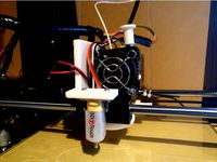
Anet A6 BLTouch/3DTouch mount (front) by thvranken
...isplay or with command m851) and saved to the eeprom (using the display or with command m500), in my case, this was around -2 mm.
thingiverse
free
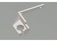
12 mm Sensor mount for Anet A6 by Askot
...-5 // y offset: -front +behind [the nozzle]
#define z_probe_offset_from_extruder 0 // z offset: -below +above [the nozzle]
thingiverse
free

Right Side 18mm Sensor Anet A8 Stock by lordjg
...t_probe_bed_position 42
define right_probe_bed_position 207
define back_probe_bed_position 200
define front_probe_bed_position 15
thingiverse
free
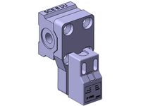
Sensor Mount for Anet A8 by mulger
...0 // y offset: -front +behind [the nozzle]
//#define z_probe_offset_from_extruder 0 // z offset: -below +above [the nozzle]
thingiverse
free

E3D Anet Sensor Extruder by cfresh
...robe_bed_position 20
#define right_probe_bed_position 195
#define front_probe_bed_position 20
#define back_probe_bed_position 170
thingiverse
free

Anet A8 BLTouch Holder by jvyoralek
...e-homing
#define z_safe_homing
define servo
#define num_servos 1
if you spot any issues with item please let me know in comments.
thingiverse
free

18mm auto level sensor support for Anet A8 right side by lukeskymuh
...6 // y offset: -front +behind [the nozzle]
#define z_probe_offset_from_extruder -2.90 // z offset: -below +above [the nozzle]
thingiverse
free
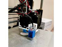
Anet A8 extruder fan and PL08N holder by egusa999
...ions in the firmware marlin2.0:
//nozzle-to-probe offsets { x, y, z }
#define nozzle_to_probe_offset { -30, -40, (your setting) }
thingiverse
free

Anet A8 probe holder right (18mm) by dacoon
... y offset: -front +behind [the nozzle]
#define z_probe_offset_from_extruder 0 // z offset: -below +above [the nozzle]
have fun
thingiverse
free
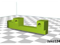
Anet A8 Sensor Bracket by Jako124
...t_probe_bed_position 25
define right_probe_bed_position 194
define back_probe_bed_position 170
define front_probe_bed_position 20
04N
3d_export
$95

street 04n
...: 33442 - vertice: 39397 attention! - need exteriors scenes, game ready terrain, buildings and props? check rest of our products.
thingiverse
free

MPSM Pro SN-04N adapter by area_512005
...car absolutamente nada, se maneja igual que el sensor anterior.
espero que sirva.
saludos
donaciones: https://paypal.me/ivanbonin
thingiverse
free

Anet A8 Z Axis Auto Level Sensor Mount by Samhutch89
...this project is simple adjustable probe mount for the sn-04n or pl-08n capacitive senor used for auto bed levelling...
thingiverse
free

E3D V6 Volcano + Blower + Proximity Sensor Bowden Mount by WayneWeng
...5015 fan. for auto bed leveling, i use fotek pm12-04n inductive proximity sensor. with 4mm metal trigger distance. other...
cg_trader
$95

Street 04N
...street 04n
cg trader
3d street 04n apartment architecture, formats max, obj, 3ds, fbx, c4d, blend, ready for 3d animation and ot
3dwarehouse
free

AFGI-04N
...r #logocad #megacad #one_space_designer #online_3d_part_library #partsolutions #proe_wildfire #solidedge #solidworks #unigraphics
3dwarehouse
free

AFRR-04N
...r #logocad #megacad #one_space_designer #online_3d_part_library #partsolutions #proe_wildfire #solidedge #solidworks #unigraphics
3dwarehouse
free

AFGI-04N
...r #logocad #megacad #one_space_designer #online_3d_part_library #partsolutions #proe_wildfire #solidedge #solidworks #unigraphics
3dwarehouse
free

AFRR-04N
...r #logocad #megacad #one_space_designer #online_3d_part_library #partsolutions #proe_wildfire #solidedge #solidworks #unigraphics
D3Adlydozen
thingiverse
free

Medallion with Olaf by d3adlydozen
...medallion with olaf by d3adlydozen
thingiverse
olaf :)
thingiverse
free

Template of deatch by d3adlydozen
...template of deatch by d3adlydozen
thingiverse
template of deatch.
thingiverse
free

Eye of hand Medalion by d3adlydozen
...eye of hand medalion by d3adlydozen
thingiverse
eye of hand medalion.
thingiverse
free

Big Mazy Clock by d3adlydozen
...big mazy clock by d3adlydozen
thingiverse
big mazy clock v.1
thingiverse
free

Air vent circle 10cm by d3adlydozen
...air vent circle 10cm by d3adlydozen
thingiverse
air vent.
thingiverse
free

Spiral vase, pen holder by d3adlydozen
...spiral vase, pen holder by d3adlydozen
thingiverse
spiral vase or pen holder.
thingiverse
free

Fan Cover 30x30 by d3adlydozen
...fan cover 30x30 by d3adlydozen
thingiverse
fan cover 30 cm x 30 cm for anet a6/a8
thingiverse
free

Case iPhone 5 - Eye of hand by d3adlydozen
...case iphone 5 - eye of hand by d3adlydozen
thingiverse
case iphone 5 - eye of hand
thingiverse
free

Cover power Anet logo by d3adlydozen
...cover power anet logo by d3adlydozen
thingiverse
cover power with anet.
upgrade: cover power logo anet v2.stl
thingiverse
free

Anet A6 - Z_calibrator witch wings by d3adlydozen
...anet a6 - z_calibrator witch wings by d3adlydozen
thingiverse
anet a6:
extruder: 210 c
bed: 50 c
speed: 60 ms
time: 23 min
Autolevel
thingiverse
free

Autolevel by Lo_Copio_too
...autolevel by lo_copio_too
thingiverse
autolevel.
https://youtu.be/9idq1xy8i6i
thingiverse
free

Autolevel Fix by Kevinalign
...autolevel fix by kevinalign
thingiverse
to fix the bar of the optic autolevel, with a 3m screw
thingiverse
free

TronxyX5 Autolevel Holder
...tronxyx5 autolevel holder
thingiverse
tronxy x5 holder for pl-08n autolevel sensor
thingiverse
free

Silenciador de autolevel - Autolevel silencer by BFBA
...need to be corrected with a file after printing in order to work properly. the autolevel installed is a "3d touch" one.
thingiverse
free

Silenciador de autolevel - Autolevel silencer by BFBA
...need to be corrected with a file after printing in order to work properly. the autolevel installed is a "3d touch" one.
thingiverse
free

autolevel probe retractor by mming1106
...autolevel probe retractor by mming1106
thingiverse
autolevel probe retractor
thingiverse
free

easy autolevel by obdiy
...easy autolevel by obdiy
thingiverse
simple carriage for z- autoleveling
for direct-drive extruders (i use mk7/mk8)
thingiverse
free

Autolevel probe by eca3d
...robe by eca3d
thingiverse
autolevel probe for printer rostock.
description here: http://eca3d.blogspot.ru/2014/05/rostock-5.html
thingiverse
free

Autolevel Gehäuse by IW3D
...el gehäuse by iw3d
thingiverse
selbstgebauter autolevel sensor mit gehäuse mit deckel
material pla von bq orange 1.75 nozzel 0,4
thingiverse
free
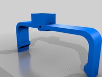
Autolevel FLSUN QQ-S
...el flsun qq-s
thingiverse
autolevel switch
with https://aliexpress.ru/item/32915708033.html?spm=a2g0s.9042311.0.0.274233edtlbqkq
Sn
turbosquid
$10

SN-559 Sniper rifle
... available on turbo squid, the world's leading provider of digital 3d models for visualization, films, television, and games.
3ddd
free

GRAMERCY HOME - Sconce SN 020-1BRS
...gramercy home - sconce sn 020-1brs
3ddd
gramercy home
gramercy home
sconce
sn 020-1brs
www.gramercy-home.ru/
3ddd
free

GRAMERCY HOME - Sconce SN 011-1BRS
...gramercy home - sconce sn 011-1brs
3ddd
gramercy home
gramercy home
sconce
sn 011-1brs
www.gramercy-home.ru/
turbosquid
$28

Signora Sn Phillippo's Armchair
... available on turbo squid, the world's leading provider of digital 3d models for visualization, films, television, and games.
3ddd
$1

Подсветка картин Brille SW-13 2 SN
... sw
http://brille.ua/nastennyye-potolochnyye-svetilniki/podsvetka-kartin/139484.html
3d_ocean
$15

Sneakers SN-1
...than engaged in rendering, so the quality is not the best rendering. about the model i want to say that the mesh is made quali...
3d_export
$10

SNS Popularity VARM Tea Maker
...~ 100,000 model parts: 1 texture format: .png .jpg resolution: 1024*1024 pbr in substance painter formats: .obj .gltf .fbx .blend
3ddd
$1
Hudson Valley Lighting 7509-SN Woodstock 1 Light Flush Mounts
...tock 1 light flush mounts
артикул: 7509-sn
материал: satin nickel
остальное здесь:http://www.hudsonvalleylighting.com/
3ddd
$1

Savoy House / 1-1726-6-SN
...кой фабрики savoy house, артикул 1-1726-6-sn.http://www.savoyhouse.com/sutton-place-6-light-chandelier-1-1726-6-sn.html
3ddd
$1

Светильники Savoy House Europe Pauline
...60w, бра se-9-1027-2-sn / 2x e14 - 100w, бра se-9-1027-1-sn / 1x e14 -...
A6
3ddd
free

audi a6
...audi a6
3ddd
audi a6
audi a6
3ddd
$1

AUDI A6
...audi a6
3ddd
audi
audi a6, — семейство легковых автомобилей бизнес-класса, выпускающихся под маркой audi
3ddd
$1

Slipper Bath A6
...slipper bath a6
3ddd
toto
slipper bath a6
3ddd
$1

Slipper Bath A6
...slipper bath a6
3ddd
toto , ванна
slipper bath a6
3d_export
$40

Audi A6 3D Model
...audi a6 3d model
3dexport
audi a6
audi a6 3d model kaxa3d 8037 3dexport
3d_export
$79

Audi A6 3D Model
...audi a6 3d model
3dexport
audi auto a6
audi a6 3d model growl 3313 3dexport
3d_export
$40

Audi a6 3D Model
...audi a6 3d model
3dexport
car audi a6
audi a6 3d model bararhakopre20 91055 3dexport
turbosquid
$99

Audi A6
... available on turbo squid, the world's leading provider of digital 3d models for visualization, films, television, and games.
turbosquid
$99

Audi A6
... available on turbo squid, the world's leading provider of digital 3d models for visualization, films, television, and games.
turbosquid
$90

Audi A6
... available on turbo squid, the world's leading provider of digital 3d models for visualization, films, television, and games.
Anet
thingiverse
free

Anet by derbodesign
...anet by derbodesign
thingiverse
logo anet
thingiverse
free
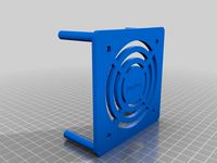
Anet e10 , Anet v1.0 by jonathan_943D
...anet e10 , anet v1.0 by jonathan_943d
thingiverse
soporte de ventilador de 80mm, para controladora anet v1.0
thingiverse
free
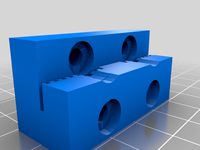
Anet A8 Anet AM8 Y belt holder
...anet a8 anet am8 y belt holder
thingiverse
anet a8 anet am8 y belt holder
thingiverse
free
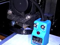
Anet A8 Probe Bracket for anet sensor by chelrix
...anet a8 probe bracket for anet sensor by chelrix
thingiverse
anet a8 probe bracket for anet official sensor and marlin firmware
thingiverse
free
Anet logo by JUST3D_PRNTNG
...anet logo by just3d_prntng
thingiverse
anet logo
thingiverse
free
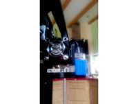
Fan nozzle for Anet A8 with original Anet levelsensor by peteruhlmann
...et levelsensor by peteruhlmann
thingiverse
here is an improved fan nozzle for the anet a8 with original level sensor from anet.
thingiverse
free
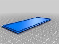
Anet Et4 Box
...anet et4 box
thingiverse
tool box for anet et4
thingiverse
free
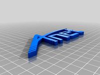
Anet Logo by Superflex_Plastic_Fantastic
...anet logo by superflex_plastic_fantastic
thingiverse
anet logo to incorporate into designs.
thingiverse
free
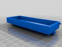
Box for Anet ET4
...box for anet et4
thingiverse
this is a simple box for tool of anet et4
thingiverse
free

Anet V1.0 Board Kühlung (80mm Lüfter) / Anet A8 by MadCre8
...anet v1.0 board kühlung (80mm lüfter) / anet a8 by madcre8
thingiverse
anet v1.0 board kühlung (80mm lüfter) / anet a8
Sensor
3d_export
free

parking sensor
...parking sensor
3dexport
car parking sensor
turbosquid
$1
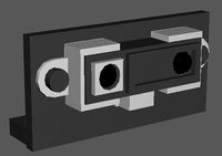
Sensor
... available on turbo squid, the world's leading provider of digital 3d models for visualization, films, television, and games.
3d_export
$5
Smoke sensor
...port
smoke sensor, can be an impressive element for your projects. easy to use, realistic image, low polygon, quality materials.
3d_export
$5
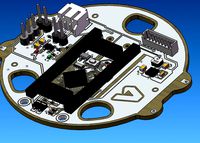
Air Quality Sensor v1
...air quality sensor v1
3dexport
air quality sensor v1
3d_export
$15
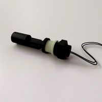
float sensor
...e up render. - all parts and materials are logically named. other formats ================= - collada (.dae) - autodesk fbx - obj
turbosquid
$26
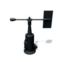
Wind sensor C
...free 3d model wind sensor c for download as 3ds, obj, and fbx on turbosquid: 3d models for games, architecture, videos. (1328943)
turbosquid
$26
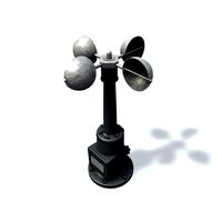
Wind sensor B
...free 3d model wind sensor b for download as 3ds, obj, and fbx on turbosquid: 3d models for games, architecture, videos. (1328168)
3d_export
$5
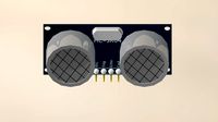
ultrasound sensor
...ivers convert ultrasound into electrical signals, and transceivers can both transmit and receive ultrasound. export in: -obj -fbx
3ddd
free
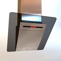
Вытяжка Shindo pallada sensor
... вытяжка
вытяжка shindo pallada sensor. в двух размерах - 600 и 900. текстуры в комплекте.
turbosquid
$52
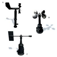
Wind sensor A B C
...
royalty free 3d model wind sensor a b c for download as fbx on turbosquid: 3d models for games, architecture, videos. (1408406)
Blue
3d_ocean
$7

blue shrub
...blue shrub
3docean
blue bush flowers shrub
bush with blue flowers
3d_ocean
$7

blue shrub
...blue shrub
3docean
blue bush flowers shrub
bush with blue flowers
3d_export
$12

blue whale
...blue whale
3dexport
blue whale
3d_export
$5

blue chair
...blue chair
3dexport
blue chair
3ddd
$1

Blue curtain
...blue curtain
3ddd
blue curtain
3d_export
$5

blue donut
...blue donut
3dexport
delicious blue donut
3ddd
$1

Blue Dino
...blue dino
3ddd
динозавр
blue dino
3ddd
$1

blue chair
...blue chair
3ddd
blue leather chair
3ddd
$1

Bonaldo / Blues
...bonaldo / blues
3ddd
bonaldo
blues plastic chair by bonaldo
3ddd
$1

blue nature
...blue nature
3ddd
blue nature
зеркало этническое деревянное
Bed
3ddd
$1
bed
...bed
3ddd
bed , постельное белье
bed
3ddd
$1
bed
...bed
3ddd
bed , постельное белье
bed
3ddd
$1
bed
...bed
3ddd
bed , постельное белье
bed
3ddd
$1
bed
...bed
3ddd
bed , постельное белье
bed
3ddd
$1
bed
...bed
3ddd
bed , постельное белье
bed
3ddd
$1

bed
...bed
3ddd
bed , постельное белье
bed
3ddd
free
bed
...bed
3ddd
bed , постельное белье
bed
3ddd
free
bed
...bed
3ddd
bed , постельное белье
bed
3ddd
$1
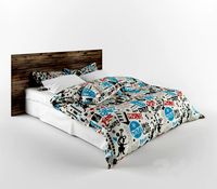
Bed
...bed
3ddd
bed , постельное белье , постель
bed
3d_export
$7
bed adairs bed
...rs bed
3dexport
bed adairs bed in modern style. if you want a smoother surface, please turn on turbosmooth in the modifier list.