Thingiverse
Amstrad PCW mini
by Thingiverse
Last crawled date: 4 years, 2 months ago
Amstrad PCW mini:
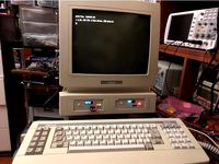
The Amstrad PCW is a much underrated series of computers that were primarily marketed as affordable all-in-one word processors that could also run CP/M.
These days they make excellent retro machines, especially as there's a huge catalogue of CP/M software to play with...
...better still the word processing software they came with was very good and still very usable if you like the command line approach...
...there's a wide range of PCW specific software and lots of games as the machine was often bought by the people who might otherwise buy a home computer such as an Amstrad CPC. Oh, and SymbOS runs on the PCW should you want to run a modern, multitasking, graphical OS on a 4Mhz Z80.
What is this PCW mini?
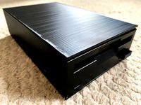
PCW's are still readily available from the likes of fleaBay at good prices. Working motherboards and keyboards also come up regularly for next-to-nothing and that's where this project comes in - A fully functioning PCW only the size of a PCW keyboard, with USB based storage, that hooks up to a composite display while remaining compatible with most add-ons.
This is going to be a quite extensive 'thing' that initially aims at being a guide to building a fully functional PCW computer built in to a PCW 8256/8512 keyboard. later updates will include plans for doing some serious upgrades so do keep coming back from time to time.
31.10.19: Part One
Required Parts:
All of these can usually be found on eBay but please don't destroy a functioning PCW machine for parts.
-A functioning PCW 8256/8512 keyboard
-A functioning PCW motherboard
-A PicoPSU power supply - my choice, many other options possible
-A 12v power brick with a center positive connector that fits the motherboard power socket
I would strongly recommend an 8256 or 8512 motherboard as this will raise the fewest compatibility issues, and this guide will be based around this motherboard. Any PCW motherboard will do as long as it's NOT from a PCW 16 but you'll need to adjust measurements for the board you choose.
-Some Nylon nuts and bolts to fit through the motherboard mounting holes
-A Gotek floppy drive emulator
-A USB to FTDI adapter
-A USB stick, just a cheap low capacity one is fine
-A PC of some description
-A copy of Adobe 123D Design would be helpful but not required
-Some perf board
-Small hand files
-A steel ruler, preferably one with a right-angle
-Some painter's tape
-Some basic hobbyist electronic supplies and soldering equipment - further details when we get that far...
...and the files provided here.
-Glue - I would suggest hot glue, at least for starters, as it's good enough and easy-ish to remove if needed. Epoxy is a much stronger option but best reserved for final assembly once you know everything is good.
Let us begin:
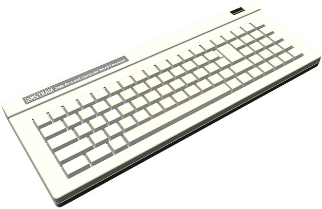
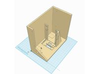
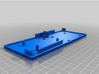
i) Load up your one of the PCWmini 3D files and take a good look. You will find an accurate (not perfect) mock up of an Amstrad PCW 8256 keyboard. If you compare it to a physical example you will see it has a few extra cut-outs.
From the rear, right to left:
-Power socket
-Printer port
-Expansion connector
-Composite video connector
From the right:
-A cutout for access to the Gotek floppy emulator
From the top:
-A cutout for an OLED display to connect to the Gotek
The measurements are pretty darn accurate but before cutting I would suggest fully dissembling the keyboard and offering up your PCW motherboard to the lower shell, especially if you aren't using a 8256/8512 motherboard.
-See the file(s) 8XXXX_Assembly - 8XXXX_Assembly.123dx includes some useful annotations.
You will notice the motherboard won't fit for three reasons:
a) The various mounting posts in the shell base are in the way
b) You haven't opened up the port cut-outs yet
c) The motherboard is too big... what!?!
a) Use your Dremmel to remove the mounting hardware so you end up with a reasonably flat base.
b) Check the motherboard against the lower shell to be sure you are happy with the supplied measurements within the 3D models.
At this point I would suggest applying painter's tape to the areas to be cut and carefully marking the cutouts on the tape. Carefully cut the plastic JUST INSIDE your markings with the Dremmel and finish with the files - take your time, measure twice and cut once. It's much easier to remove plastic than replace it!
c) WTF!?!
Yes the motherboard won't fit and will need cutting. Don't fear it's not as drastic or difficult as you might think. Take a good look at the motherboard in conjunction with one of the 8xxx_Motherboard file, There are two cuts to be made:
1) You need to cut about 5-8mm from the front edge in line with the bottom of the "Amstrad PCW 8xxx" text embossed in to the 3D file version. The landmarks on the real thing are the wide strip of copper (ground plane) running along the bottom edge. The plan is to make your cut such that 1-2mm of said strip remains post cut. DON'T cut it all off!
Remember that steel ruler with a right-angle on it?
The easiest way to get a neat accurate cut is to turn the motherboard on it's face and lay the ruler on the flatter underside using the right-angle of the ruler and edge of the board to ensure a parallel cut. Re, re, re-check, and check again that all is positioned to your satisfaction then run a Dremmel cutting wheel along the motherboard using the steel ruler as a guide.
All being well you will have a perfect cut that hasn't removed all of that copper strip.
Oh, and fibreglass dust isn't that good for you so try not to breathe it in.
Offer the motherboard up to your recently modified lower keyboard shell and curse loudly when you find the dang thing still wont fit.
2) Look carefully to see how much overlap there still is and get ready to perform the same task on the opposite edge of the PCB from the one you just made. The part you want to cut is under the power socket and printer port
-Don't cut the expansion port edge connector
-Take care not to cut in to the plastic housings of the ports as you remove a sliver of PCB
-You shouldn't need to go bananas
3) Once done offer up the motherboard yet again and you should find it fits snugly in to the plastic shell.
Note: The plan is that it should fit in to the (previously flattened) base but not cover the slight lip along the inside of the front lip
Done? Good, that's the scary stuff over with... possibly.
The last task for today is to get your PCW motherboard ready for it's new home. Break out your soldering equipment and here we go.
You need to remove:
-The large power supply connection posts to the left of the PCB
-The wires for the floppy power connectors to the left and right of the floppy ribbon cable connector
-The keyboard connection header, top-right of the motherboard. NOT the video header just below it!
These are clearly marked in the 8XXX_Assembly.123dx 3D file.
I'll add photos in due course...
I think that will do for now. Next time we'll tackle:
-Modifying the floppy ribbon cable for connection to the Gotek
-Modifying the Gotek for use with the PCW
-Mounting both neatly within the lower shell
-Mounting and connecting up the PSU and a power switch
2.11.19 Part Two
Floppy Ribbon Cable Modification:
There are some important considerations when connecting a floppy drive such as a Gotek floppy emulator to a PCW.
Machines that came with 3" floppies won't connect directly to 3.5" drives and most of the ones that did have 3.5" drives use the very uncommon 26pin powered cable standard that will kill a standard 3" or 3.5" drive if connected without an adapter. This guide concentrates on using a 8256/8512 motherboard that had a 3" drive connected as standard but I will go over what to do if you chose a motherboard that came equipped with a 3.5" drive.
3" Drive connection:
The 8256/8512 used exactly the same drive as Amstrad's CPC range so if you find the following confusing do a bit of googling and find a guide that does make sense.
1) Parts
i) A floppy cable connector for a standard 3.5" drive, new or recycled
ii) A sharp knife and small flat-head screwdriver
iii) Maybe some glue and plasters for cut fingers
iv) Care and lots of patience!
2) Examine the floppy ribbon cable attached to the motherboard - don't remove it! But do cut the far end floppy drive connector from the cable as neatly as possible, as close to the connector as you can. You don't need this any more.
3) Look for the red stripe along one edge of the cable indicating pin one. Counting from that side you want to split the end of the cable so there are six (6) cores on one side and so twenty (20) cores on the other side. The split doesn't need to be long but be careful to count correctly and don't damage the cable so showing the wires - fingernails are usually good enough, don't use something sharp!
4) Take your new (much easier) or recycled (an utterly fiddly b^stard to disassemble without destroying) 3.5" floppy connector and place the PCW's cable within it's 'jaws' such that:
-The 20 core (without the red stripe) side is pushed up against the side as far as it will go
-The 6 core (with the red stripe) fits in the the ''jaws' such that there is a gap of exactly two (2) cores between each partit's easy enough to tell on close inspection as the top half of the 'jaws' has obvious indentations to help guide the cable in to place. Try not to have too much wasted cable sticking out of the far side - there is spare, but not a lot, and you might need the spare if you need another go.
5) While keeping everything properly lined up and in place (fiddly!) squeeze the jaws shut until the cable is properly clamped down and the retaining tabs have clicked in to place. Check against the old connector for comparison. If you need another go make sure to cut the damaged cable away first, you want to clamp to fresh cablechances are your fingers won't be anywhere near strong enough to do this so assuming you don't have the correct tool I have found two methods that work well:
i) Place the somewhat assembled connector under a table leg and having checked all is properly lined up sit on the table!
ii) The hinge of a suitable door can be your friend when you want to apply even pressure to a connector that you don't otherwise have to leverage to squeeze shut
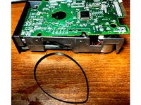
6) You should now have a floppy connector where the wider part of the cable butts-up against the side of the housing, there is a gap of two cores, then the narrower part with a red stripe on the outside. There should be no twists in the cable and you will notice there's a further gap to the other side of the housing. Job done, see the photo for one I did earlieras I made mine from a recycled hard drive connector I had too much spare connector overhanging so cut the end off and glued it - do take this in to account!
7) It's sensible to trim the excess cable but do make sure it's neat and the free ends of the wires aren't shorted - best achieved with a very sharp knife or scissors.
...what about PCW's fitted with 3.5" drives?
You have two options:
1) As the unusual Amstrad drives use a powered cable just use that and don't bother with the Gotek...
...of course that's going to be a bit janky as the drive will have to dangle on the end of a cable and you'll be stuck using hard to find and increasingly unreliable floppies.
2) See the included files. One is called 34Pin_Floppy.zip. This contains images for constructing a DIY adaptor for the job. Fiddly to solder but if you follow the design exactly (123dx file included) you will have something that will mate the floppy cable connector directly to a Gotek. Make it from perf-board or Eagle PCB files are included should you feel like having a proper PCB made.
Gotek Modification:
This section is going to be a 'high level' overview plus some files. The reason being there are already very detailed resources for doing this properly.
Flash Floppy Firmware: https://github.com/keirf/FlashFloppy
Firmware Flashing Instructions: https://github.com/keirf/FlashFloppy/wiki/Firmware-Programming
Hardware Mods: https://github.com/keirf/FlashFloppy/wiki/Hardware-Mods
Parts:
-A Gotek floppy drive and a USB to FTDI adapter
-Some female patch wires are a good idea
-A computer from which to run the flashing software
Firmware flashing?
The standard Gotek is quite capable of emulating PC-type floppy drives but struggles with non-standard floppy formats. That's not a biggie, the Gotek can be reprogrammed to handle a much wider variety of options hence the new firmware written by the awesome keirf. It's not hard as long as you follow the instructions to the letter. The only things I would say are:
i) Make sure the drivers for your FTDI adapter are set to the same speed as the flashing software
ii) Assuming, like me, you power the Gotek from the FTDI adapter be sure said adapter is set to 5v, not 3.3v, and that BOTH the ground for the adapter AND the ground in the FTDI connector are connected to the ground of the Gotek to improve reliability - this one had me scratching my head for a while.
Hardware mods:
Once flashed the Gotek will run fine as-is but be sure you have removed all the jumpers after flashing and then add a jumper across the S0 pins prior to use or it won't work.
You will have noticed from the Hardware Mods page there are lots of additions you can make to your Gotek. As a sensible minimum I would strongly suggest the following:
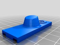
i) Get a 7mm tact switch and connect it up. Having a separate insert / eject button is really helpful. The switch itself will fit between the standard ones and the USB port - just hot-glue it in, being careful not to gum the switch up in the process
ii) Replacing the segmented display with a 128x32 OLED display makes a huge difference to ease of use, is dead-easy, and they cost buttons. Given the position I elected to place the OLED cutout in the upper shell of the keyboard you might find extending the connections wires helpful.
Mounting the PCB's
Assuming you have already modified the plastics, the PCW motherboard, and the Gotek it's time to sort a mounting solution.
Parts:
-Some short M5 Nylon nuts and bolts
-Some glue (I'd suggest hot glue sticks for now)
-A heat source
1) Take a look at your motherboard. Assuming you have an 8256/8512 version that's been cut down as suggested you will see a number of likely holes to use a mounting points.
-One bottom-left next to the plastic buzzer housing
-Two top-left either side of the printer port (these may need freeing of solder)
-One Top-right next to the expansion port
You don't want to use the two holes between the printer port and expansion connector
2) Push one of your M5 Nylon bolts through each of these holes from the underside and loosely secure with a nut. Then place the motherboard in the shell to check fitment. All should be good and you're aiming to have the PCB as far left as it will go. Happy?
3) Remove the board, melt the end of a hot-glue stick (in a flame) and apply a blob to the head head of one of the bolts. Quickly, but carefully, return the motherboard to it's final location and press down on the hot-glued bolt.
4) Wait a mo' then carefully unscrew the nut for that bolt and remove the PCB. You should now have a perfect stand-off in place. If you weren't quick enough, used too much glue, or were too brutal removing the motherboard, you might need to try again.
5) Repeat this process for the other mentioned holes, Nearly done. For the final fit the plan is to run the floppy cable under the motherboard so it comes up at the back between the printer and expansion ports. Depending on tolerances you might need to grind a little plastic from the inside of the lower keyboard shell to allow room for the cable. This way it's neat and you have the potential option to fit a second floppy drive via a further cut-out.
6) I would advise adding on final stand-off for the bottom-right corner of the motherboard. Drill a hole if you wish but just seating the nut a bolt such that they will hold the edge of the PCB will be fine.
7) The process for the Gotek PCB is exactly the same but you want that pushed top-right as far as you can go...
...at this point you probably noticed the cutout from the plans isn't quite wide enough. Sorry, quite deliberate. The cut-outs in the 3D files are very easy to close should anyone desire an accurate case mock-up, but not it I had extended the Gotek cut-out all the way.
Optional
Hot-glue isn't amazingly strong but is easy enough to work with and will do the job. If you feel greater strength is required feel free to add some epoxy round each bolt head. Just don't go above the bolt heads, you want the PCB as low in the case as possible while keeping the undersides out of contact with the shell.
Power Supply:
It's really up to you how you do this bit. If you don't plan on connecting anything else to your PCWmini you only need to provide +5v and GND. A 5v power brick that supplies 2 amps (for safety) will be more than enough. I've gone with a PicoPSU for three reasons:
-I had one kicking around
-It will supply 12v which will be useful for some upgrades
-I want to reuse that power connector
PicoPSU's come in two 'flavors'. Those intended to take a 12v supply and those tolerant of of higher voltages. If you intend to hook up the PCW printer it would be sensible to go for the latter and a 24v power brick so everything can be run off one supply.
Parts:
-A PicoPSU
-Some decently thick wire, possibly recycled from an old PC PSU
-Some shrink-wrap
-A latching button switch small enough to fit in the the keyboard cable hole
-The image showing the ATX header pin-out
-The PCW Connections.txt file for the motherboard wiring
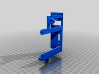
I would advise placing your PicoPSU as illustrated in my 3D files: Just to the right of the motherboard and just below the Gotek.
1) Take your Pico PSU and desolder the flying leads that connect it's power input jack.
2) Remember the motherboard power input headers you desoldered? Counting back to front the pins are:
Power
1 - GND (24v)
2 - GND (5v, 12v)
3 - +5v
4 - +12v
5 - +24v
Run two suitable wires (red and black) from the desoldered PicoPSU input to Pin 1 of the motherboard header (GND) and Pin 5 of the same header (+24v). The PicoPSU can now get it's power from the existing power jack on the motherboardoriginally intended as a 24v power out for the printer, now re-purposed as a 12/24v power in for the PSU.
2) Remove the plug-in harness from the PicoPSU and cut the Molex connectors from it leaving as much wire as possible.
Traditionally:
Yellow = 12v
Black x2 = GND
Red = 5v
You have two options:
i) You can solder those wires to the floppy drive power header to the right of the floppy ribbon cable connector you previously removed - do be careful to connect correctly (L>Yellow, Black, Black, Red>R). This will supply +12v. GND, and +5v for the motherboard by 'injecting' the supply down this 'output'.
or
ii) You can extend these wires and run them up to the main 12v, 5v, and GND input pins. If you do so be sure to connect the two GND wires together and connect to the GND (5v, 12v) pin ONLY. The GND (24v) pin should only be used for the PIcoPSU's supply.
3) Next you need to run power to your Gotek. I would suggest recycling one of the floppy power cables you removed earlier. The power input pins for the Gotek run left-right 12v, GND, GND, 5v. Only 5v and one of the GND pins need connecting. I would advise taking these power lines direct from the PicoPSU - Solder the wires to appropriate pins on the back of the ATX header - see the pinout image.
4) Finally we want a Power Switch. Take your latching button switch and test which pins are connected / disconnected when you press the button. You want to solder wire to each of these. As it happens I first soldered the switch to a sliver of perf-board so the following hot-gluing would be more secure.
On inspection of the ATX connector pin-out you will see a 'green' pin labeled 'PS_ON#' with a pin labeled 'COM' right next to it. You want to solder the two wires from your switch to these, either way round. The PSU now has an ON/OFF.
Note: It is often said when repurposing an ATX PSU you should add a resistor across GND and +12v to give it a load - ATX PSU's don't like being turned on if they are unloaded. Even if there is no damage they can produce very unstable output. That should not be an issue here as the PSU has a load permanently connected to it. ie: The Computer!
5) Go hot-glue the power switch to the lower shell in the cut-out where the keyboard cable used to be. Use plenty of glue, that switch is going to get some abuse, but be sure everything still fits together.
6) Finally the PicoPSU can be attached to the case with the same hot-glue 'n Nylon bolts method used earlier. I'd suggest connector side up which means cutting off the clip in the ATX connector.
I think that will do for today. I will post some photo's, honest! We'll tackle the keyboard next as well as setting up the Gotek and supplying some files to run on the machine.
IMPORTANT
As we get closer there will be the temptation to fire up the machine and give it a test. Understandable, but DON'T!
It will work in it's current state, and will even give an angry BEEP when it can't find a floppy to boot from. But you'll be tempted to hook the composite header up to a monitor, which may well damage the machine. If you, temporarily, get away with it you might then be tempted to hook up the keyboard which will result in an escape of magic smoke if you're not aware of the hidden 'gotcha'.
5.11.19 Part Three
It's bonfire night which is quiet appropriate if you get this wrong so pay attention.
The Keyboard Mechanism:
Up to now it's been a 'case' of turning a keyboard in to a computer we now need to make it function as a keyboard again.
1) Modifications:
i) If you already tried to place the keyboard back in the case, depending on how neat you were with your wiring, you might find it won't seat properly because the keyboard's PCB is too close to the Gotek below it.
The plan here is pretty simple. Unscrew the PCB from the keyboard itself and cut the standoffs down such that the PCB components don't quite touch the back of the body of the keyboard - about 5mm.
ii) Depending on tolerances the plastic motherboard floppy ribbon cable connector may be too tall - mine was because of how bad it was soldered. I wouldn't suggest re-soldering it, take out your trusty Dremmel and grind just enough of the top off to allow the keyboard to seat properly, concentrating on the front edge.
iii) Now for connection to the motherboard. Pay Careful Attention!
-If you haven't done so already unplug the cable from the keyboard PCB and cut the din plug from the four wires that go to it as close as you can. That's the external plug NOT the molex connector that was plugged in to the PCB
-Optionally desolder the keyboard PCB four pin header that you just removed the cable from and resolder to the underside of the PCB - This will make fitting the Gotek OLED much easier.
Now comes the important bit; get this wrong and you'll have an escape of black smoke!
The Amstrad PCW is a much underrated series of computers that were primarily marketed as affordable all-in-one word processors that could also run CP/M.
These days they make excellent retro machines, especially as there's a huge catalogue of CP/M software to play with...
...better still the word processing software they came with was very good and still very usable if you like the command line approach...
...there's a wide range of PCW specific software and lots of games as the machine was often bought by the people who might otherwise buy a home computer such as an Amstrad CPC. Oh, and SymbOS runs on the PCW should you want to run a modern, multitasking, graphical OS on a 4Mhz Z80.
What is this PCW mini?
PCW's are still readily available from the likes of fleaBay at good prices. Working motherboards and keyboards also come up regularly for next-to-nothing and that's where this project comes in - A fully functioning PCW only the size of a PCW keyboard, with USB based storage, that hooks up to a composite display while remaining compatible with most add-ons.
This is going to be a quite extensive 'thing' that initially aims at being a guide to building a fully functional PCW computer built in to a PCW 8256/8512 keyboard. later updates will include plans for doing some serious upgrades so do keep coming back from time to time.
31.10.19: Part One
Required Parts:
All of these can usually be found on eBay but please don't destroy a functioning PCW machine for parts.
-A functioning PCW 8256/8512 keyboard
-A functioning PCW motherboard
-A PicoPSU power supply - my choice, many other options possible
-A 12v power brick with a center positive connector that fits the motherboard power socket
I would strongly recommend an 8256 or 8512 motherboard as this will raise the fewest compatibility issues, and this guide will be based around this motherboard. Any PCW motherboard will do as long as it's NOT from a PCW 16 but you'll need to adjust measurements for the board you choose.
-Some Nylon nuts and bolts to fit through the motherboard mounting holes
-A Gotek floppy drive emulator
-A USB to FTDI adapter
-A USB stick, just a cheap low capacity one is fine
-A PC of some description
-A copy of Adobe 123D Design would be helpful but not required
-Some perf board
-Small hand files
-A steel ruler, preferably one with a right-angle
-Some painter's tape
-Some basic hobbyist electronic supplies and soldering equipment - further details when we get that far...
...and the files provided here.
-Glue - I would suggest hot glue, at least for starters, as it's good enough and easy-ish to remove if needed. Epoxy is a much stronger option but best reserved for final assembly once you know everything is good.
Let us begin:
i) Load up your one of the PCWmini 3D files and take a good look. You will find an accurate (not perfect) mock up of an Amstrad PCW 8256 keyboard. If you compare it to a physical example you will see it has a few extra cut-outs.
From the rear, right to left:
-Power socket
-Printer port
-Expansion connector
-Composite video connector
From the right:
-A cutout for access to the Gotek floppy emulator
From the top:
-A cutout for an OLED display to connect to the Gotek
The measurements are pretty darn accurate but before cutting I would suggest fully dissembling the keyboard and offering up your PCW motherboard to the lower shell, especially if you aren't using a 8256/8512 motherboard.
-See the file(s) 8XXXX_Assembly - 8XXXX_Assembly.123dx includes some useful annotations.
You will notice the motherboard won't fit for three reasons:
a) The various mounting posts in the shell base are in the way
b) You haven't opened up the port cut-outs yet
c) The motherboard is too big... what!?!
a) Use your Dremmel to remove the mounting hardware so you end up with a reasonably flat base.
b) Check the motherboard against the lower shell to be sure you are happy with the supplied measurements within the 3D models.
At this point I would suggest applying painter's tape to the areas to be cut and carefully marking the cutouts on the tape. Carefully cut the plastic JUST INSIDE your markings with the Dremmel and finish with the files - take your time, measure twice and cut once. It's much easier to remove plastic than replace it!
c) WTF!?!
Yes the motherboard won't fit and will need cutting. Don't fear it's not as drastic or difficult as you might think. Take a good look at the motherboard in conjunction with one of the 8xxx_Motherboard file, There are two cuts to be made:
1) You need to cut about 5-8mm from the front edge in line with the bottom of the "Amstrad PCW 8xxx" text embossed in to the 3D file version. The landmarks on the real thing are the wide strip of copper (ground plane) running along the bottom edge. The plan is to make your cut such that 1-2mm of said strip remains post cut. DON'T cut it all off!
Remember that steel ruler with a right-angle on it?
The easiest way to get a neat accurate cut is to turn the motherboard on it's face and lay the ruler on the flatter underside using the right-angle of the ruler and edge of the board to ensure a parallel cut. Re, re, re-check, and check again that all is positioned to your satisfaction then run a Dremmel cutting wheel along the motherboard using the steel ruler as a guide.
All being well you will have a perfect cut that hasn't removed all of that copper strip.
Oh, and fibreglass dust isn't that good for you so try not to breathe it in.
Offer the motherboard up to your recently modified lower keyboard shell and curse loudly when you find the dang thing still wont fit.
2) Look carefully to see how much overlap there still is and get ready to perform the same task on the opposite edge of the PCB from the one you just made. The part you want to cut is under the power socket and printer port
-Don't cut the expansion port edge connector
-Take care not to cut in to the plastic housings of the ports as you remove a sliver of PCB
-You shouldn't need to go bananas
3) Once done offer up the motherboard yet again and you should find it fits snugly in to the plastic shell.
Note: The plan is that it should fit in to the (previously flattened) base but not cover the slight lip along the inside of the front lip
Done? Good, that's the scary stuff over with... possibly.
The last task for today is to get your PCW motherboard ready for it's new home. Break out your soldering equipment and here we go.
You need to remove:
-The large power supply connection posts to the left of the PCB
-The wires for the floppy power connectors to the left and right of the floppy ribbon cable connector
-The keyboard connection header, top-right of the motherboard. NOT the video header just below it!
These are clearly marked in the 8XXX_Assembly.123dx 3D file.
I'll add photos in due course...
I think that will do for now. Next time we'll tackle:
-Modifying the floppy ribbon cable for connection to the Gotek
-Modifying the Gotek for use with the PCW
-Mounting both neatly within the lower shell
-Mounting and connecting up the PSU and a power switch
2.11.19 Part Two
Floppy Ribbon Cable Modification:
There are some important considerations when connecting a floppy drive such as a Gotek floppy emulator to a PCW.
Machines that came with 3" floppies won't connect directly to 3.5" drives and most of the ones that did have 3.5" drives use the very uncommon 26pin powered cable standard that will kill a standard 3" or 3.5" drive if connected without an adapter. This guide concentrates on using a 8256/8512 motherboard that had a 3" drive connected as standard but I will go over what to do if you chose a motherboard that came equipped with a 3.5" drive.
3" Drive connection:
The 8256/8512 used exactly the same drive as Amstrad's CPC range so if you find the following confusing do a bit of googling and find a guide that does make sense.
1) Parts
i) A floppy cable connector for a standard 3.5" drive, new or recycled
ii) A sharp knife and small flat-head screwdriver
iii) Maybe some glue and plasters for cut fingers
iv) Care and lots of patience!
2) Examine the floppy ribbon cable attached to the motherboard - don't remove it! But do cut the far end floppy drive connector from the cable as neatly as possible, as close to the connector as you can. You don't need this any more.
3) Look for the red stripe along one edge of the cable indicating pin one. Counting from that side you want to split the end of the cable so there are six (6) cores on one side and so twenty (20) cores on the other side. The split doesn't need to be long but be careful to count correctly and don't damage the cable so showing the wires - fingernails are usually good enough, don't use something sharp!
4) Take your new (much easier) or recycled (an utterly fiddly b^stard to disassemble without destroying) 3.5" floppy connector and place the PCW's cable within it's 'jaws' such that:
-The 20 core (without the red stripe) side is pushed up against the side as far as it will go
-The 6 core (with the red stripe) fits in the the ''jaws' such that there is a gap of exactly two (2) cores between each partit's easy enough to tell on close inspection as the top half of the 'jaws' has obvious indentations to help guide the cable in to place. Try not to have too much wasted cable sticking out of the far side - there is spare, but not a lot, and you might need the spare if you need another go.
5) While keeping everything properly lined up and in place (fiddly!) squeeze the jaws shut until the cable is properly clamped down and the retaining tabs have clicked in to place. Check against the old connector for comparison. If you need another go make sure to cut the damaged cable away first, you want to clamp to fresh cablechances are your fingers won't be anywhere near strong enough to do this so assuming you don't have the correct tool I have found two methods that work well:
i) Place the somewhat assembled connector under a table leg and having checked all is properly lined up sit on the table!
ii) The hinge of a suitable door can be your friend when you want to apply even pressure to a connector that you don't otherwise have to leverage to squeeze shut
6) You should now have a floppy connector where the wider part of the cable butts-up against the side of the housing, there is a gap of two cores, then the narrower part with a red stripe on the outside. There should be no twists in the cable and you will notice there's a further gap to the other side of the housing. Job done, see the photo for one I did earlieras I made mine from a recycled hard drive connector I had too much spare connector overhanging so cut the end off and glued it - do take this in to account!
7) It's sensible to trim the excess cable but do make sure it's neat and the free ends of the wires aren't shorted - best achieved with a very sharp knife or scissors.
...what about PCW's fitted with 3.5" drives?
You have two options:
1) As the unusual Amstrad drives use a powered cable just use that and don't bother with the Gotek...
...of course that's going to be a bit janky as the drive will have to dangle on the end of a cable and you'll be stuck using hard to find and increasingly unreliable floppies.
2) See the included files. One is called 34Pin_Floppy.zip. This contains images for constructing a DIY adaptor for the job. Fiddly to solder but if you follow the design exactly (123dx file included) you will have something that will mate the floppy cable connector directly to a Gotek. Make it from perf-board or Eagle PCB files are included should you feel like having a proper PCB made.
Gotek Modification:
This section is going to be a 'high level' overview plus some files. The reason being there are already very detailed resources for doing this properly.
Flash Floppy Firmware: https://github.com/keirf/FlashFloppy
Firmware Flashing Instructions: https://github.com/keirf/FlashFloppy/wiki/Firmware-Programming
Hardware Mods: https://github.com/keirf/FlashFloppy/wiki/Hardware-Mods
Parts:
-A Gotek floppy drive and a USB to FTDI adapter
-Some female patch wires are a good idea
-A computer from which to run the flashing software
Firmware flashing?
The standard Gotek is quite capable of emulating PC-type floppy drives but struggles with non-standard floppy formats. That's not a biggie, the Gotek can be reprogrammed to handle a much wider variety of options hence the new firmware written by the awesome keirf. It's not hard as long as you follow the instructions to the letter. The only things I would say are:
i) Make sure the drivers for your FTDI adapter are set to the same speed as the flashing software
ii) Assuming, like me, you power the Gotek from the FTDI adapter be sure said adapter is set to 5v, not 3.3v, and that BOTH the ground for the adapter AND the ground in the FTDI connector are connected to the ground of the Gotek to improve reliability - this one had me scratching my head for a while.
Hardware mods:
Once flashed the Gotek will run fine as-is but be sure you have removed all the jumpers after flashing and then add a jumper across the S0 pins prior to use or it won't work.
You will have noticed from the Hardware Mods page there are lots of additions you can make to your Gotek. As a sensible minimum I would strongly suggest the following:
i) Get a 7mm tact switch and connect it up. Having a separate insert / eject button is really helpful. The switch itself will fit between the standard ones and the USB port - just hot-glue it in, being careful not to gum the switch up in the process
ii) Replacing the segmented display with a 128x32 OLED display makes a huge difference to ease of use, is dead-easy, and they cost buttons. Given the position I elected to place the OLED cutout in the upper shell of the keyboard you might find extending the connections wires helpful.
Mounting the PCB's
Assuming you have already modified the plastics, the PCW motherboard, and the Gotek it's time to sort a mounting solution.
Parts:
-Some short M5 Nylon nuts and bolts
-Some glue (I'd suggest hot glue sticks for now)
-A heat source
1) Take a look at your motherboard. Assuming you have an 8256/8512 version that's been cut down as suggested you will see a number of likely holes to use a mounting points.
-One bottom-left next to the plastic buzzer housing
-Two top-left either side of the printer port (these may need freeing of solder)
-One Top-right next to the expansion port
You don't want to use the two holes between the printer port and expansion connector
2) Push one of your M5 Nylon bolts through each of these holes from the underside and loosely secure with a nut. Then place the motherboard in the shell to check fitment. All should be good and you're aiming to have the PCB as far left as it will go. Happy?
3) Remove the board, melt the end of a hot-glue stick (in a flame) and apply a blob to the head head of one of the bolts. Quickly, but carefully, return the motherboard to it's final location and press down on the hot-glued bolt.
4) Wait a mo' then carefully unscrew the nut for that bolt and remove the PCB. You should now have a perfect stand-off in place. If you weren't quick enough, used too much glue, or were too brutal removing the motherboard, you might need to try again.
5) Repeat this process for the other mentioned holes, Nearly done. For the final fit the plan is to run the floppy cable under the motherboard so it comes up at the back between the printer and expansion ports. Depending on tolerances you might need to grind a little plastic from the inside of the lower keyboard shell to allow room for the cable. This way it's neat and you have the potential option to fit a second floppy drive via a further cut-out.
6) I would advise adding on final stand-off for the bottom-right corner of the motherboard. Drill a hole if you wish but just seating the nut a bolt such that they will hold the edge of the PCB will be fine.
7) The process for the Gotek PCB is exactly the same but you want that pushed top-right as far as you can go...
...at this point you probably noticed the cutout from the plans isn't quite wide enough. Sorry, quite deliberate. The cut-outs in the 3D files are very easy to close should anyone desire an accurate case mock-up, but not it I had extended the Gotek cut-out all the way.
Optional
Hot-glue isn't amazingly strong but is easy enough to work with and will do the job. If you feel greater strength is required feel free to add some epoxy round each bolt head. Just don't go above the bolt heads, you want the PCB as low in the case as possible while keeping the undersides out of contact with the shell.
Power Supply:
It's really up to you how you do this bit. If you don't plan on connecting anything else to your PCWmini you only need to provide +5v and GND. A 5v power brick that supplies 2 amps (for safety) will be more than enough. I've gone with a PicoPSU for three reasons:
-I had one kicking around
-It will supply 12v which will be useful for some upgrades
-I want to reuse that power connector
PicoPSU's come in two 'flavors'. Those intended to take a 12v supply and those tolerant of of higher voltages. If you intend to hook up the PCW printer it would be sensible to go for the latter and a 24v power brick so everything can be run off one supply.
Parts:
-A PicoPSU
-Some decently thick wire, possibly recycled from an old PC PSU
-Some shrink-wrap
-A latching button switch small enough to fit in the the keyboard cable hole
-The image showing the ATX header pin-out
-The PCW Connections.txt file for the motherboard wiring
I would advise placing your PicoPSU as illustrated in my 3D files: Just to the right of the motherboard and just below the Gotek.
1) Take your Pico PSU and desolder the flying leads that connect it's power input jack.
2) Remember the motherboard power input headers you desoldered? Counting back to front the pins are:
Power
1 - GND (24v)
2 - GND (5v, 12v)
3 - +5v
4 - +12v
5 - +24v
Run two suitable wires (red and black) from the desoldered PicoPSU input to Pin 1 of the motherboard header (GND) and Pin 5 of the same header (+24v). The PicoPSU can now get it's power from the existing power jack on the motherboardoriginally intended as a 24v power out for the printer, now re-purposed as a 12/24v power in for the PSU.
2) Remove the plug-in harness from the PicoPSU and cut the Molex connectors from it leaving as much wire as possible.
Traditionally:
Yellow = 12v
Black x2 = GND
Red = 5v
You have two options:
i) You can solder those wires to the floppy drive power header to the right of the floppy ribbon cable connector you previously removed - do be careful to connect correctly (L>Yellow, Black, Black, Red>R). This will supply +12v. GND, and +5v for the motherboard by 'injecting' the supply down this 'output'.
or
ii) You can extend these wires and run them up to the main 12v, 5v, and GND input pins. If you do so be sure to connect the two GND wires together and connect to the GND (5v, 12v) pin ONLY. The GND (24v) pin should only be used for the PIcoPSU's supply.
3) Next you need to run power to your Gotek. I would suggest recycling one of the floppy power cables you removed earlier. The power input pins for the Gotek run left-right 12v, GND, GND, 5v. Only 5v and one of the GND pins need connecting. I would advise taking these power lines direct from the PicoPSU - Solder the wires to appropriate pins on the back of the ATX header - see the pinout image.
4) Finally we want a Power Switch. Take your latching button switch and test which pins are connected / disconnected when you press the button. You want to solder wire to each of these. As it happens I first soldered the switch to a sliver of perf-board so the following hot-gluing would be more secure.
On inspection of the ATX connector pin-out you will see a 'green' pin labeled 'PS_ON#' with a pin labeled 'COM' right next to it. You want to solder the two wires from your switch to these, either way round. The PSU now has an ON/OFF.
Note: It is often said when repurposing an ATX PSU you should add a resistor across GND and +12v to give it a load - ATX PSU's don't like being turned on if they are unloaded. Even if there is no damage they can produce very unstable output. That should not be an issue here as the PSU has a load permanently connected to it. ie: The Computer!
5) Go hot-glue the power switch to the lower shell in the cut-out where the keyboard cable used to be. Use plenty of glue, that switch is going to get some abuse, but be sure everything still fits together.
6) Finally the PicoPSU can be attached to the case with the same hot-glue 'n Nylon bolts method used earlier. I'd suggest connector side up which means cutting off the clip in the ATX connector.
I think that will do for today. I will post some photo's, honest! We'll tackle the keyboard next as well as setting up the Gotek and supplying some files to run on the machine.
IMPORTANT
As we get closer there will be the temptation to fire up the machine and give it a test. Understandable, but DON'T!
It will work in it's current state, and will even give an angry BEEP when it can't find a floppy to boot from. But you'll be tempted to hook the composite header up to a monitor, which may well damage the machine. If you, temporarily, get away with it you might then be tempted to hook up the keyboard which will result in an escape of magic smoke if you're not aware of the hidden 'gotcha'.
5.11.19 Part Three
It's bonfire night which is quiet appropriate if you get this wrong so pay attention.
The Keyboard Mechanism:
Up to now it's been a 'case' of turning a keyboard in to a computer we now need to make it function as a keyboard again.
1) Modifications:
i) If you already tried to place the keyboard back in the case, depending on how neat you were with your wiring, you might find it won't seat properly because the keyboard's PCB is too close to the Gotek below it.
The plan here is pretty simple. Unscrew the PCB from the keyboard itself and cut the standoffs down such that the PCB components don't quite touch the back of the body of the keyboard - about 5mm.
ii) Depending on tolerances the plastic motherboard floppy ribbon cable connector may be too tall - mine was because of how bad it was soldered. I wouldn't suggest re-soldering it, take out your trusty Dremmel and grind just enough of the top off to allow the keyboard to seat properly, concentrating on the front edge.
iii) Now for connection to the motherboard. Pay Careful Attention!
-If you haven't done so already unplug the cable from the keyboard PCB and cut the din plug from the four wires that go to it as close as you can. That's the external plug NOT the molex connector that was plugged in to the PCB
-Optionally desolder the keyboard PCB four pin header that you just removed the cable from and resolder to the underside of the PCB - This will make fitting the Gotek OLED much easier.
Now comes the important bit; get this wrong and you'll have an escape of black smoke!
Similar models
thingiverse
free
Gotek adapter for Amstrad PCW 8256 & 8512 by fdivitto
...he pcw 8512:https://fabriziodivittorio.blogspot.it/2018/04/retro-restoring-amstrad-pcw-8512.html
http://www.fabriziodivittorio.it
thingiverse
free
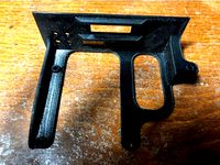
Amstrad PCW 8256/8512 keyboard legs by fdivitto
...mstrad pcw 8256/8512 keyboard legs by fdivitto
thingiverse
amstrad pcw 8256/8512 keyboard legs.
http://www.fabriziodivittorio.it
thingiverse
free
Gotek adapter for Amstrad PCW 9512 by fdivitto
...sult :-(
please read the article at:
https://fabriziodivittorio.blogspot.com/2018/05/installazione-gotek-su-amstrad-pcw-9512.html
thingiverse
free
Amstrad PCW 8256/8512 drive belt by fdivitto
...
in my tests it works perfectly.
printed using black filaflex. please look at printing settings.
http://www.fabriziodivittorio.it
thingiverse
free
Superbrain Gotek mount & bezel by RetroJonB
...e a fair bit.
please note, the pictures of the printed item are of an earlier iteration. the downloadable models are much better.
thingiverse
free

Amiga 1200 Gotek Control Center case by FerryA1
...from https://www.thingiverse.com/thing:193647
the oled screen frame part was taken from https://www.thingiverse.com/thing:3387674
thingiverse
free
3.5" floppy drive case for amstrad CPC 6128 by fujisama
... power switch
1 female db25 connector
2 switches (1 to switch from built-in driver and external drive, 1 to switch disk faces)
thingiverse
free
Gotek Floppy Emulator Carriage for Atari ST (1024STF) by PlanC
...also, you may want to move the led hole as i had to drill another. this is easily done in sketchup. file attached. good luck all.
thingiverse
free
3" Compact Floppy Disk (CF2) Drive Caddy by Tom_DD
...eet.
could be used as an external drive with the right cables (and power).
*added 5mm to the height as first upload was too short
thingiverse
free
Amiga A1012 double floppy by sgust
...them with a directly soldered 1mm pitch flat cable which can be connected through a 24 pin 2 row connector to the original cable.
Pcw
thingiverse
free
Gotek adapter for Amstrad PCW 9512 by fdivitto
...sult :-(
please read the article at:
https://fabriziodivittorio.blogspot.com/2018/05/installazione-gotek-su-amstrad-pcw-9512.html
thingiverse
free
Amstrad PCW 8256/8512 keyboard legs by fdivitto
...mstrad pcw 8256/8512 keyboard legs by fdivitto
thingiverse
amstrad pcw 8256/8512 keyboard legs.
http://www.fabriziodivittorio.it
thingiverse
free
Gotek adapter for Amstrad PCW 8256 & 8512 by fdivitto
...he pcw 8512:https://fabriziodivittorio.blogspot.it/2018/04/retro-restoring-amstrad-pcw-8512.html
http://www.fabriziodivittorio.it
thingiverse
free
Amstrad PCW 8256/8512 drive belt by fdivitto
...
in my tests it works perfectly.
printed using black filaflex. please look at printing settings.
http://www.fabriziodivittorio.it
thingiverse
free
OpenSCAD syringe plunger by DonJuanito
...plunger body length (without plunger disc nor push/base disc) pcw vertical walls...
thingiverse
free

3" Drive in 5.25" Bay Faceplate
...drive (see picture) as used on amstrad cpc, amstrad pcw sinclair spectrum +3 and possibly tatung einstein 256. it...
thingiverse
free
Superbrain Gotek mount & bezel by RetroJonB
...is a remix of: https://www.thingiverse.com/thing:2850367 "gotek adapter for amstrad pcw 8256 & 8512" and https://www.thingiverse.com/thing:2217061 "full height 5.25" to...
thingiverse
free
3" Compact Floppy Disk (CF2) Drive Caddy by Tom_DD
...drive widely used in early amstrad built machines (cpc, pcw spectrum +3) not 3.5" drives. i've replaced a few...
grabcad
free

PCW SYSTEM
...pcw system
grabcad
pcw pipeing layout system
Amstrad
3d_export
$25

ZX Spectrum 3D Model
...microcomputer pc console game atari basic z80 old vintage amstrad commodore people children toy zx spectrum 3d model fabelar...
thingiverse
free
Amstrad cartgridge parts by toinane
...amstrad cartgridge parts by toinane
thingiverse
amstrad gx4000 cartgridge remplacement parts
thingiverse
free
AMSTRAD CPC 6128 by fanto07
...amstrad cpc 6128 by fanto07
thingiverse
boitier type amstrad-cpc-6128 pour raspberry pi 3 + disque dure de 7cmx11cm.
thingiverse
free
Amstrad CPC stand - support by Sohapp65
...amstrad cpc stand - support by sohapp65
thingiverse
basic stand for amstrad cpc - 464 - 664 - 6128
thingiverse
free
Amstrad GX 4000 Everdrive Cartridge by Apes
...amstrad gx 4000 everdrive cartridge by apes
thingiverse
ein gehäuse für das everdrive vom amstrad gx 4000.
thingiverse
free

Amstrad CPC 6128 Floppy drive belt by AirGeek
...amstrad cpc 6128 floppy drive belt by airgeek
thingiverse
this is the floppy drive belt for the amstrad cpc 6128.
thingiverse
free

French mascot AMSTRAD CPC by Misterdid
...french mascot amstrad cpc by misterdid
thingiverse
enjoy
thingiverse
free
Gotek adapter for Amstrad PCW 9512 by fdivitto
...sult :-(
please read the article at:
https://fabriziodivittorio.blogspot.com/2018/05/installazione-gotek-su-amstrad-pcw-9512.html
thingiverse
free
Amstrad PCW 8256/8512 keyboard legs by fdivitto
...mstrad pcw 8256/8512 keyboard legs by fdivitto
thingiverse
amstrad pcw 8256/8512 keyboard legs.
http://www.fabriziodivittorio.it
thingiverse
free
Amstrad CPC 6128 Gotek Adapter by fdivitto
...amstrad cpc 6128, with oled.
oled position inspired by https://www.thingiverse.com/thing:2861768
http://www.fabriziodivittorio.it
Mini
turbosquid
$10
Mini Mini Luceplan
...
royalty free 3d model mini mini luceplan for download as max on turbosquid: 3d models for games, architecture, videos. (1227359)
3d_ocean
$39

Mini Cooper
...mini cooper
3docean
cabrioler cooper mini
mini cooper cabrioler
3d_export
$30

Mini lathe
...mini lathe
3dexport
mini lathe
3d_export
$5

mini mouse
...mini mouse
3dexport
mini mouse
3d_export
$5

mini house
...mini house
3dexport
mini house
3d_export
free

Mini Mecha
...mini mecha
3dexport
concept of mini mecha
3d_ocean
$20

Mini Gun
...mini gun
3docean
gatling gun gun machine gun mini gun weapon
model of a mini gatling gun.
3ddd
free

Herve mini
... кофейный , herve
http://www.mobiliavenanti.it/ru/products/hervè-mini
3d_export
$5
mini wall
...mini wall
3dexport
mini wall for living room
3d_export
$5

mini bank
...mini bank
3dexport
mini bank 3d model