Thingiverse
AiO Ender 3 Octoprint Set Up with Power and Light Remote Control by giacomo30196
by Thingiverse
Last crawled date: 3 years ago
UPDATE 28/05/2020
Some people is talking of some security flaws and even if for me it has worked flawlessly in this 2+ year, i would like to point out that i'm not responsible for any kind of damage.
I'm sorry but i don't have the time anymore to improve this project. Feel free to make a new one and with better feature/security.. if you want i'll link it in this page.
UPDATE 16/04/2019
Hi everyone, fisrt of all i'd like to apologize for my absence due to university and work, finally i'm releasing solidworks files for this project so that you can modify them as you want. I can't wait to see how you will improve everything!
Solidworks files can be found inside a zip called "SolidworksFiles.zip"
Regarding relais upgrade i'm not sure if I have the time to do it, so if anyone wants to do it and share the design, that would be amazing!
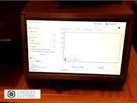
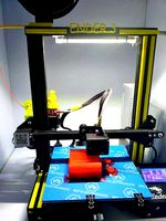
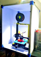
AiO Ender 3 Octoprint Set Up
Features:
Easy to set up.
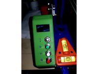
Printer on/off remote switch.
Light on/off remote switch.
Switches work with Octoprint telegram plugin.
NO CABLE MESS under the printer.
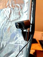
Articulated camera arm
Bill of material:
Raspberry Pi 3 with Octopi installed (https://octoprint.org/download/)
Raspberry Pi Camera V2
At least 30 cm CSI ribbon cable for the camera
LM2596 voltage regulator: https://www.amazon.it/WINOMO-regolabile-regolatore-convertitore-Step-Down/dp/B01B7BQZJK/
3 Relays !!!!!!!!!!!!!!!!!
2 XT60 Male connector
2 XT60 Female connector
2 30x30x10mm 5V Fan (but only 1 is really required)
At least 15 M3x12 screws and 11 nuts
24V led strip
USB A to mini-USB cable.
!!!!!!!!!!!!!!!!! this are those wich fit in position (https://www.amazon.it/WINGONEER-KY-019-schermo-BRACCIO-arduino/dp/B06XHJ2PBJ) but they may be UNSAFE to use for printer line. So I strongly suggest to use relays rated for at least 15Amps @ 24VDC such as theese https://www.aliexpress.com/item/30A-5V-1-Channel-Relay-Module-Board-With-Optocoupler-H-L-Level-Triger/32814917488.html?spm=2114.search0604.3.15.4aa5a460h2mb5K&ws_ab_test=searchweb0_0,searchweb201602_4_10065_10068_319_10059_10884_317_10887_10696_100031_321_322_10084_453_10083_454_10103_10618_10307_538_537_536_10134,searchweb201603_51,ppcSwitch_0&algo_expid=e76047e1-23dc-4ed4-8798-50eb01d58eb3-2&algo_pvid=e76047e1-23dc-4ed4-8798-50eb01d58eb3
wich are rated 30 Amps @ 30VDC.
Many thanks to Repraph for the suggestion.
As soon as i can i'll update the design with holes that fits into safer relays
Ok, Let's build It!
The Circuit:
The first thing to do is to make sure that the LM2596 output is 5V-5.3V once 24v is provided. (measur output voltage with a voltmeter) If not adjust voltage output by rotating the potentiometer on the board.
CONNECT THE RASPBERRY AFTER DOING THIS or you'll probably destroy it.
After this you can start doing the wiring as shown in the picture.
Note that we NEED 2 relays for the printer connection otherwise the USB cable will close the circuit even if the relay is "off" resulting in the raspberry powering printer wich is not good at all. (Believe me, i fried a raspberry and the usb port on the printer but that is another story...)
In order to avoid that problem you need to modify the USB cable: expose the 4 internal wires inside the cable and cut the red one (don't worry colors are unified so you'll always cut the 5v line, wich is what we want)
Only one fan is strictly necessary and that one is near the voltage regulator beacuse it warms up a lot.
I included a Fritzing schematics if you want to make your own modification (http://fritzing.org/home/).
The software
To make relays accessible trough Octoprint UI we actually need to tell him how to control it.
Just follow this really good tutorial made by Jeffeb3 https://www.thingiverse.com/thing:1428478 but instead of using pin GPiO23 use GPiO04.
Note that we are using pin 18 to control the printer and pin 04 to control the light.
After completing that tutorial you can test relays by plugging in the led strip and the printer.
Here is my code for those who asked:
printer_on.sh:
#!/bin/bash
gpio export 18 out
gpio -g write 18 0
printer_off.sh:
#!/bin/bash
gpio export 18 out
gpio -g write 18 1
light_on.sh:
#!/bin/bash
gpio export 18 out
gpio -g write 04 0
light_off.sh:
#!/bin/bash
gpio export 18 out
gpio -g write 04 1
/home/pi/.octoprint/config.yaml:
system:
actions:
- action: pon
command: printer_on.sh
name: PrinterOn
- action: poff
command: printer_off.sh
confirm: Are you sure you want to turn off the printer?
name: PrinterOff
- action: lon
command: light_on.sh
name: LightOn
- action: loff
command: light_off.sh
name: LightOff
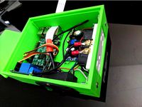
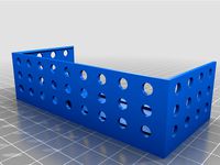
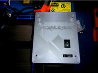
Raspberry,relays and LM2596 case
It is quite simple to put pieces together with screws. if you need any help look at the pictures.
TO FIX IN POSITION XT60 CONNECTORS JUST USE A BIT OF HOT GLUE. It's not optimal but it works really well.
The final assembly should look like this.
Now you just need to unscrew the display and slide into the chassis the whole thing.
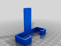
Camera arm
Same as my previous project without leds: https://www.thingiverse.com/thing:3017729
24V Led Strip Support
to be made...
If you have any doubt, do not hesitate to contact me, I'll try my best to help you.
If you like what I do and want to support me, head to https://www.paypal.com/paypalme/giacomocavasin every bit helps me to make more things for you.THANK YOU!
Some people is talking of some security flaws and even if for me it has worked flawlessly in this 2+ year, i would like to point out that i'm not responsible for any kind of damage.
I'm sorry but i don't have the time anymore to improve this project. Feel free to make a new one and with better feature/security.. if you want i'll link it in this page.
UPDATE 16/04/2019
Hi everyone, fisrt of all i'd like to apologize for my absence due to university and work, finally i'm releasing solidworks files for this project so that you can modify them as you want. I can't wait to see how you will improve everything!
Solidworks files can be found inside a zip called "SolidworksFiles.zip"
Regarding relais upgrade i'm not sure if I have the time to do it, so if anyone wants to do it and share the design, that would be amazing!
AiO Ender 3 Octoprint Set Up
Features:
Easy to set up.
Printer on/off remote switch.
Light on/off remote switch.
Switches work with Octoprint telegram plugin.
NO CABLE MESS under the printer.
Articulated camera arm
Bill of material:
Raspberry Pi 3 with Octopi installed (https://octoprint.org/download/)
Raspberry Pi Camera V2
At least 30 cm CSI ribbon cable for the camera
LM2596 voltage regulator: https://www.amazon.it/WINOMO-regolabile-regolatore-convertitore-Step-Down/dp/B01B7BQZJK/
3 Relays !!!!!!!!!!!!!!!!!
2 XT60 Male connector
2 XT60 Female connector
2 30x30x10mm 5V Fan (but only 1 is really required)
At least 15 M3x12 screws and 11 nuts
24V led strip
USB A to mini-USB cable.
!!!!!!!!!!!!!!!!! this are those wich fit in position (https://www.amazon.it/WINGONEER-KY-019-schermo-BRACCIO-arduino/dp/B06XHJ2PBJ) but they may be UNSAFE to use for printer line. So I strongly suggest to use relays rated for at least 15Amps @ 24VDC such as theese https://www.aliexpress.com/item/30A-5V-1-Channel-Relay-Module-Board-With-Optocoupler-H-L-Level-Triger/32814917488.html?spm=2114.search0604.3.15.4aa5a460h2mb5K&ws_ab_test=searchweb0_0,searchweb201602_4_10065_10068_319_10059_10884_317_10887_10696_100031_321_322_10084_453_10083_454_10103_10618_10307_538_537_536_10134,searchweb201603_51,ppcSwitch_0&algo_expid=e76047e1-23dc-4ed4-8798-50eb01d58eb3-2&algo_pvid=e76047e1-23dc-4ed4-8798-50eb01d58eb3
wich are rated 30 Amps @ 30VDC.
Many thanks to Repraph for the suggestion.
As soon as i can i'll update the design with holes that fits into safer relays
Ok, Let's build It!
The Circuit:
The first thing to do is to make sure that the LM2596 output is 5V-5.3V once 24v is provided. (measur output voltage with a voltmeter) If not adjust voltage output by rotating the potentiometer on the board.
CONNECT THE RASPBERRY AFTER DOING THIS or you'll probably destroy it.
After this you can start doing the wiring as shown in the picture.
Note that we NEED 2 relays for the printer connection otherwise the USB cable will close the circuit even if the relay is "off" resulting in the raspberry powering printer wich is not good at all. (Believe me, i fried a raspberry and the usb port on the printer but that is another story...)
In order to avoid that problem you need to modify the USB cable: expose the 4 internal wires inside the cable and cut the red one (don't worry colors are unified so you'll always cut the 5v line, wich is what we want)
Only one fan is strictly necessary and that one is near the voltage regulator beacuse it warms up a lot.
I included a Fritzing schematics if you want to make your own modification (http://fritzing.org/home/).
The software
To make relays accessible trough Octoprint UI we actually need to tell him how to control it.
Just follow this really good tutorial made by Jeffeb3 https://www.thingiverse.com/thing:1428478 but instead of using pin GPiO23 use GPiO04.
Note that we are using pin 18 to control the printer and pin 04 to control the light.
After completing that tutorial you can test relays by plugging in the led strip and the printer.
Here is my code for those who asked:
printer_on.sh:
#!/bin/bash
gpio export 18 out
gpio -g write 18 0
printer_off.sh:
#!/bin/bash
gpio export 18 out
gpio -g write 18 1
light_on.sh:
#!/bin/bash
gpio export 18 out
gpio -g write 04 0
light_off.sh:
#!/bin/bash
gpio export 18 out
gpio -g write 04 1
/home/pi/.octoprint/config.yaml:
system:
actions:
- action: pon
command: printer_on.sh
name: PrinterOn
- action: poff
command: printer_off.sh
confirm: Are you sure you want to turn off the printer?
name: PrinterOff
- action: lon
command: light_on.sh
name: LightOn
- action: loff
command: light_off.sh
name: LightOff
Raspberry,relays and LM2596 case
It is quite simple to put pieces together with screws. if you need any help look at the pictures.
TO FIX IN POSITION XT60 CONNECTORS JUST USE A BIT OF HOT GLUE. It's not optimal but it works really well.
The final assembly should look like this.
Now you just need to unscrew the display and slide into the chassis the whole thing.
Camera arm
Same as my previous project without leds: https://www.thingiverse.com/thing:3017729
24V Led Strip Support
to be made...
If you have any doubt, do not hesitate to contact me, I'll try my best to help you.
If you like what I do and want to support me, head to https://www.paypal.com/paypalme/giacomocavasin every bit helps me to make more things for you.THANK YOU!
Similar models
thingiverse
free

Relay Control OctoPrint Wanhao i3 by Jeffeb3
...print can keep on doing whatever it was doing before calling that script, wihtout waiting for the sleep or the command to finish.
thingiverse
free

Power Raspberry Pi from PSU & power printer on/off from OctoPrint by Roowan
...des and 2 screw holes.
links to components used (amazon):xt60 y splitter24v to usb 5v step down module5v one channel relay module
thingiverse
free

5v relays casing for octoprint by MC_Doomhammer
...spberry pi octoprint.
can be mounted on a v-slot or where ever u want.
no support needed
i used a skirt since im using pei sheet.
thingiverse
free

USB cable +5v Pin-1 isolator
... tool:
use the insert tool to guide the isolator into place as shown in photo and wedge it in place if possible (works sometime).
thingiverse
free
Raspberry Pi Print Controller Enclosuer by supersaiyen
...7ih6/ref=cm_sw_r_tw_dp_u_x_tmf3abhydrg74
decora outlet - https://www.amazon.com/dp/b000bwi02w/ref=cm_sw_r_tw_dp_u_x_jnf3ab42ardc5
thingiverse
free

Raspberry Pi 2 and Relay Board Enclosure for Octoprint by Help3d
...board. no more messy cables around the 3d printer.
i use the relay board to switch on/off off the printer remotely. very useful!
thingiverse
free

Relay case / HiLetGo 1 channel relay
...ill out to a larger size if desired.
i've included the editable files as well if you need to make changes to it.
have fun!!
thingiverse
free

Arcade Button Frame by protospork
... shell scripts, to gpio inputs.
the buttons are just momentary switches and they're pretty cheap and reasonably good looking.
thingiverse
free
Raspberry Pi Zero W + 30A relay module Octoprint case by steelpuxnastik
...or mounting on ender 3 psu (or wherever you want) to control prints and printer shutdown after prints or in case of emergencies.
thingiverse
free

Octoprint automation led lights by Domo-Com
... ws2812 5050 driven with an arduino nano...
-i order also step by step motors to drive (or try :) my pi camera with octoprint ;)
Giacomo30196
thingiverse
free

Turnigy 9XR PRO Thumb Sticks by giacomo30196
...i do and want to support me, head to https://www.paypal.me/giacomo30196 every bit helps me to make more things for you.thank you!
thingiverse
free

Ender 3 Raspberry Pi 2,5mm fan Remixed from giacomo30196 by Phede
...ender 3 raspberry pi 2,5mm fan remixed from giacomo30196 by phede
thingiverse
for cura user scale it down to 10%
thingiverse
free

Ender 3 RasPi Cam V2 articulated arm with Led stand by giacomo30196
...i do and want to support me, head to https://www.paypal.me/giacomo30196 every bit helps me to make more things for you.thank you!
thingiverse
free

Ender 3 Raspberry Pi 2/3 mount WITHOUT RAIL
...rail to mount it on another printer. thank's to giacomo30196 for the original...
thingiverse
free

Ender 3 Raspberry Pi 2/3 mount (UPDATED V2) by giacomo30196
...i do and want to support me, head to https://www.paypal.me/giacomo30196 every bit helps me to make more things for you.thank you!
thingiverse
free

Ender-3 (and Pro) Bed handle with ball joint mount for Raspberry Pi Camera
...mount added to work with https://www.thingiverse.com/thing:3017729. thanks to users giacomo30196 and...
thingiverse
free

Ender 3 Raspberry Pi 2/3 mount (2 rails)
...mount (2 rails) thingiverse this design is inspired by giacomo30196#39;s https://www.thingiverse.com/thing:3016364. a two rails design make this case more...
thingiverse
free

Raspberry Pi 3 40mm fan case by jHit
...pi 2/3, based on the great mount case from giacomo30196 i have removed every gpio/camera holes and centered the...
grabcad
free

OctoPi case with Camera holder
...raspi cam v2 articulated arm with led stand by giacomo30196 on thingiverse: https://www.thingiverse.com/thing:3017729 i have not made any changes...
Aio
turbosquid
$59

eGo Aio
... available on turbo squid, the world's leading provider of digital 3d models for visualization, films, television, and games.
turbosquid
$3

AIO table bench chair
... available on turbo squid, the world's leading provider of digital 3d models for visualization, films, television, and games.
3d_ocean
$59

VRay Building Materials S02 - AIO for C4D
... with vray building materials s02 materials library for cinema 4d. this is all in one material library for my building materia...
3d_ocean
$19

10 x Hi-Res Porcelain Textures - AIO
...f my series of 10 floral porcelain/ceramic textures. all textures are hi-res custom made textures and can be used for ceramic,...
3d_ocean
$19

25 Standard Liquids Materials Pack AIO for C4D
...is all-in-one material library of my series of 2 cinema 4d standard liquid materials series. it contains 25 standard liquid ma...
turbosquid
$39

E3D - HP Elite One 1000 G1 AiO 34 inches model
...1000 g1 aio 34 inches model for download as max, obj, and c4d on turbosquid: 3d models for games, architecture, videos. (1245758)
3d_ocean
$30

121 Standard Ground/Terrain Materials-AIO for C4D
...n: this is all-in-one material library of my series of 8 cinema 4d standard ground/terrain materials series. it contains 121 s...
3d_ocean
$55

Standard Clothes Material Pack-AIO for Cinema 4D
...ll-in-one material library of my series of 6 cinema 4d standard clothes materials libraries. it contains 94 standard cloth mat...
3d_ocean
$89

171 Standard Stone Materials Pack AIO for C4D
...s all-in-one material library of my series of 10 cinema 4d standard stone materials library series. it contains 171 standard s...
3d_ocean
$75

114 Standard FX Materials Pack AIO for Cinema 4D
...ll-in-one material library of my series of 8 cinema 4d standard fx materials series. it contains 114 standard fx materials. i ...
Octoprint
thingiverse
free

Octoprint Case + Relais by bennylu
...octoprint case + relais by bennylu
thingiverse
octoprint case+ doppel relais
thingiverse
free
Octoprint Control-Panel by sanisam
...von: https://plugins.octoprint.org/plugins/display_panel/?utm_medium=announcements&utm_source=octoprint&utm_content=1.5.2
thingiverse
free
Octoprint Controller by CandlerCustoms
...control. it's super handy.
check out my post about it here: http://www.candlercustoms.com/3d-printed-octoprint-controller/
thingiverse
free

Octoprint Raspberry Pi Logo by ProtomakerSprint
...octoprint raspberry pi logo by protomakersprint
thingiverse
octoprint raspberry pi logo
thingiverse
free

Octoprint plugin - DisplayLayerProgress
...o the plug inhttps://github.com/ollisgit/octoprint-displaylayerprogresshttps://github.com/ollisgit/octoprint-displaylayerprogress
thingiverse
free

OctoPrint Wifi Display by Nori0aw
...it on character lcd screen (20x4).
boards:
esp8266
lcd screen (20x4)
source code: https://github.com/nori0aw/octoprintwifidisplay
thingiverse
free

Octoprint Logo Molle by oiitsame
...octoprint logo molle by oiitsame
thingiverse
thingiverse
free

OctoPrint Statue by KingRahl
...ng octoprint free and available for anyone to use.
a special thanks to janina himmen (@zwergimbikini on twitter) for the design.
thingiverse
free
Case Octoprint (for Raspberry, DC/DC converter and Relay) In file list "Octoprint" is correct! by Genna1986
...ot; is correct! by genna1986
thingiverse
case for raspberry, relay board and dc/dc converter... all you need to use octoprint...
thingiverse
free
Octoprint Ultimaker holder by klenk
...my simple design for attaching my octoprint server to my ultimaker.
raspberry case used: http://www.thingiverse.com/thing:1015706
Remote
archibase_planet
free

Remote
...remote
archibase planet
tv remote remote controller remote
remote - 3d model for interior 3d visualization.
archibase_planet
free

Remote
...e
archibase planet
remote control remote controller remote
remote n140512 - 3d model (*.gsm+*.3ds) for interior 3d visualization.
turbosquid
$1

Remote
...
turbosquid
royalty free 3d model remote for download as obj on turbosquid: 3d models for games, architecture, videos. (1487515)
3d_export
$5

Tv Remote
...tv remote
3dexport
tv remote
3d_ocean
$7

Remote controller
... control switcher tv remote
remote controller for tv, sound systems etc easy to edit textures photo real rendered with mental ray
turbosquid
$39

remote
...free 3d model remote for download as obj, fbx, blend, and dae on turbosquid: 3d models for games, architecture, videos. (1387531)
turbosquid
$5

remote
...free 3d model remote for download as 3ds, obj, fbx, and blend on turbosquid: 3d models for games, architecture, videos. (1401849)
archive3d
free

Remote 3D Model
...l
archive3d
tv remote remote controller remote
remote - 3d model for interior 3d visualization.
turbosquid
$11
Remote
... available on turbo squid, the world's leading provider of digital 3d models for visualization, films, television, and games.
turbosquid
$10

remote
... available on turbo squid, the world's leading provider of digital 3d models for visualization, films, television, and games.
Ender
3ddd
$1
Enders / Elegance
...enders / elegance
3ddd
обогреватель
уличный газовый обогреватель enders elegance
высота: 2200 мм
3d_export
free
ender 3 frame cavity covers
... of the creality ender 3 - makes it look a bit more attractive it just slides into the open channels of the aluminium framework
turbosquid
$1
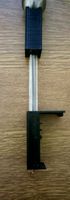
pen support for ender 3
...y free 3d model pen support for ender 3 for download as blend on turbosquid: 3d models for games, architecture, videos. (1611282)
3d_ocean
$9
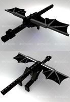
Ender Dragon Minecraft
...ojang obj poly videogames
ender dragon minecraft created with cinema 4d r15 formats included: max 2013 – fbx 2012 – c4d r15 – obj
3d_export
free
Creality ender enclosure webcam mount
...e creality enclosure. sure is better than a tripod. change it up if it helps. i printed pla with 50% infill on my dd ender 3 pro.
3d_export
free
ender 3 enclosure corners
...er corners and 4 upper corners, using 25mmx25mm angled aluminium pieces that gets covered on inside of the frame with plexiglass
3d_export
free
ender 3 3d print bed clips
...ed + normal aluminium bed frame of the creality ender 3 = 6mm (b) these clips are designed for glass plate + aluminium bed = 4mm
3d_export
$5
GRUMPY CAT
...grumpy cat 3dexport grumpy cat to print in ender ...
3d_export
$5

Logs fire
...with one multi material for corona and vray r ender. albedo, normal, uvmap, roughness format jpg 4096x4096 models:...
3d_export
$42

excavator
...is the original size. 0.12 mm printing surface creality ender5 ...
Control
3d_ocean
$4
Controller TQFP32
...qfp32
3docean
chip controller cpu electronic gpu mcu micro controller silicon smd tqfp wafer
a micro controller in tqfp32 package
3d_ocean
$4
Controller TQFP44
...44
3docean
chip controller cpu electronic gpu mcu micro controller package smd tqfp tqfp44
a micro controller in a tqfp44 package
3d_export
$15
control unit
...control unit
3dexport
control unit
3ddd
$1
Yacht control
...yacht control
3ddd
yacht control
3d_export
$5
controle pgdm
...controle pgdm
3dexport
carcaca controle pgdm
turbosquid
free

controler
... available on turbo squid, the world's leading provider of digital 3d models for visualization, films, television, and games.
3ddd
$1

Control
...
http://www.schmitz-leuchten.de/html-ru/einzelleuchten-lampentyp-details.php?lamptype_no=700&group;=917&id;=731
3d_ocean
$4
Controller TQFP100
...100
3docean
chip computer cpu electronic gpu mcu micro controller pin platine silicon wafer
a micro controller in tqfp100 package
3d_ocean
$4
Controller TQFP64
...qfp64
3docean
chip computer cpu gpu mcu micro controller package silicon tqfp tqfp64 wafer
a micro controller in a tqfp64 package
3d_ocean
$7
Remote controller
... control switcher tv remote
remote controller for tv, sound systems etc easy to edit textures photo real rendered with mental ray
Power
turbosquid
$100

power
...ower
turbosquid
royalty free 3d model power for download as on turbosquid: 3d models for games, architecture, videos. (1421990)
3d_export
$5

Power
...power
3dexport
3d_export
$5
power outlets
...power outlets
3dexport
power outlets
3ddd
$1
lion power
...lion power
3ddd
лев , статуя
lion power gold sculpture
3ddd
$1

Sea Power
...
компас , море , часы
часы с компасом sea power
3ddd
free
Meridiani / Power
...power
3ddd
meridiani , круглый
стол power производитель meridiani, диаметр 120,высота 67
3d_export
$5

Power Surge
...power surge
3dexport
the power surge is a all mesh carnival ride to lower in game part count and lag
turbosquid
$8
Airport Ground Power Unit (AXA Power )
... available on turbo squid, the world's leading provider of digital 3d models for visualization, films, television, and games.
turbosquid
$50

Power Houser
...rbosquid
royalty free 3d model power houser for download as on turbosquid: 3d models for games, architecture, videos. (1333800)
3d_export
$5

power outlet
...power outlet
3dexport
power outlet<br>format file maya 2018, 3d max 2017, obj, fbx
Light
archibase_planet
free
Light
...light
archibase planet
lamp lighting light
light - s2 - 3d model for interior 3d visualization.
archibase_planet
free
Light
...light
archibase planet
light luminaire lighting
light l0465 - 3d model (*.gsm+*.3ds) for interior 3d visualization.
3d_export
$5
lighting
...lighting
3dexport
lighting
3d_export
$5

lighting
...lighting
3dexport
lighting in livingroom
turbosquid
$3

Lighting Tree with Lights
...d model lighting tree with lights for download as max and 3ds on turbosquid: 3d models for games, architecture, videos. (1585507)
archibase_planet
free
Light
...light
archibase planet
luster lighting solution
light - s - 3d model for interior 3d visualization.
archibase_planet
free
Light
...light
archibase planet
luster lamp lighting
light 1 - 3d model for interior 3d visualization.
archibase_planet
free
Lights
...lights
archibase planet
surgical lights surgical lamp
surgical lights (floor) - 3d model for interior 3d visualization.
archibase_planet
free
Light
...light
archibase planet
lighting luminaire candlelight
light l0463 - 3d model (*.gsm+*.3ds) for interior 3d visualization.
3d_export
$18
street light-lighting-light-xia bing
...
3dexport
street light-lighting-light-xia bing<br>max 2015 v-ray 3 max 2015<br>textures<br>all files in zip...
Set
archibase_planet
free

Setting
...setting
archibase planet
setting cover place setting
setting - 3d model (*.gsm+*.3ds) for interior 3d visualization.
archibase_planet
free
Setting
...setting
archibase planet
setting place setting cover
setting - 3d model (*.gsm+*.3ds) for interior 3d visualization.
archibase_planet
free

Setting
...setting
archibase planet
setting place setting cover
setting - 3d model (*.gsm+*.3ds) for interior 3d visualization.
3d_export
$8

decorative set mens set
...decorative set mens set
3dexport
decorative set men's set
archibase_planet
free
Set
...anet
set kitchen ware kitchen set kitchen tools
set kitchen tools n281114 - 3d model (*.gsm+*.3ds) for interior 3d visualization.
archibase_planet
free

Set
...set
archibase planet
beer set bar equipment
beer set - 3d model for interior 3d visualization.
archibase_planet
free

Set
...set
archibase planet
cover place setting
set - 3d model (*.gsm+*.3ds) for interior 3d visualization.
archibase_planet
free

Set
...set
archibase planet
kitchen set kitchen ware
set - 3d model (*.gsm+*.3ds) for interior 3d visualization.
archibase_planet
free
Set
...set
archibase planet
set cup glass kitchen ware
set - 3d model (*.gsm+*.3ds) for interior 3d visualization.
archibase_planet
free

Set
...set
archibase planet
flatware cover place setting
set n311210 - 3d model (*.gsm+*.3ds) for interior 3d visualization.
3
turbosquid
$10
Mountain Bike 3 -3 of 3
...model mountain bike 3 (#3 of 3) for download as fbx and blend on turbosquid: 3d models for games, architecture, videos. (1438752)
turbosquid
$6

Rock 3-3
...urbosquid
royalty free 3d model rock 3-3 for download as obj on turbosquid: 3d models for games, architecture, videos. (1628065)
turbosquid
$29
Books 150 pieces 3-3-3
...books 150 pieces 3-3-3 for download as max, obj, fbx, and stl on turbosquid: 3d models for games, architecture, videos. (1384033)
turbosquid
$3

Genesis 3 Clothing 3
... available on turbo squid, the world's leading provider of digital 3d models for visualization, films, television, and games.
3d_export
$5
hinge 3
...hinge 3
3dexport
hinge 3
3ddd
$1
Розетка 3
...розетка 3
3ddd
розетка
розетка 3
turbosquid
$50

is-3
... available on turbo squid, the world's leading provider of digital 3d models for visualization, films, television, and games.
turbosquid
$10

Mountain Bike 3 -2 of 3
...model mountain bike 3 (#2 of 3) for download as fbx and blend on turbosquid: 3d models for games, architecture, videos. (1438750)
turbosquid
$10
Mountain Bike 1 -3 of 3
...model mountain bike 1 (#3 of 3) for download as fbx and blend on turbosquid: 3d models for games, architecture, videos. (1438743)
3d_export
$5

3 CATS
...3 cats
3dexport
3 cats pen holder