Thingiverse
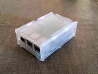
Acrylic Case for ThingOMatic (TOM) by evanevery
by Thingiverse
Last crawled date: 3 years ago
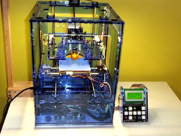
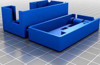
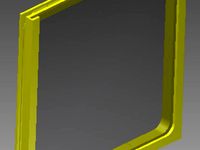
I'm not a big fan of the wood case for the TOM and I wanted to make one out of Acrylic. I found the very nice case that BuiltToSpec did ( http://www.thingiverse.com/thing:11641 ) but I wanted a case built on the latest case design. BuiltToSpec's was based on the older case which had the side mounted fan, I wasn't sure what other changes had been implemented in the latest design, and I was pretty sure I would have to make a good deal of adjustments to support my actual Acrylic thickness. So I just started with the latest official TOM case drawings. I did use BuiltToSpec's idea to stress relieve the corners of the nut slots though - kudo's for that thought!
Anyway, the attached drawings were modified to work with the 1/4 Inch Acrylic I could source. I waited until the Acrylic actually arrived and then measured its thickness. As others will attest, the thickness of 1/4 inch Acrylic can vary a lot between manufacturers and I even saw a pretty good variation in one corner of the single 4x8 sheet I had cut down to use! If you want to do an Acrlic case, I suggest you get the Acrylic first and measure its thickness precisely before you start cutting stuff!
The 1/4" Acrylic I used had a nominal thickness of about .225 inch (5.73mm). I did have one corner of the sheet exceed 6mm though so a couple of parts had to be re-cut from a different sub-panel.
All three of the original drawings (Makerbot, Gen4 Interface, and Mk6 Extruder) were modified as follows:
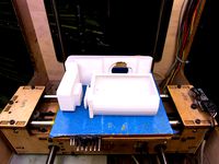
Tabs/Slots: Modified to accommodate 5.7mm Acrylic. All Tabs were lengthened (from 5.5 to 5.9 mm), All Slots were widened (from 5.5 to 5.9mm), All screw holes re-centered to the new slot centerlines, and stress relief was added to the bottom corners of all the nut slots to help prevent cracking under stress.
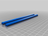
Dimensions were adjusted were necessary to accommodate the increased thickness of the Acrylic where appropriate. (i.e. In order to maintain proper fitment of the steel X/Y/Z axis rods the outside dimension of case and axis platforms had to be maintained)
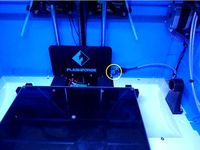
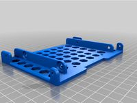
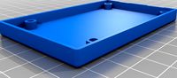
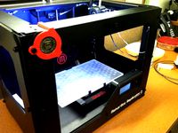
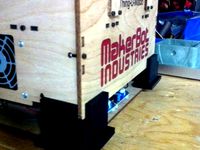
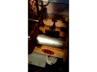
I'm using a different power supply than the one provided with the original unit. (The original one died and I wanted to use one with a bit more power). Unfortunately MOST power supplies DO NOT pull air through the cable side of the power supply - they pull air from the bottom of the power supply. This therefore requires a large hole on the underside of the TOM to provide airflow through the P/S, and it also is a good idea to provide some other means to ventilate the electronics bay. I added a large hole to the electronics panel to line up with the air intake on my new P/S. I also added mounting points for 40mm fans on both sides of the P/S to help ventilate the bay (since the P/S wouldn't be doing that). If you don't need/want these mods, just delete the associated entities!
I added a several slots up the back side of the case to allow threading zip ties to secure wires as they go up the back corners. I used the existing "notches" in the design, and mirrored them as needed to maximize symmetry. (I have no idea why there were notches in the original design)
I also wanted to accommodate a couple of other public mods at the same time:
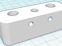
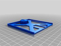
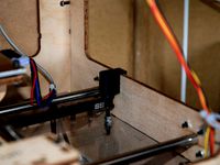
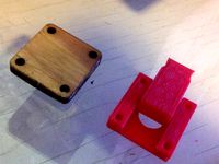
I modified the X-Axis drive support to optionally allow use of the X-Axis Follower Mod ( http://www.thingiverse.com/thing:8163 ). I added two holes to the support and one to each of the clamping pieces. The change works equally well with the original design as well as the follower mod.
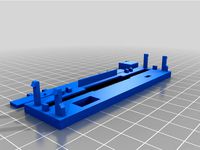
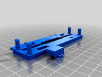
I modified the Z axis arms to allow use of my modular extruder connector brackets. This allows electrical connectors to be implemented for quick change of the extruder (1.75 -> 3mm -> PLA -> Mk6 -> Mk7, etc) without having to get into the electronics bay ( http://www.thingiverse.com/thing:13260 ). I also modified the Z-Axis arms so that the design would allow the attachment of the emergency thermal cutoff board without any drilling. There were a couple of holes already in place on the existing arm drawing but I'm not sure what they were supposed to fit (maybe a different thermal cutoff board), so I left them in place and added another hole so the board I have would also fit. I then added two holes in the arm for my connector bracket. I updated the one arm already in the design to allow connection of the thermal cutoff board, and then added a completely new optional arm to the drawing if you want to use the connector bracket. The Z-Axis arms are completely interchangeable so you can choose any two you want and cut them - they can be used on either side...
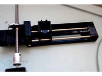
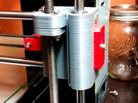
I provided a couple of optional Y-Axis parts to allow use of the X Stage Idler Tension Mod ( http://www.thingiverse.com/thing:8189 ). The use of this mod will require a different Y-Axis TOP (with slot cut so the idler axle screw head can slide back and forth under the tensioner), a hole for the tensioner screw to run through the right side panel, and the tabs on the top of the right side panel to be removed. The original parts (modified for 5.7mm) are in the drawing, but I've also included the two parts updated with the additional necessary modifications if you want to use this really nice mod. (Be aware that the 0.4 mm increased thickness of each acrylic side made the Y-Axis interior distance a little bit narrower so you will either want to decrease the design width of the tensioner by about .5mm on each side or just sand each tensioner side a bit to narrow it up - about until you reach the steel rod holes - as I did).
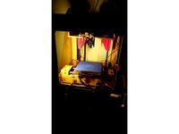
I added some LED strip lighting to the top of my case, but that is nothing that needed any mods to the design.
Anyway, the attached drawings were modified to work with the 1/4 Inch Acrylic I could source. I waited until the Acrylic actually arrived and then measured its thickness. As others will attest, the thickness of 1/4 inch Acrylic can vary a lot between manufacturers and I even saw a pretty good variation in one corner of the single 4x8 sheet I had cut down to use! If you want to do an Acrlic case, I suggest you get the Acrylic first and measure its thickness precisely before you start cutting stuff!
The 1/4" Acrylic I used had a nominal thickness of about .225 inch (5.73mm). I did have one corner of the sheet exceed 6mm though so a couple of parts had to be re-cut from a different sub-panel.
All three of the original drawings (Makerbot, Gen4 Interface, and Mk6 Extruder) were modified as follows:
Tabs/Slots: Modified to accommodate 5.7mm Acrylic. All Tabs were lengthened (from 5.5 to 5.9 mm), All Slots were widened (from 5.5 to 5.9mm), All screw holes re-centered to the new slot centerlines, and stress relief was added to the bottom corners of all the nut slots to help prevent cracking under stress.
Dimensions were adjusted were necessary to accommodate the increased thickness of the Acrylic where appropriate. (i.e. In order to maintain proper fitment of the steel X/Y/Z axis rods the outside dimension of case and axis platforms had to be maintained)
I'm using a different power supply than the one provided with the original unit. (The original one died and I wanted to use one with a bit more power). Unfortunately MOST power supplies DO NOT pull air through the cable side of the power supply - they pull air from the bottom of the power supply. This therefore requires a large hole on the underside of the TOM to provide airflow through the P/S, and it also is a good idea to provide some other means to ventilate the electronics bay. I added a large hole to the electronics panel to line up with the air intake on my new P/S. I also added mounting points for 40mm fans on both sides of the P/S to help ventilate the bay (since the P/S wouldn't be doing that). If you don't need/want these mods, just delete the associated entities!
I added a several slots up the back side of the case to allow threading zip ties to secure wires as they go up the back corners. I used the existing "notches" in the design, and mirrored them as needed to maximize symmetry. (I have no idea why there were notches in the original design)
I also wanted to accommodate a couple of other public mods at the same time:
I modified the X-Axis drive support to optionally allow use of the X-Axis Follower Mod ( http://www.thingiverse.com/thing:8163 ). I added two holes to the support and one to each of the clamping pieces. The change works equally well with the original design as well as the follower mod.
I modified the Z axis arms to allow use of my modular extruder connector brackets. This allows electrical connectors to be implemented for quick change of the extruder (1.75 -> 3mm -> PLA -> Mk6 -> Mk7, etc) without having to get into the electronics bay ( http://www.thingiverse.com/thing:13260 ). I also modified the Z-Axis arms so that the design would allow the attachment of the emergency thermal cutoff board without any drilling. There were a couple of holes already in place on the existing arm drawing but I'm not sure what they were supposed to fit (maybe a different thermal cutoff board), so I left them in place and added another hole so the board I have would also fit. I then added two holes in the arm for my connector bracket. I updated the one arm already in the design to allow connection of the thermal cutoff board, and then added a completely new optional arm to the drawing if you want to use the connector bracket. The Z-Axis arms are completely interchangeable so you can choose any two you want and cut them - they can be used on either side...
I provided a couple of optional Y-Axis parts to allow use of the X Stage Idler Tension Mod ( http://www.thingiverse.com/thing:8189 ). The use of this mod will require a different Y-Axis TOP (with slot cut so the idler axle screw head can slide back and forth under the tensioner), a hole for the tensioner screw to run through the right side panel, and the tabs on the top of the right side panel to be removed. The original parts (modified for 5.7mm) are in the drawing, but I've also included the two parts updated with the additional necessary modifications if you want to use this really nice mod. (Be aware that the 0.4 mm increased thickness of each acrylic side made the Y-Axis interior distance a little bit narrower so you will either want to decrease the design width of the tensioner by about .5mm on each side or just sand each tensioner side a bit to narrow it up - about until you reach the steel rod holes - as I did).
I added some LED strip lighting to the top of my case, but that is nothing that needed any mods to the design.
Similar models
thingiverse
free
iron3d x-end modified by BloodBeard
...the use of and idler arm and screw/nut to provide better belt tension than the slot on the metal bar that runs across the x-axis.
thingiverse
free
Monoprice Select Mini. X Axis Belt Tensioner Mod. by lowfat
...sm w/o an x-axis shroud is normal. so i've added versions that you can use that don't require the shroud to be installed.
thingiverse
free

Smootiebox - slim - dumle-remix by Duckle
...ustomizer, and allow the user to specify custom fan sizings, if they want fans or not, and if they want the vslot mounting holes.
thingiverse
free

Clear Acrylic BeagleBone Case with Air Vents by paulctan
...ospec's version. i have added the ventilation holes and changed it to use 4-40 tapped holes instead of needing 4 extra nuts.
thingiverse
free
Z Axis Mod for FlashForge Inventor I by jynclr
... added stls for 3mm, 4mm, 5mm, and 6mm thicknesses. the glass bed in the photos is 3mm thick so i have the arm for 3mm thickness.
thingiverse
free
Stacking Pi 2 case by Yngel
...cking cases with cameras or screens or other i/os possible. use 3mm thick material, like the acrylic in the pics, for a snug fit.
thingiverse
free
5.25 to 3.5 2.5 HDD SSD adapter by DC010
...u might be able to stack 2 of these in 1 slot, but i found at least 1 case that it didn't, so you can check that on your own.
thingiverse
free
Prusa i3 Belt Tesnioning Kit by jonmessenger
... it fit perfectly without any cleanup at all.
i should also note that you will loose about 16 mm on the x axis because of this.
thingiverse
free
Ender 3 Pro Y-Axis Slot Insert by ZachAllen11
...'m not sure about the ender 3, as the frame is different and i don't own one or know where to find reliable measurements.
thingiverse
free
OctoPi Case V-Slot Mount by aaronroma
...t, print two of the m3 t-nuts. you will then need 2 m3 nuts to press fit into the t-nuts. you will also need 2 m3 x 6mm bolts.
Evanevery
thingiverse
free
ZoomFloppy Box by evanevery
...zoomfloppy box by evanevery
thingiverse
a simple box to protect your zoomfloppy board!
thingiverse
free
FC5025 enclosure by evanevery
...erse
this is a box/enclosure for the fc5025 usb/floppy controller. its a simple design of two halves held together by 2 screws.
thingiverse
free
StalkBox by evanevery
...r, and sd card interface: http://garden.seeedstudio.com/seeeduino_stalker_v2.0 ). the project includes both the box and a cover.
thingiverse
free
Kryoflux Case by evanevery
...'m not a fan of snap together boxes so this enclosure is held together with four #3 screws up from the underside of the base.
thingiverse
free

SuperCard Pro Enclosure by evanevery
...his is a box/enclosure for the supercard pro usb/floppy controller. its a simple design of two halves held together by 4 screws.
thingiverse
free
Teac Floppy Faceplate by evanevery
...al face plate. the "legs", "button", and penetrations have been modified to work with the teac floppy drive.
thingiverse
free
piZero pi1541 Enclosure by evanevery
... held together with a single #4 x 1-1/4 screw. optionally, you can also use 4 short #3 screws up from the underside of the base.
thingiverse
free
3.5 Floppy Disk Cleaning Bracket and Knob by evanevery
...to rotate a 3.5 inch floppy disk and hold the shutter open at the same time so i could wipe it with an alcohol swab. here it is!
thingiverse
free
Floptical Faceplate by evanevery
...al dimensions, button, door, and led placement and have compared this favorably with alps, panasonic, and sony drive face plates.
thingiverse
free

pi1541 Box by evanevery
... enclosures so this one uses #4 screws to hold it together. #4 x 1" inch will work but #4 x 1-1/4 or 1-1/2 would be better!
Thingomatic
thingiverse
free
Thingomatic Panel Holder by MrSimonBrooks
... parts inspired by thingiverse.com/thing:27865 for the replicator will help anyone in a similar situation with their thingomatic.
thingiverse
free
Replicator 2 Makerbot ThingOMatic Coin Holder by Tunell
...ic coin holder by tunell
thingiverse
bracket to hold your precious makerbot thingomatic coin from back in the good ol' days.
thingiverse
free
Thingomatic Feet by michael_gailling
...c)
v3 - hollow (takes more time but uses less and is lighter)
edit: if you make a derivative please attribute the original to me.
thingiverse
free
Thingomatic Heater Board v1.1 by MakerBot
...not least, the pcb includes a header for connecting it to the rest of the makerbot electronics so that you can easily wire it up.
thingiverse
free
Thingomatic Corner Light by MakeItWithCalvin
...ng!
this can also be used in any application where you want a light in a corner and have the light aimed out at a 45* angle too.
thingiverse
free
Thingomatic rod end plates by mklintott
...ere starting to deform and i was getting a lot of noise as a result. these fit perfectly and seriously cut down on machine noise.
thingiverse
free
Idle Guard, Thingomatic Y-axis by LukeChilson
...you haven't installed a drag chain and/or do a lot of hacking on your bot i highly recommend installing this on your machine.
thingiverse
free
Thingomatic Low Profile Belt Clamp by MakeItWithCalvin
... looks much sleeker.
i printed mine in proto-pasta carbon fiber filament at 100% infill strictly to make it as stiff as i could.
thingiverse
free
Thingomatic y-axis Endcaps by MacaroniNgineer
...uickly removed without having to unscrew 8 fasteners to get them out. packaged as a plate for the tom with 2 endcaps and 2 shims.
thingiverse
free
ThingOMatic 1KG Filament Spool Holder by davepix
...ingiverse.com/thing:10463 adding a locking insert to hold together the two pieces as i wanted to be able to build it on the tom.
Tom
turbosquid
$30

Toy tom tom
...turbosquid
royalty free 3d model tom tom for download as c4d on turbosquid: 3d models for games, architecture, videos. (1354523)
turbosquid
$10

Tom Tom Drum
... available on turbo squid, the world's leading provider of digital 3d models for visualization, films, television, and games.
turbosquid
$5
Tom-Tom Drum
...tom drum for download as blend, blend, 3ds, dae, fbx, and obj on turbosquid: 3d models for games, architecture, videos. (1593415)
3ddd
$1
tom dixon
...tom dixon
3ddd
tom dixon
торшер tom dixon
3ddd
free

Tom Dixon
...tom dixon
3ddd
tom dixon
торшер tom dixon
3ddd
$1

Tom Dixon
...tom dixon
3ddd
tom dixon , fin
fin light by tom dixon
3ddd
$1
Tom Dixon
...tom dixon
3ddd
tom dixon , fin
tom dixon fin light blue
3ddd
$1

Tom Dixon
...tom dixon
3ddd
dixon , tom
size 27x39
turbosquid
$15
floor lamp drum tom tom
... available on turbo squid, the world's leading provider of digital 3d models for visualization, films, television, and games.
3ddd
$1

Tom Dixon
...tom dixon
3ddd
tom dixon
дизайнер: tom dixon
люстра beat light tall
люстра beat light wide
люстра beat light fat
Acrylic
turbosquid
$15
Acrylic Lectern For The Chruch - Podium Acrylic
...the chruch - podium acrylic for download as skp, obj, and 3ds on turbosquid: 3d models for games, architecture, videos. (1642137)
3ddd
free
Acrylic bathtub
...acrylic bathtub
3ddd
ванна
acrylic bathtub. size 170x110 cm
turbosquid
$24
Acrylic Stool
...3d model acrylic stool for download as 3ds, max, obj, and fbx on turbosquid: 3d models for games, architecture, videos. (1311388)
turbosquid
$9
Acrylic Tables
... available on turbo squid, the world's leading provider of digital 3d models for visualization, films, television, and games.
turbosquid
$9
Acrylic Chair
... available on turbo squid, the world's leading provider of digital 3d models for visualization, films, television, and games.
turbosquid
$5

Acrylic Chair
... available on turbo squid, the world's leading provider of digital 3d models for visualization, films, television, and games.
turbosquid
$3
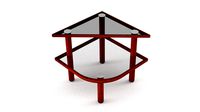
Table acrylic
... available on turbo squid, the world's leading provider of digital 3d models for visualization, films, television, and games.
3d_export
$5
Acrylic bath
... empire. originally created in 3ds max 2021 and v-ray next. materials v-ray mtl rubber; chromium; acrylic. modifiers: turbosmooth
3ddd
$1
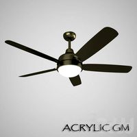
Acrylic GM
...acrylic gm
3ddd
вентилятор
model is available in retail fanstar
3d_export
$17

Acrylic Chair 3D Model
...acrylic chair 3d model
3dexport
chair furniture acrylic
acrylic chair 3d model shalasaska 7623 3dexport
Case
3d_export
$1
case
...case
3dexport
case
archibase_planet
free
Case
...case
archibase planet
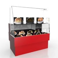
showcase show-case glass case
glass-case + cakes - 3d model for interior 3d visualization.
archibase_planet
free
Case
...case
archibase planet
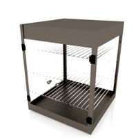
showcase show-case glass case
glass-case for chips - 3d model for interior 3d visualization.
archibase_planet
free
Case
...case
archibase planet
case shelving drawer
case - 3d model for interior 3d visualization.
archibase_planet
free
Case
...case
archibase planet
case rack locker
case - 3d model for interior 3d visualization.
archibase_planet
free
Case
...case
archibase planet
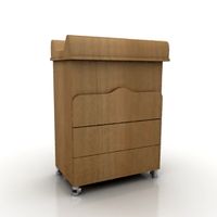
case drawer kitchen furniture
case - 3d model for interior 3d visualization.
archibase_planet
free
Case
...case
archibase planet
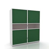
case cupboard shelving
glass case - 3d model for interior 3d visualization.
archibase_planet
free
Case
...case
archibase planet
case handbag suitcase
case - 3d model (*.gsm+*.3ds) for interior 3d visualization.
archibase_planet
free
Case
...case
archibase planet
case suitcase
case 5 - 3d model (*.gsm+*.3ds) for interior 3d visualization.
archibase_planet
free
Case
...case
archibase planet
locker case dresser
case - 3d model (*.gsm+*.3ds) for interior 3d visualization.