Thingiverse
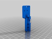
8mm Inductive Sensor Mount by Superflex_Plastic_Fantastic
by Thingiverse
Last crawled date: 3 years ago
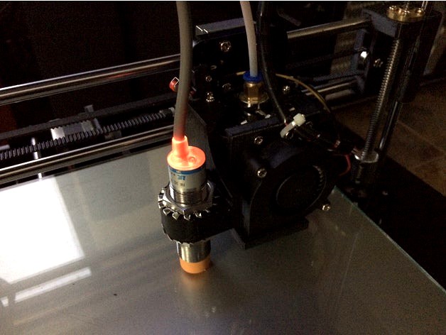
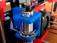
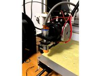
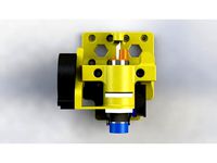
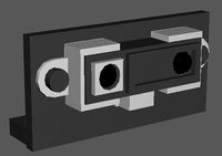
Mount for an 8mm inductive sensor designed to fit a Tronxy P802E.
A description on firmware set up and calibration is posted below the part description here.
Offsets are X-55, Y-26. This design allows for mounting the sensor in close proximity to the bed as aluminum used in the construction of the heated bed reduces the design range of the sensor considerably. With this design I am able to use the 8mm sensor with a glass build plate on the original supplied bed with minor allowances for it to clear the print. The design also conforms to physical requirements of the carriage assembly my Tronxy P802E came with. Additionally use of angles and curves allows it to be printed without the requirement for support material.
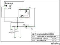
I am reasonably convinced any combination of sensor be it PNP, NPN, NO or NC can be wired into a controller by use of various settings, voltage dividers, mosfets and/or diodes to make them operable. For various reasons in my application I elected to use the following sensor:
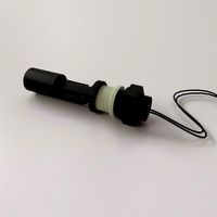
LJ18A3-8-Z/BX 8mm Approach Sensor Inductive Proximity NPN NO Switch DC 6-36V LW
For my application the sensor is powered from the main 12VDC supply voltage to ensure operation within the sensor's design range. The sensor offers sufficient sensitivity to operate with an aluminum bed and will allow for the use of a glass build plate. On my Tronxy P802E, a 5VDC active-lo signal is supplied via the board's own Z end stop header pin to the Z end stop frame mounted micro switch and signal is sent through the NO micro switch to the Z end stop ground pin of a Melzi 2.0 "TRONXY" variant silk screened as board version 5. On measurement it appears this particular inductive sensor uses an internal pull up which in the untriggered state pulls the sensor line up to the supplied voltage. In this case the supplied 12VDC! To provide reverse current protection for this pull up state I installed a diode on the signal line thus the Z end stop input sees only it's own 5 volt active-lo signal which is pulled to ground when triggered. By using this arrangement the sensor behaves in the same manner as the supplied micro switch. Through wiring the sensor in parallel to the existing micro switch (diode protected sensor signal line to Z end stop switch input line) and setting the micro switch slightly lower than the sensor trigger point I was able to create a mechanical safety end stop should the inductive sensor fail. The micro switch is trigger at the point the extruder makes contact with the build plate thus mitigating possible serious damage from a unlikely sensor fault.
You will need to set up auto bed leveling in your firmware. I felt I was unable to satisfactorily configure the factory supplied Repetier firmware through the user interface to enable auto bed leveling to the degree I wish to tailor it. You may have reasonable success but I wanted control at the firmware level to optimize my settings thus requiring a complete revision to my printers firmware.
In my case my Melzi board required a more versatile Sanguino boot loader installation and in order to get things working the way I wanted, I configured a version of Marlin. Before embarking down the road of auto bed leveling I recommend investigating whether you are prepared to possibly go through the process of changing and modifying your firmware and potentially programming the bootloader with an ISP as the "out of the box" solution appears to be quite limiting. The benefits may outweigh the cost but for prints with long dimensions adhered to the build plate it is almost an indispensable requirement to ensure success.
Set up guide:
The following posts will go through the process in phases. Depending on what the TRONXY printer you received came with and what you wish to achieve these phases may or may not apply. Understand I have hands on experience only with P802E arriving with a Melzi 2.0 controller and Repetier firmware. Although much of the information will be adaptable to other applications, this is system I was directly working on.
The phases are as follows:
1 Uploading a bootloader (optional if your board will accept uploading firmware to it)
2 Installing new firmware
3 Installing the sensor
4 Auto level firmware adjustments in configuration.h settings
5 Calibrating the sensor
6 Custom Start/End GCode
7 Things I inevitably forgot to think of...
Before getting into the discussion it is important to note that as a result of developments in the Arduino IDE version compatibility issues pose many challenges. I will attempt to ensure that I mention what version of the IDE is being used when working with firmware. In some instances using the wrong version for which the firmware was written will fail to compile. Other instances may pose communication issues while others will pose challenges in terms of where to import libraries. Welcome to the open source (free software) world.
Lastly I offer this information as just that; information. I hold no responsibility or accountability for any damage you may do to yourself or your equipment by utilizing or applying this "information" in any way. The possibility exists to brick, burn or otherwise completely destroy your hardware as well as having your printer go absolutely haywire and self destruct into a pile of useless rubble. It may even elect to go terminator on your neighbors cat. PROCEED AT YOUR OWN RISK!
1 Uploading a bootloader (optionally required if your board will not accept uploading firmware to it)
Before even considering the boot loader you have to ask yourself whether you are able to achieve your auto level requirements using the existing firmware the printer was shipped with. If the answer is no then you have to see if your printer will accept uploaded code. My recommendation here is to obtain a copy of the original firmware your printer came with. At startup the printer display should give you an indication of what's installed. Although not absolutely necessary, having the original firmware will allow you to test the ability to program your controller and recover your printer back to factory settings should you wish to.
In my case my printer did not appear to have a boot loader that would communicate appropriately with any versions of Arduino IDE I attempted to connect to it. I investigated whether there were communication issues as a result of a clone FTDI USB to Serial adapter. Fortunately the Melzi board supplied with my printer had a legitimate FTDI chip. If you have a clone it is usable as well but you will have to investigate drivers and possible temporary bricking issues. WHQL drivers were released that can pose problems with communication and recoverable bricking issues with these CH340 clone chips. Google is your friend here but in my instance my board has the FTDI brand chip so uploading firmware came down to having a suitable boot loader.
The boot loader hardware file I use is Sanguino for ATmega1284p @ 16mhz. Visually looking at your board you should be able to identify this processor and the frequency on the oscillator. After installing Adruino IDE version 1.8.2. you will need to follow the instruction here to install Sanguino. http://dustsreprap.blogspot.ca/2015/06/better-way-to-install-sanguino-in.html. Now you will require an ISP. In my case I utilized an older Arduino Duemilanove. This is what I had and is not to say it's the best or only ISP around but I know this worked.
POINT OF NO RETURN! if you decide you need a boot loader installed understand that there are risks that you may not recover from. The boot loader is your controllers window to the outside world. Failure of the boot loader installation may brick your board. PROCEED AT YOUR OWN RISK! BE CERTAIN YOU WANT AND NEED THIS AND ARE WILLING TO ACCEPT THE OUTCOME GOOD OR BAD.
Steps I went through as follows:
-Wired my Arduino as ISP to the "old wiring" scheme from the Example sketch that comes with 1.8.2 and removed the comment for this to work (not sure this is a factor but that's the way I had it wired to work with the older IDE for my tests).
-Removed all wired connections from the Melzi less end stop switch inputs. Critical!
-Uploaded the Arduino as ISP sketch to the duemilanove. (probably work with UNO etc.)
-Melzi reset jumper installed. USB power jumper moved to USB position. Connect ISP connector as per instructions in sketch between boards.
-Set board to Sanguino. Processor Atmega1284p 16mhz.
-Set Port to comm port of duemilanove.
-USB cable to duemilianove. No USB cable to Melzi.
-Burn bootloader.
It is important to note that any power to the Arduino and Melzi during this process came solely from the one USB connection to the Arduino. No other power was applied. Power went through the Adruino to the Melzi with the Melzi obtaining power through the 6 pin ISP connector from the Arduino with the USB jumper setting set on the Melzi.
2 Installing new firmware
Assuming you've already covered off requirements of Phase 1 and now have a Melzi in your Tronxy with a boot loader that will allow you to upload code through it's USB port it's time to get onto the code. Firmware comes in various flavors and Tronxy appears to have written firmware for their printers based on both Repetier and Marlin. The printer I received was supplied with Repetier and had Tronxy's version 1.6 of it. After playing around with Repetier online configuration tool I quickly came to the understanding A. I have no idea what I needed to do with end stop switch settings to get this working or B. Repetier is dead set on using max end stops for bed leveling; something the Melzi isn't conducive to do and I'm unwilling to re-invent the wheel (wheel being Tronxy P802E in this case) to make this work with max end stops. Anyway despite putting in a semi-serious effort with Repetier I abandoned that avenue and decided on Marlin. I managed to locate a auto level version written for the P802MA. Unfortunately it wasn't plug and play so I went about calibrating various bed adjustments, probe offsets and pattern settings to get what I wanted from it. It is the older V1.0 but works well and was the 90% solution so I'm not rushing to reconfigure to 1.1 just yet.
The version compiles in Arduino 1.6.9 but has issue compiling with 1.8.2 the latest version as of this writing. Rather than fixing the code I elected to try the older 1.6.9 IDE and it worked. This requires downloading the older IDE and once again adding in Sanguino support to this IDE to allow it to communicate to your Melzi with the Sanguino boot loader. Settings for communication now become those for your Melzi's port. Hardware settings remain Sanguino w/ATmega1284p @ 16mhz now set in the older IDE.
Melzi jumper settings now back to default powered by input 12V. Make shift Arduino Duemilanove ISP disconnected and sent back into retirement. Reset jumper remains installed on Melzi.
Verify-Compile-Upload.
The system should now reboot to the new firmware which can be verified by the IDE upload confirmation message and the printer display message.on startup.
3 Installing the sensor
The sensor I chose was a LJ18A3-8-Z/BX 8mm Approach Sensor Inductive Proximity NPN NO Switch DC 6-36V LW. There is conflicting information out there regarding the reliability of operation of these sensors at 5 volts which is below the minimum specified operating voltage. It appears the main reasons for people wanting to operate the sensor at 5 volts is to limit the voltage to that used in the logic level of the Melzi board thereby mitigating potential damage to the board as a result of feeding it a higher voltage. Two potential issues arise from this approach. First off it's below the sensors minimum specified design voltage and secondarily it is now putting addition load on the 5VDC supply of the Melzi to power the sensor. By utilizing the 12VDC power supply voltage both of those concerns are removed. The downside is now the sensor has 12VDC going to it and we want to make sure that isn't what's coming out.
So let's look at the behavior of the sensor. The sensor gets fed positive 12VDC on the Brown wire and negative 12VDC on the Blue wire. If we bring something metallic near the sensor it triggers and the LED illuminates. You can play with all this on the side using a 9V battery just substitute 9V for 12V in your readings. Now we have the Black signal wire we want to use to act as an input somehow to the Melzi. If we hook the positive of a voltmeter to the Black signal wire and the negative to the same Blue ground wire negative 12VDC is on; the signal wire un-tripped reveals 12VDC and virtually zero volts when tripped and the LED is lit. Switching now to ohms we see some resistance on the line when un-tripped and virtually zero resistance when tripped. Basically from this we derive that this sensor wire can be a switch to ground when tripped but with the appearance of 12VDC when un-tripped there is a condition there we don't have any use for and is detrimental to the well being of our board. Some people have suggested this voltage is the signal wire "floating" and not to be concerned with the voltage. That's all well and good but I don't want to take a chance that it's being pulled up to 12VDC so I go a step further to eliminate it altogether. We only want to allow current to flow to ground when tripped but the other part of it's operation we don't want, the 12VDC flowing out to our board so we can use a diode to allow current to flow only to ground and block the 12VDC from going out the other way. To ensure the diode is in the correct anode to cathode current flow orientation we connect it to the end of the black lead and run our tests again. If we have it right 12VDC is NEVER seen on the signal wire and the signal connects to ground when tripped. We now have created a switch to ground with no other ill side effects.
If we look at our Z end stop micro switch it has two wires. One wire, yellow on my printer, reads 5VDC when checked for voltage. The other black wire to the switch reads zero ohms when comparing readings to our boards ground. So we can deduce that either the logic of the Z end stop is held high and closing the NO switch of the micro switch takes that 5V down to ground (active-low) or we may also speculate the black wire is brought high from 5 volts provided by the yellow wire (active-high). Since the black shares ground with board this second deduction must be false as no circuit would simply feed 5V directly to board ground when the switch is closed. Active-low it would appear to be.
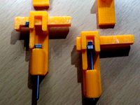
So going back to wiring our sensor. The signal wire with sensor activated goes to board ground and lo and behold the mirco switch black lead also goes to board ground, so if I just simply solder the diode now in series signal lead to the spade connector of the black lead we have just put a second Gucci inductive sensor switch in parallel with the micro switch that will turn on and off in the same way, towards Z stop min. Using Bill Nye ingenuity we are able to do what the micro switch has being doing all along but now does it with PFM hovering over board at an accurate distance with flair.
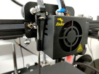
Now print the mount, mount the sensor and make your wires all nice and purdy with some handy soldering work and color coordinated shrink wrap. We'll move onto the next phase.
4 Auto level firmware adjustments in configuration.h settings
If you've made it this far it's time to take one arm; left or right, which it matters not, and reach around your back as far as you can and give yourself a good pat. As much as you may wish to believe someone is going to care about what you have accomplished thus far the reality is this small act of personal gratification... keep it clean ladies and gentlemen...is about the only reward you have for your efforts this far.
As stated earlier in Part 2 of this information I was able to obtain the 90% solution. To be more precise it was closer to the 99.99% solution as whomever was thoughtful enough to write Marlin (insert too numerous attributions here) built a solid foundation for auto level to operate. Very unlike my own mind, there's appeared appropriately structured and they dutifully tabbed out various functional areas within the program. This leaves us only to have to concern ourselves with minor modifications within configuration.h
From the obtained file written for the P802MA with auto leveling options set, I will cover the areas of potential concern where changes may be necessary. Again this will be found under the tab "configuration.h". I make apologies for the massive font but it appears to be some sort of issue with the hosting software.
Ladies and gentlemen I draw your attention to exhibit A:
// Travel limits after homing
define X_MAX_POS 220//relative distance from X Min Pos
define X_MIN_POS -8
define Y_MAX_POS 220//relative distance from Y Min Pos
define Y_MIN_POS 0
define Z_MAX_POS 215
define Z_MIN_POS 0
In this area you will be required to ensure that the print head finds itself at the left and forward most corner of the print bed. X min and Y min are determined by how far off that position resides from triggering their respective end stop switch. In my application the Y min position was at the point the Y end stop switch just closed thus Y Min Pos was 0. For X, the switch activated left of the print heads leftmost over bed position therefore I had to determine the distance and define the value which in this case was -8 mm.
Now the max position is quite simple as it is simply the dimension of the build are itself so for those of you challenged with arithmetic don't sweat adding or subtracting from the X and Y min positions you entered. The programmer did that dirty work for us and these relative positions are calculated from the end stop values we entered earlier.
Next up exhibit B:
ifdef AUTO_BED_LEVELING_GRID
// set the rectangle in which to probe
define LEFT_PROBE_BED_POSITION 30
define RIGHT_PROBE_BED_POSITION 160
define BACK_PROBE_BED_POSITION 175
define FRONT_PROBE_BED_POSITION 35
Suffice to say there is more than one pattern that can be used for checking the bed for level. In the interest of simplicity I will cover the one I used "GRID". Grid requires specifying the four outer corners of the pattern as offsets from the initial X and Y min positions entered in exhibit A. Now if one were somewhat reasonably proficient in math and able to visualize these points they would quickly arrive at the conclusion that these listed setting do not define not a perfect square.Elementary my dear Watson. I use archaic steel paper clips front and back to hold my build glass on and they don't play nice with the print head so the pattern avoids those areas. Less than ideal leveling but it works well none the less.
Lastly Exhibit C:
// these are the offsets to the probe relative to the extruder tip (Hotend - Probe)
define X_PROBE_OFFSET_FROM_EXTRUDER -55
define Y_PROBE_OFFSET_FROM_EXTRUDER -26
define Z_PROBE_OFFSET_FROM_EXTRUDER -0.40
This is the area that allows you to specify where your probe is in relation to the print head. Standing in front and looking top down anything with the probe mounted left of the head is a negative value. Probe mounted forwards toward you, again a negative value. Distance in mm. To the right or rearward, positive values but you knew that already....
Z Probe offest just define something for now or leave what's in there. We will go through calibrating and storing this values later as it requires so measurement and GCode entries to get them where they need to be.
That's the short version and if your running the same P802E as I am with your end stop switches roughly triggering in the same locations you won't even be required to modify these values for it to work. believe it's important to know where this information resides so that you at least have some basis of understanding of where to look if you have a different printer or things aren't working for you as advertised
5 Calibrating the sensor
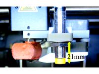
At this point you want to test the sensitivity of the sensor to detect the bed and mount it just above the height of the nozzle. If you're using glass on your build plate this won't be very much higher due to the sensitivity of the 8mm sensor when used with an aluminum build plate. The sensor must be higher than the nozzle so attempting to use a 4mm sensor isn't going to give you the sensitivity to get the required height if you've added a sheet of 3 mil glass above the aluminum. The 8mm sensor will just get you there. This manual calibration is a relatively crude setup using the LED as an indicator and the sheet of paper with the gap method for the nozzle in order to establish the nozzle to probe physical offset before calibrating. Remember the probe has to sit higher than the nozzle. Get the nozzle down on your sheet of paper with he normal drag clearance having the probe mounted slightly above ensuring it's still low enough that the LED is ON.
Now if you've retained the Z end stop micro switch as suggested earlier, you want to adjust that down to where the nozzle should never go which is when it comes in contact with the build plate. This switch set down here can act as a safety switch in the unlikely event the probe fails to detect the bed. This micro switch in normal operation should never be tripped as the extruder moves down to an initial layer position slightly above the bed but never touching the bed.
For the next part you are going to have to set up some way to send GCode to your printer. There are various methods to do this. I use the terminal area of Octoprint since I run Octoprint. There are other GCode senders. Here's one example that's free. https://chrome.google.com/webstore/detail/gcode-sender/ngncibnakmabjlfpadjagnbdjbhoelom?hl=en
Go through the process of setting up whatever your going to use and get connected to your printer using their instructions on how to use it.
Now through sending GCode and moving the Z axis up and down through the keypad interface we are going to establish what our Z Offset is and save that value to our printers EEPROM for it to be stored forever... or at least until we decide to store it again. We need to establish and save the fixed physical distance between the probe activation height and the height of the nozzle. This distance never changes unless you physically change the height of the probe in relation to the nozzle something we earlier established and tightened the probe in place with our paper and LED On trick.
Some suggest this is best done with the bed hot. I haven't found there to be much difference but I'll leave it up to you whether you want to heat your build plate first when doing the calibration.
Here's the series of steps. I will comment what objectives are with each one. For clarity comments are everything including and after "//" and are not sent to the printer. The printer may find it amusing but you probably won't appreciate the result.
G28 // Send the carriage to the center of the bed
M114 // Ok Mr. 3d printer, tell me what you believe is the current value of your Z axis position? If were lucky and it returns 0 for Z and we can skip the following 3 steps.
if we did not get a return of 0 for Z;
M851 Z-0 // I'm telling you Z is in fact 0.
M500 // Save this position to your memory as 0.
G28 // Re-center the carriage.
G92 Z10 // We need a little space for this next trick, move the extruder up 10mm for me please.
Using the printers keyboard interface we are going to move the head down in minute 0.1 increments until we have drag on a sheet of paper just as we'd set our extruder height up manually. When we like the amount of drag on the paper we go back to sending the subsequent GCode.
.
M114 // Tell me what you see the value of Z is now that I've moved the head down manually?
Ok now's the hard part because we have to do basic arithmetic using the returned value of Z.
If you look back we raised the nozzle 10mm from what we told the printer was 0. 0 isn't going to work for us because that's where the probe first trips and we need to go down to where the nozzle is snug on the paper. We got that height from our M114 and it's less than 10mm because we moved down from 10mm to get there. So how much did we move down? Well if the Z axis height was returned from our last M114 so for example if M114 returned 9.5mm then we moved down .5mm,, the difference between 10 and 9.5. So using this method our calculation is 10 minus the value returned by M114 for the Z axis height.
Now we are going use that value to tell the printer the offset and save it with the following:
M851 Z-(value) // "value" substitute with what you calculated. My example would have read "M851 Z-0.5". We're telling the printer that whatever it believed was the reference for Z before make that reference lower by the amount specified in our value hence the minus sign.
M500 // Store this forever and ever, even if the power is turned off... unless I change my mind down the road and tell you to do it again.
G28 // re-center the carriage.
Voila you should be done... but wait! there's an added bonus round.
If you want to check your paper clearance again just enter a G1 Z0 and the print head will descend the distance of offset to where your initial layer height has now been set.
Lastly the process can be repeated any number of times and if you physically move the probe up or down in the mount to make an adjustment you have to go through the entire process from the beginning to re-establish the corrected offset value.
6 Custom Start/End GCode
Let me start with reciting the Infinite Monkey Theorem; the theorem states that a monkey hitting keys at random on a typewriter keyboard for an infinite amount of time will almost surely type a given text, such as the complete works of William Shakespeare. Alright we're not the least bit concerned with iambic pentameter but suffice to say there are nearly endless arrangements of GCode that can be used and still have things work with a few exceptions. I will point out three items that I found of importance. You can copy paste the example or modify your existing code with a bed leveling addition. This is a working solution:
Start GCode
G21; metric values
G90; absolute distance mode
M140 S50; start bed warming to 50 degrees C.
M82; set extruder to absolute mode
M107; start with the fan off
G28; Home all axes
G28 X0 Y0; move X / Y to min endstops
G28 Z0; move Z to min endstops
G29; Run autolevel routine
G1 Z15.0 F {travel_speed}; move the nozzle up 15mm
G92 E0; zero the extruded length
G1 F200 E6; extrude 6mm of feed stock the amount retracted at end
G92 E0; zero the extruded length again
G1 F {travel_speed}; Putting message on LCD screen
M117 Printing ...
The first concern is placement of calibration and referencing code. The setting of G21 amd G90 before setting temperatures looks to be a requirement as calibrating and referencing that occurs with these entries I found has the additional action of defaulting other values and in the case of bed and nozzle temperature returning them to off therefore they should precede setting temperatures. You may note that this code starts the bed warming to 50 degrees C immediately afterward. The reason is the auto level sequence on a Tronxy is completed before the bed has reached 50 degrees therefore the time to re-calibrate for level isn't lost time as we're waiting on the bed to heat up anyway. This way we get the most up to date readings and there's no time penalty in doing so. I suppose you could introduce a delay if you want to take all your readings at 50 degrees C with the addition of an M190 S50 before bed leveling but I'm too impatient to wait and I haven't found any significant detrimental effect to the initial layer in not waiting.
The second thing is G29 has to be preceded by G28 for the printer to recheck it's min end stops.
Lastly retraction and extrusion settings. At the end of your last print the filament is retracted. This amount and speed may vary depending on whether or not you have a bowden extruder and the length of the tube to the extruder. The code here is for the supplied bowden on a P802E. You will see direction to extrude 6mm of filament in the start GCode. The reason it is 6mm in this case is because if we look at the end GCode there's a retraction of 6mm occurring so we at the very least want to bring the filament back to the nozzle when we're ready to print again. If you look at the end GCode it retracts 1mm (E-1), raises the nozzle and then retracts another 5mm (E-5).
End GCode
M104 S0 ;extruder heater off
M140 S0 ;heated bed heater off (if you have it)
G91 ;relative positioning
G1 E-1 F300 ;retract the filament a bit before lifting the nozzle, to release some of the pressure
G1 Z+0.5 E-5 X-20 Y-20 F9000 ;move Z up a bit and retract filament even more
G28 X0 Y0 ;move X/Y to min endstops, so the head is out of the way
G1 Y150 F5000 ;move completed part out
M84 ;steppers off
G90 ;absolute positioning
7 Things I inevitably forgot to think of...
I believe I've covered all the basics to get the P802E up and running and I have found that this setup works quite well for me. Virtually gone are the days of chucking out initial layer mishap resulting from nozzle height issues.
I would greatly appreciate feedback on any changes, additions or improvements you make to this setup.
A description on firmware set up and calibration is posted below the part description here.
Offsets are X-55, Y-26. This design allows for mounting the sensor in close proximity to the bed as aluminum used in the construction of the heated bed reduces the design range of the sensor considerably. With this design I am able to use the 8mm sensor with a glass build plate on the original supplied bed with minor allowances for it to clear the print. The design also conforms to physical requirements of the carriage assembly my Tronxy P802E came with. Additionally use of angles and curves allows it to be printed without the requirement for support material.
I am reasonably convinced any combination of sensor be it PNP, NPN, NO or NC can be wired into a controller by use of various settings, voltage dividers, mosfets and/or diodes to make them operable. For various reasons in my application I elected to use the following sensor:
LJ18A3-8-Z/BX 8mm Approach Sensor Inductive Proximity NPN NO Switch DC 6-36V LW
For my application the sensor is powered from the main 12VDC supply voltage to ensure operation within the sensor's design range. The sensor offers sufficient sensitivity to operate with an aluminum bed and will allow for the use of a glass build plate. On my Tronxy P802E, a 5VDC active-lo signal is supplied via the board's own Z end stop header pin to the Z end stop frame mounted micro switch and signal is sent through the NO micro switch to the Z end stop ground pin of a Melzi 2.0 "TRONXY" variant silk screened as board version 5. On measurement it appears this particular inductive sensor uses an internal pull up which in the untriggered state pulls the sensor line up to the supplied voltage. In this case the supplied 12VDC! To provide reverse current protection for this pull up state I installed a diode on the signal line thus the Z end stop input sees only it's own 5 volt active-lo signal which is pulled to ground when triggered. By using this arrangement the sensor behaves in the same manner as the supplied micro switch. Through wiring the sensor in parallel to the existing micro switch (diode protected sensor signal line to Z end stop switch input line) and setting the micro switch slightly lower than the sensor trigger point I was able to create a mechanical safety end stop should the inductive sensor fail. The micro switch is trigger at the point the extruder makes contact with the build plate thus mitigating possible serious damage from a unlikely sensor fault.
You will need to set up auto bed leveling in your firmware. I felt I was unable to satisfactorily configure the factory supplied Repetier firmware through the user interface to enable auto bed leveling to the degree I wish to tailor it. You may have reasonable success but I wanted control at the firmware level to optimize my settings thus requiring a complete revision to my printers firmware.
In my case my Melzi board required a more versatile Sanguino boot loader installation and in order to get things working the way I wanted, I configured a version of Marlin. Before embarking down the road of auto bed leveling I recommend investigating whether you are prepared to possibly go through the process of changing and modifying your firmware and potentially programming the bootloader with an ISP as the "out of the box" solution appears to be quite limiting. The benefits may outweigh the cost but for prints with long dimensions adhered to the build plate it is almost an indispensable requirement to ensure success.
Set up guide:
The following posts will go through the process in phases. Depending on what the TRONXY printer you received came with and what you wish to achieve these phases may or may not apply. Understand I have hands on experience only with P802E arriving with a Melzi 2.0 controller and Repetier firmware. Although much of the information will be adaptable to other applications, this is system I was directly working on.
The phases are as follows:
1 Uploading a bootloader (optional if your board will accept uploading firmware to it)
2 Installing new firmware
3 Installing the sensor
4 Auto level firmware adjustments in configuration.h settings
5 Calibrating the sensor
6 Custom Start/End GCode
7 Things I inevitably forgot to think of...
Before getting into the discussion it is important to note that as a result of developments in the Arduino IDE version compatibility issues pose many challenges. I will attempt to ensure that I mention what version of the IDE is being used when working with firmware. In some instances using the wrong version for which the firmware was written will fail to compile. Other instances may pose communication issues while others will pose challenges in terms of where to import libraries. Welcome to the open source (free software) world.
Lastly I offer this information as just that; information. I hold no responsibility or accountability for any damage you may do to yourself or your equipment by utilizing or applying this "information" in any way. The possibility exists to brick, burn or otherwise completely destroy your hardware as well as having your printer go absolutely haywire and self destruct into a pile of useless rubble. It may even elect to go terminator on your neighbors cat. PROCEED AT YOUR OWN RISK!
1 Uploading a bootloader (optionally required if your board will not accept uploading firmware to it)
Before even considering the boot loader you have to ask yourself whether you are able to achieve your auto level requirements using the existing firmware the printer was shipped with. If the answer is no then you have to see if your printer will accept uploaded code. My recommendation here is to obtain a copy of the original firmware your printer came with. At startup the printer display should give you an indication of what's installed. Although not absolutely necessary, having the original firmware will allow you to test the ability to program your controller and recover your printer back to factory settings should you wish to.
In my case my printer did not appear to have a boot loader that would communicate appropriately with any versions of Arduino IDE I attempted to connect to it. I investigated whether there were communication issues as a result of a clone FTDI USB to Serial adapter. Fortunately the Melzi board supplied with my printer had a legitimate FTDI chip. If you have a clone it is usable as well but you will have to investigate drivers and possible temporary bricking issues. WHQL drivers were released that can pose problems with communication and recoverable bricking issues with these CH340 clone chips. Google is your friend here but in my instance my board has the FTDI brand chip so uploading firmware came down to having a suitable boot loader.
The boot loader hardware file I use is Sanguino for ATmega1284p @ 16mhz. Visually looking at your board you should be able to identify this processor and the frequency on the oscillator. After installing Adruino IDE version 1.8.2. you will need to follow the instruction here to install Sanguino. http://dustsreprap.blogspot.ca/2015/06/better-way-to-install-sanguino-in.html. Now you will require an ISP. In my case I utilized an older Arduino Duemilanove. This is what I had and is not to say it's the best or only ISP around but I know this worked.
POINT OF NO RETURN! if you decide you need a boot loader installed understand that there are risks that you may not recover from. The boot loader is your controllers window to the outside world. Failure of the boot loader installation may brick your board. PROCEED AT YOUR OWN RISK! BE CERTAIN YOU WANT AND NEED THIS AND ARE WILLING TO ACCEPT THE OUTCOME GOOD OR BAD.
Steps I went through as follows:
-Wired my Arduino as ISP to the "old wiring" scheme from the Example sketch that comes with 1.8.2 and removed the comment for this to work (not sure this is a factor but that's the way I had it wired to work with the older IDE for my tests).
-Removed all wired connections from the Melzi less end stop switch inputs. Critical!
-Uploaded the Arduino as ISP sketch to the duemilanove. (probably work with UNO etc.)
-Melzi reset jumper installed. USB power jumper moved to USB position. Connect ISP connector as per instructions in sketch between boards.
-Set board to Sanguino. Processor Atmega1284p 16mhz.
-Set Port to comm port of duemilanove.
-USB cable to duemilianove. No USB cable to Melzi.
-Burn bootloader.
It is important to note that any power to the Arduino and Melzi during this process came solely from the one USB connection to the Arduino. No other power was applied. Power went through the Adruino to the Melzi with the Melzi obtaining power through the 6 pin ISP connector from the Arduino with the USB jumper setting set on the Melzi.
2 Installing new firmware
Assuming you've already covered off requirements of Phase 1 and now have a Melzi in your Tronxy with a boot loader that will allow you to upload code through it's USB port it's time to get onto the code. Firmware comes in various flavors and Tronxy appears to have written firmware for their printers based on both Repetier and Marlin. The printer I received was supplied with Repetier and had Tronxy's version 1.6 of it. After playing around with Repetier online configuration tool I quickly came to the understanding A. I have no idea what I needed to do with end stop switch settings to get this working or B. Repetier is dead set on using max end stops for bed leveling; something the Melzi isn't conducive to do and I'm unwilling to re-invent the wheel (wheel being Tronxy P802E in this case) to make this work with max end stops. Anyway despite putting in a semi-serious effort with Repetier I abandoned that avenue and decided on Marlin. I managed to locate a auto level version written for the P802MA. Unfortunately it wasn't plug and play so I went about calibrating various bed adjustments, probe offsets and pattern settings to get what I wanted from it. It is the older V1.0 but works well and was the 90% solution so I'm not rushing to reconfigure to 1.1 just yet.
The version compiles in Arduino 1.6.9 but has issue compiling with 1.8.2 the latest version as of this writing. Rather than fixing the code I elected to try the older 1.6.9 IDE and it worked. This requires downloading the older IDE and once again adding in Sanguino support to this IDE to allow it to communicate to your Melzi with the Sanguino boot loader. Settings for communication now become those for your Melzi's port. Hardware settings remain Sanguino w/ATmega1284p @ 16mhz now set in the older IDE.
Melzi jumper settings now back to default powered by input 12V. Make shift Arduino Duemilanove ISP disconnected and sent back into retirement. Reset jumper remains installed on Melzi.
Verify-Compile-Upload.
The system should now reboot to the new firmware which can be verified by the IDE upload confirmation message and the printer display message.on startup.
3 Installing the sensor
The sensor I chose was a LJ18A3-8-Z/BX 8mm Approach Sensor Inductive Proximity NPN NO Switch DC 6-36V LW. There is conflicting information out there regarding the reliability of operation of these sensors at 5 volts which is below the minimum specified operating voltage. It appears the main reasons for people wanting to operate the sensor at 5 volts is to limit the voltage to that used in the logic level of the Melzi board thereby mitigating potential damage to the board as a result of feeding it a higher voltage. Two potential issues arise from this approach. First off it's below the sensors minimum specified design voltage and secondarily it is now putting addition load on the 5VDC supply of the Melzi to power the sensor. By utilizing the 12VDC power supply voltage both of those concerns are removed. The downside is now the sensor has 12VDC going to it and we want to make sure that isn't what's coming out.
So let's look at the behavior of the sensor. The sensor gets fed positive 12VDC on the Brown wire and negative 12VDC on the Blue wire. If we bring something metallic near the sensor it triggers and the LED illuminates. You can play with all this on the side using a 9V battery just substitute 9V for 12V in your readings. Now we have the Black signal wire we want to use to act as an input somehow to the Melzi. If we hook the positive of a voltmeter to the Black signal wire and the negative to the same Blue ground wire negative 12VDC is on; the signal wire un-tripped reveals 12VDC and virtually zero volts when tripped and the LED is lit. Switching now to ohms we see some resistance on the line when un-tripped and virtually zero resistance when tripped. Basically from this we derive that this sensor wire can be a switch to ground when tripped but with the appearance of 12VDC when un-tripped there is a condition there we don't have any use for and is detrimental to the well being of our board. Some people have suggested this voltage is the signal wire "floating" and not to be concerned with the voltage. That's all well and good but I don't want to take a chance that it's being pulled up to 12VDC so I go a step further to eliminate it altogether. We only want to allow current to flow to ground when tripped but the other part of it's operation we don't want, the 12VDC flowing out to our board so we can use a diode to allow current to flow only to ground and block the 12VDC from going out the other way. To ensure the diode is in the correct anode to cathode current flow orientation we connect it to the end of the black lead and run our tests again. If we have it right 12VDC is NEVER seen on the signal wire and the signal connects to ground when tripped. We now have created a switch to ground with no other ill side effects.
If we look at our Z end stop micro switch it has two wires. One wire, yellow on my printer, reads 5VDC when checked for voltage. The other black wire to the switch reads zero ohms when comparing readings to our boards ground. So we can deduce that either the logic of the Z end stop is held high and closing the NO switch of the micro switch takes that 5V down to ground (active-low) or we may also speculate the black wire is brought high from 5 volts provided by the yellow wire (active-high). Since the black shares ground with board this second deduction must be false as no circuit would simply feed 5V directly to board ground when the switch is closed. Active-low it would appear to be.
So going back to wiring our sensor. The signal wire with sensor activated goes to board ground and lo and behold the mirco switch black lead also goes to board ground, so if I just simply solder the diode now in series signal lead to the spade connector of the black lead we have just put a second Gucci inductive sensor switch in parallel with the micro switch that will turn on and off in the same way, towards Z stop min. Using Bill Nye ingenuity we are able to do what the micro switch has being doing all along but now does it with PFM hovering over board at an accurate distance with flair.
Now print the mount, mount the sensor and make your wires all nice and purdy with some handy soldering work and color coordinated shrink wrap. We'll move onto the next phase.
4 Auto level firmware adjustments in configuration.h settings
If you've made it this far it's time to take one arm; left or right, which it matters not, and reach around your back as far as you can and give yourself a good pat. As much as you may wish to believe someone is going to care about what you have accomplished thus far the reality is this small act of personal gratification... keep it clean ladies and gentlemen...is about the only reward you have for your efforts this far.
As stated earlier in Part 2 of this information I was able to obtain the 90% solution. To be more precise it was closer to the 99.99% solution as whomever was thoughtful enough to write Marlin (insert too numerous attributions here) built a solid foundation for auto level to operate. Very unlike my own mind, there's appeared appropriately structured and they dutifully tabbed out various functional areas within the program. This leaves us only to have to concern ourselves with minor modifications within configuration.h
From the obtained file written for the P802MA with auto leveling options set, I will cover the areas of potential concern where changes may be necessary. Again this will be found under the tab "configuration.h". I make apologies for the massive font but it appears to be some sort of issue with the hosting software.
Ladies and gentlemen I draw your attention to exhibit A:
// Travel limits after homing
define X_MAX_POS 220//relative distance from X Min Pos
define X_MIN_POS -8
define Y_MAX_POS 220//relative distance from Y Min Pos
define Y_MIN_POS 0
define Z_MAX_POS 215
define Z_MIN_POS 0
In this area you will be required to ensure that the print head finds itself at the left and forward most corner of the print bed. X min and Y min are determined by how far off that position resides from triggering their respective end stop switch. In my application the Y min position was at the point the Y end stop switch just closed thus Y Min Pos was 0. For X, the switch activated left of the print heads leftmost over bed position therefore I had to determine the distance and define the value which in this case was -8 mm.
Now the max position is quite simple as it is simply the dimension of the build are itself so for those of you challenged with arithmetic don't sweat adding or subtracting from the X and Y min positions you entered. The programmer did that dirty work for us and these relative positions are calculated from the end stop values we entered earlier.
Next up exhibit B:
ifdef AUTO_BED_LEVELING_GRID
// set the rectangle in which to probe
define LEFT_PROBE_BED_POSITION 30
define RIGHT_PROBE_BED_POSITION 160
define BACK_PROBE_BED_POSITION 175
define FRONT_PROBE_BED_POSITION 35
Suffice to say there is more than one pattern that can be used for checking the bed for level. In the interest of simplicity I will cover the one I used "GRID". Grid requires specifying the four outer corners of the pattern as offsets from the initial X and Y min positions entered in exhibit A. Now if one were somewhat reasonably proficient in math and able to visualize these points they would quickly arrive at the conclusion that these listed setting do not define not a perfect square.Elementary my dear Watson. I use archaic steel paper clips front and back to hold my build glass on and they don't play nice with the print head so the pattern avoids those areas. Less than ideal leveling but it works well none the less.
Lastly Exhibit C:
// these are the offsets to the probe relative to the extruder tip (Hotend - Probe)
define X_PROBE_OFFSET_FROM_EXTRUDER -55
define Y_PROBE_OFFSET_FROM_EXTRUDER -26
define Z_PROBE_OFFSET_FROM_EXTRUDER -0.40
This is the area that allows you to specify where your probe is in relation to the print head. Standing in front and looking top down anything with the probe mounted left of the head is a negative value. Probe mounted forwards toward you, again a negative value. Distance in mm. To the right or rearward, positive values but you knew that already....
Z Probe offest just define something for now or leave what's in there. We will go through calibrating and storing this values later as it requires so measurement and GCode entries to get them where they need to be.
That's the short version and if your running the same P802E as I am with your end stop switches roughly triggering in the same locations you won't even be required to modify these values for it to work. believe it's important to know where this information resides so that you at least have some basis of understanding of where to look if you have a different printer or things aren't working for you as advertised
5 Calibrating the sensor
At this point you want to test the sensitivity of the sensor to detect the bed and mount it just above the height of the nozzle. If you're using glass on your build plate this won't be very much higher due to the sensitivity of the 8mm sensor when used with an aluminum build plate. The sensor must be higher than the nozzle so attempting to use a 4mm sensor isn't going to give you the sensitivity to get the required height if you've added a sheet of 3 mil glass above the aluminum. The 8mm sensor will just get you there. This manual calibration is a relatively crude setup using the LED as an indicator and the sheet of paper with the gap method for the nozzle in order to establish the nozzle to probe physical offset before calibrating. Remember the probe has to sit higher than the nozzle. Get the nozzle down on your sheet of paper with he normal drag clearance having the probe mounted slightly above ensuring it's still low enough that the LED is ON.
Now if you've retained the Z end stop micro switch as suggested earlier, you want to adjust that down to where the nozzle should never go which is when it comes in contact with the build plate. This switch set down here can act as a safety switch in the unlikely event the probe fails to detect the bed. This micro switch in normal operation should never be tripped as the extruder moves down to an initial layer position slightly above the bed but never touching the bed.
For the next part you are going to have to set up some way to send GCode to your printer. There are various methods to do this. I use the terminal area of Octoprint since I run Octoprint. There are other GCode senders. Here's one example that's free. https://chrome.google.com/webstore/detail/gcode-sender/ngncibnakmabjlfpadjagnbdjbhoelom?hl=en
Go through the process of setting up whatever your going to use and get connected to your printer using their instructions on how to use it.
Now through sending GCode and moving the Z axis up and down through the keypad interface we are going to establish what our Z Offset is and save that value to our printers EEPROM for it to be stored forever... or at least until we decide to store it again. We need to establish and save the fixed physical distance between the probe activation height and the height of the nozzle. This distance never changes unless you physically change the height of the probe in relation to the nozzle something we earlier established and tightened the probe in place with our paper and LED On trick.
Some suggest this is best done with the bed hot. I haven't found there to be much difference but I'll leave it up to you whether you want to heat your build plate first when doing the calibration.
Here's the series of steps. I will comment what objectives are with each one. For clarity comments are everything including and after "//" and are not sent to the printer. The printer may find it amusing but you probably won't appreciate the result.
G28 // Send the carriage to the center of the bed
M114 // Ok Mr. 3d printer, tell me what you believe is the current value of your Z axis position? If were lucky and it returns 0 for Z and we can skip the following 3 steps.
if we did not get a return of 0 for Z;
M851 Z-0 // I'm telling you Z is in fact 0.
M500 // Save this position to your memory as 0.
G28 // Re-center the carriage.
G92 Z10 // We need a little space for this next trick, move the extruder up 10mm for me please.
Using the printers keyboard interface we are going to move the head down in minute 0.1 increments until we have drag on a sheet of paper just as we'd set our extruder height up manually. When we like the amount of drag on the paper we go back to sending the subsequent GCode.
.
M114 // Tell me what you see the value of Z is now that I've moved the head down manually?
Ok now's the hard part because we have to do basic arithmetic using the returned value of Z.
If you look back we raised the nozzle 10mm from what we told the printer was 0. 0 isn't going to work for us because that's where the probe first trips and we need to go down to where the nozzle is snug on the paper. We got that height from our M114 and it's less than 10mm because we moved down from 10mm to get there. So how much did we move down? Well if the Z axis height was returned from our last M114 so for example if M114 returned 9.5mm then we moved down .5mm,, the difference between 10 and 9.5. So using this method our calculation is 10 minus the value returned by M114 for the Z axis height.
Now we are going use that value to tell the printer the offset and save it with the following:
M851 Z-(value) // "value" substitute with what you calculated. My example would have read "M851 Z-0.5". We're telling the printer that whatever it believed was the reference for Z before make that reference lower by the amount specified in our value hence the minus sign.
M500 // Store this forever and ever, even if the power is turned off... unless I change my mind down the road and tell you to do it again.
G28 // re-center the carriage.
Voila you should be done... but wait! there's an added bonus round.
If you want to check your paper clearance again just enter a G1 Z0 and the print head will descend the distance of offset to where your initial layer height has now been set.
Lastly the process can be repeated any number of times and if you physically move the probe up or down in the mount to make an adjustment you have to go through the entire process from the beginning to re-establish the corrected offset value.
6 Custom Start/End GCode
Let me start with reciting the Infinite Monkey Theorem; the theorem states that a monkey hitting keys at random on a typewriter keyboard for an infinite amount of time will almost surely type a given text, such as the complete works of William Shakespeare. Alright we're not the least bit concerned with iambic pentameter but suffice to say there are nearly endless arrangements of GCode that can be used and still have things work with a few exceptions. I will point out three items that I found of importance. You can copy paste the example or modify your existing code with a bed leveling addition. This is a working solution:
Start GCode
G21; metric values
G90; absolute distance mode
M140 S50; start bed warming to 50 degrees C.
M82; set extruder to absolute mode
M107; start with the fan off
G28; Home all axes
G28 X0 Y0; move X / Y to min endstops
G28 Z0; move Z to min endstops
G29; Run autolevel routine
G1 Z15.0 F {travel_speed}; move the nozzle up 15mm
G92 E0; zero the extruded length
G1 F200 E6; extrude 6mm of feed stock the amount retracted at end
G92 E0; zero the extruded length again
G1 F {travel_speed}; Putting message on LCD screen
M117 Printing ...
The first concern is placement of calibration and referencing code. The setting of G21 amd G90 before setting temperatures looks to be a requirement as calibrating and referencing that occurs with these entries I found has the additional action of defaulting other values and in the case of bed and nozzle temperature returning them to off therefore they should precede setting temperatures. You may note that this code starts the bed warming to 50 degrees C immediately afterward. The reason is the auto level sequence on a Tronxy is completed before the bed has reached 50 degrees therefore the time to re-calibrate for level isn't lost time as we're waiting on the bed to heat up anyway. This way we get the most up to date readings and there's no time penalty in doing so. I suppose you could introduce a delay if you want to take all your readings at 50 degrees C with the addition of an M190 S50 before bed leveling but I'm too impatient to wait and I haven't found any significant detrimental effect to the initial layer in not waiting.
The second thing is G29 has to be preceded by G28 for the printer to recheck it's min end stops.
Lastly retraction and extrusion settings. At the end of your last print the filament is retracted. This amount and speed may vary depending on whether or not you have a bowden extruder and the length of the tube to the extruder. The code here is for the supplied bowden on a P802E. You will see direction to extrude 6mm of filament in the start GCode. The reason it is 6mm in this case is because if we look at the end GCode there's a retraction of 6mm occurring so we at the very least want to bring the filament back to the nozzle when we're ready to print again. If you look at the end GCode it retracts 1mm (E-1), raises the nozzle and then retracts another 5mm (E-5).
End GCode
M104 S0 ;extruder heater off
M140 S0 ;heated bed heater off (if you have it)
G91 ;relative positioning
G1 E-1 F300 ;retract the filament a bit before lifting the nozzle, to release some of the pressure
G1 Z+0.5 E-5 X-20 Y-20 F9000 ;move Z up a bit and retract filament even more
G28 X0 Y0 ;move X/Y to min endstops, so the head is out of the way
G1 Y150 F5000 ;move completed part out
M84 ;steppers off
G90 ;absolute positioning
7 Things I inevitably forgot to think of...
I believe I've covered all the basics to get the P802E up and running and I have found that this setup works quite well for me. Virtually gone are the days of chucking out initial layer mishap resulting from nozzle height issues.
I would greatly appreciate feedback on any changes, additions or improvements you make to this setup.
Similar models
thingiverse
free
Tronxy P802e Inductive/Capacitive Sensor Mount by srbaude86
... least half of whats written here before i installed my probe - would have saved my me 2 days of yelling at my printer. good luck
thingiverse
free
Alunar m508 Z Sensor Front Fan Holder by jacobf18
...cause the sensor should the sensing distance that goes below the extruder nozzle. use 7-zip file manager to extract my firmware.
thingiverse
free
Ender 5 Allen Key Bed Leveling Bracket
... manually triggering it and make sure the offsets are correct and your allen doesn't crash into anything!
happy printing!! ;)
thingiverse
free
Anet A8 & Prusa i3 Extuder Carriage with Front Mount 18mm, 12mm, 8mm Sensor or No Sensor and Options! by morganlowe
....
updates:
2/11/18 changed fillet on fan mount to make it easier to print.
please like, comment and share! thank you and enjoy!
thingiverse
free
CrashProbe (Z auto leveling by Crash) by Dexerit
...8 x0 y0 ;home x and y only
g29 ;3 point bed probe
g1 z.5 f200 ;force probe retraction
source: http://reprap.org/wiki/crashprobe
thingiverse
free
Wanhao D6 Induction Probe Mount by 1bigpig
...be_calibration_updated.pdf. it also included the required g-code that needs to be added to your existing slicer starting script.
thingiverse
free
Z End Point switch replacement for Auto Level probe by marungao
... motor. well, now there is: just put some metal beneath the z probe using this "thing".
i'm using repetier firmware
thingiverse
free
How to attach a LJC18A3-H-Z/BX capacitive probe via optocoupler to Creality Ender 3 (and other printers) by Arminth
...prove it over time.
cheers
armin
ps: i had to add a file from https://www.thingiverse.com/thing:13053 to make this thing visible.
thingiverse
free
Anycubic Mega Zero Allen Key Probe by qystan
... babystepping
define babystep_zprobe_offset
add this line to your slicer to load the leveling mesh before start of print.
m420 s1
grabcad
free

Tevo Tarantula Auto Bed Levelling with E3DV6 Hotend
...nter was built off arcaded's walkthrough, so if you followed that you should be good!!
drop us a $$ if you like it!!
enjoy!
Superflex
thingiverse
free

iPhone 6s Case
...iphone 6s case thingiverse superflexble iphone 8 plus case (made with...
thingiverse
free

iPhone 8 Plus Case
...iphone 8 plus case thingiverse superflexble iphone 8 plus case (made with...
thingiverse
free
Illuminated Iron Man Arc Reactor
...strand a. micro center is where i got mine: https://www.microcenter.com/product/471982/solarbotics-superflex3m-90-led-strand-with-3xaa-battery-box---blue double sided tape, to attach the detail pieces to...
thingiverse
free

Circuit Board Post 3mm by Superflex_Plastic_Fantastic
... linked one of my designs here for a mosfet mount showing it in a practical application:https://www.thingiverse.com/thing:2369923
grabcad
free

Kaleidoscope
...135-140 mm. build with or without light box. led: superflex led flat 120º 3,1v white. battery cr2932 (3v). nice...
Inductive
turbosquid
$2
Induction hob
...quid
royalty free 3d model induction hob for download as skp on turbosquid: 3d models for games, architecture, videos. (1564919)
turbosquid
$10
Induction Hob
... 3d model whirlpool induction hob for download as max and obj on turbosquid: 3d models for games, architecture, videos. (1390871)
3ddd
$1

Siemens Induction Cooktop
...duction cooktop
3ddd
варочная поверхность , siemens
induction cooktop siemens eh975md21p
turbosquid
$10
Induction cooker
...del induction cooker for download as sldpr, max, fbx, and obj on turbosquid: 3d models for games, architecture, videos. (1698439)
3d_export
$15

Induction Furnace Model 3D Model
...l
3dexport
inductor induction furnace ironworks cast steel stove hearth
induction furnace model 3d model conqueror 38004 3dexport
turbosquid
$25

Britannia Delphi Induction Oven
... available on turbo squid, the world's leading provider of digital 3d models for visualization, films, television, and games.
turbosquid
$50

Induction 4-Burner Cooktop Gaggenau
...3d model induction 4-burner cooktop gaggenau for download as on turbosquid: 3d models for games, architecture, videos. (1256929)
turbosquid
$25
48W_Tuscany Range - Burners-Griddle-Induction
... available on turbo squid, the world's leading provider of digital 3d models for visualization, films, television, and games.
turbosquid
$15
Miele KM 6115 Induction Cooker
... available on turbo squid, the world's leading provider of digital 3d models for visualization, films, television, and games.
3d_export
$19
Electric motor electrical induction engine machine industrial rotation
...tion engine machine industrial rotation asynchronous electromotor electricity editable generator coil 2.files include max fbx obj
Fantastic
3d_export
$10

fantastic island
...fantastic island
3dexport
a fantastic island in the style of low poly . it will fit perfectly into the game.
3d_ocean
$29

Fantastic robot
...ipede fantasy fi insect materials robot robotic sci textures
fantastic robot 3d models. very detailed mechanical fantastic robot.
3d_export
$15

fantastic plane
...fantastic plane
3dexport
turbosquid
$47

Fantastic ring
...uid
royalty free 3d model fantastic ring for download as 3dm on turbosquid: 3d models for games, architecture, videos. (1228810)
turbosquid
$39

Fantastical diorama
...royalty free 3d model fantastical diorama for download as fbx on turbosquid: 3d models for games, architecture, videos. (1493713)
turbosquid
$5

Fantastic Sword
...id
royalty free 3d model fantastic sword for download as obj on turbosquid: 3d models for games, architecture, videos. (1567620)
turbosquid
$13

Fantastic cat
...lty free 3d model fantastic cat for download as fbx and blend on turbosquid: 3d models for games, architecture, videos. (1220492)
turbosquid
$5

Fantastic house
...lty free 3d model fantastic house for download as max and fbx on turbosquid: 3d models for games, architecture, videos. (1454375)
3d_export
free

fantastic park
...fantastic park
3dexport
3d_export
free

fantastic boat
...fantastic boat
3dexport
my canal :
8Mm
turbosquid
$50

8MM CAMERA.max
... available on turbo squid, the world's leading provider of digital 3d models for visualization, films, television, and games.
turbosquid
$19
kodak 8mm
... available on turbo squid, the world's leading provider of digital 3d models for visualization, films, television, and games.
turbosquid
$1

Brass Bush Bearing 8mm ID
... available on turbo squid, the world's leading provider of digital 3d models for visualization, films, television, and games.
turbosquid
$20

wrench big collection from 8mm to 32mm
...llection from 8mm to 32mm for download as obj, fbx, and sldas on turbosquid: 3d models for games, architecture, videos. (1438111)
turbosquid
$1

Flexible Shaft Coupling 6mm x 8mm
... available on turbo squid, the world's leading provider of digital 3d models for visualization, films, television, and games.
turbosquid
$1

Flexible shaft coupling 5mm x 8mm
... available on turbo squid, the world's leading provider of digital 3d models for visualization, films, television, and games.
turbosquid
$15

German WWII Breda MG-8mm Ammo Box (Low Poly)
...g-8mm ammo box (low poly) for download as obj, fbx, and blend on turbosquid: 3d models for games, architecture, videos. (1395526)
3ddd
free

Treasures of the Sea
...treasures of the sea 3ddd бижутерия d=8mm ...
3d_export
$5
double thread screw
...thread length: 10 mm total length: 41 mm diameter: 8mm ...
3d_export
$5
large double thread screw
...thread length: 10 mm total length: 115 mm diameter: 8mm ...
Sensor
3d_export
free

parking sensor
...parking sensor
3dexport
car parking sensor
turbosquid
$1
Sensor
... available on turbo squid, the world's leading provider of digital 3d models for visualization, films, television, and games.
3d_export
$5
Smoke sensor
...port
smoke sensor, can be an impressive element for your projects. easy to use, realistic image, low polygon, quality materials.
3d_export
$5
Air Quality Sensor v1
...air quality sensor v1
3dexport
air quality sensor v1
3d_export
$15
float sensor
...e up render. - all parts and materials are logically named. other formats ================= - collada (.dae) - autodesk fbx - obj
turbosquid
$26
Wind sensor C
...free 3d model wind sensor c for download as 3ds, obj, and fbx on turbosquid: 3d models for games, architecture, videos. (1328943)
turbosquid
$26
Wind sensor B
...free 3d model wind sensor b for download as 3ds, obj, and fbx on turbosquid: 3d models for games, architecture, videos. (1328168)
3d_export
$5
ultrasound sensor
...ivers convert ultrasound into electrical signals, and transceivers can both transmit and receive ultrasound. export in: -obj -fbx
3ddd
free
Вытяжка Shindo pallada sensor
... вытяжка
вытяжка shindo pallada sensor. в двух размерах - 600 и 900. текстуры в комплекте.
turbosquid
$52
Wind sensor A B C
...
royalty free 3d model wind sensor a b c for download as fbx on turbosquid: 3d models for games, architecture, videos. (1408406)
Plastic
archibase_planet
free

Plastic
...plastic
archibase planet
moulding friezes moldings border pilaster
deco plastic dw - 3d model for interior 3d visualization.
turbosquid
$1

Plastics
...
royalty free 3d model plastics for download as blend and fbx on turbosquid: 3d models for games, architecture, videos. (1581776)
archibase_planet
free

Plastic
...lastic
archibase planet
moulding friezes moldings border pilaster decor
deco plastic rz - 3d model for interior 3d visualization.
3ddd
$1
Plastic Playground
... kids , toy , child
plastic playground
3d_export
$5
plastic lid
...plastic lid
3dexport
plastic lid
3d_export
$5
plastic clothespin
...plastic clothespin
3dexport
plastic clothespin
3d_ocean
$3
Plastic Packaging
...ging plastic
intended for blender, cycles: plastic packaging to place your product in. subdivision modifier has not been applied.
3ddd
$1
plastic box
... ящик
model of plastic box for fruits in 3 levels of detail. highpoly - 23,6k, midpoly - 7,3k and lowpoly - 2,6k polygons.
3d_ocean
$12

Plastic Chair
...furniture plastic chair side chair
3d model of plastic chair. 3ds and obj multi format files included. scanline renderer version.
3d_ocean
$1

Glossy Plastic
...glossy plastic
3docean
3dsmax glossy meterials glow plastic vray
easy usable meterials
Mount
3d_export
free

mounting bracket
...mounting plate is the portion of a hinge that attaches to the wood. mounting plates can be used indoors, cabinetry and furniture.
turbosquid
$2

MOUNTING
... available on turbo squid, the world's leading provider of digital 3d models for visualization, films, television, and games.
turbosquid
free

Mounts
... available on turbo squid, the world's leading provider of digital 3d models for visualization, films, television, and games.
turbosquid
free

Mount Fuji
...fuji
turbosquid
free 3d model mount fuji for download as obj on turbosquid: 3d models for games, architecture, videos. (1579977)
3d_export
$5

Headphone mount LR
...headphone mount lr
3dexport
headphone mount l+r
turbosquid
$39

Mount rainier
...quid
royalty free 3d model mount rainier for download as fbx on turbosquid: 3d models for games, architecture, videos. (1492586)
turbosquid
$5

pipe mounting
...quid
royalty free 3d model pipe mounting for download as obj on turbosquid: 3d models for games, architecture, videos. (1293744)
turbosquid
$3

Mounting Tires
...uid
royalty free 3d model mounting tires for download as fbx on turbosquid: 3d models for games, architecture, videos. (1708511)
3d_export
$5

Magnetic GoPro Mount
...pro mount
3dexport
cool magnetic mount for gopro. allows you to mount the camera on flat metal surfaces and get exclusive shots.
turbosquid
$5

Stone Mount
...ty free 3d model stone mount for download as ma, obj, and fbx on turbosquid: 3d models for games, architecture, videos. (1370306)